Texas Instruments DS90UB954-Q1EVM User Manual
Hide thumbs
Also See for DS90UB954-Q1EVM:
- User manual (67 pages) ,
- User manual (64 pages) ,
- User manual (66 pages)
Table of Contents
Advertisement
Quick Links
The Texas Instruments DS90UB954-Q1EVM evaluation module (EVM) is a functional board design for
evaluating the DS90UB954-Q1 FPD-Link III deserializer, which converts serialized camera data to MIPI
CSI-2 for processing. The MIPI CSI-2 output has four available lanes, and can be configured for either
four-lane output or replicated two-lane output. When paired with a DS90UB953-Q1 serializer, the
DS90UB954-Q1 receives data from imagers supporting up to 2MP/60fps and 4MP/30fps cameras as well
as satellite RADAR. The DS90UB954-Q1 also supports up to 1MP/60fps and 2MP/30fps imagers when
coupled with DS90UB913A/933 serializers.
The DS90UB954-Q1EVM is configured for communication with a DS90UB953-Q1 on channel 0 (RX0),
and a DS90UB933-Q1 on channel 1 (RX1). The EVM has two Rosenberger FAKRA connectors and
configurable power-over-coax (POC) voltage for connecting the camera modules (not included). FPD-Link
III interfaces also includes a separate low latency bi-directional control channel that conveys control
information from an I
synchronization and functional safety features also make use of this bi-directional control channel to
program registers in the DS90UB954-Q1 as well as the connected serializer and any remote I2C
connected devices. There is an onboard MSP430 which functions as a USB2ANY bridge for interfacing
with a PC for evaluation. The USB2ANY interfaces with the Analog LaunchPAD GUI tool.
...................................................................................................................
1
2
3
4
5
6
7
8
9
10
11
12
13
14
15
1
2
3
4
5
6
7
8
9
10
SNLU223 - August 2017
Submit Documentation Feedback
DS90UB954-Q1EVM Quick Start
2
C port. General purpose I/O signals such as those required for camera
............................................................................................................
..........................................................................................................
................................................................................
........................................................................................................
.........................................................................................................
....................................................................................................
..........................................................................................................
.....................................................................................
...........................................................................................
.....................................................................................
...................................................................................
List of Figures
........................................................................................................
........................................................................................................
......................................................................................................
........................................................................................
...........................................................................................
..........................................................................................................
Copyright © 2017, Texas Instruments Incorporated
Contents
.........................................
.........................................................................
.................................................................
.................................................................
..................................................................
DS90UB954-Q1EVM Quick Start
User's Guide
SNLU223 - August 2017
3
3
5
11
12
12
12
13
13
....................
14
19
23
......
26
34
44
3
4
4
5
6
7
12
15
15
16
1
Advertisement
Table of Contents

Subscribe to Our Youtube Channel
Related Manuals for Texas Instruments DS90UB954-Q1EVM


Summary of Contents for Texas Instruments DS90UB954-Q1EVM
-
Page 1: Table Of Contents
SNLU223 – August 2017 DS90UB954-Q1EVM Quick Start The Texas Instruments DS90UB954-Q1EVM evaluation module (EVM) is a functional board design for evaluating the DS90UB954-Q1 FPD-Link III deserializer, which converts serialized camera data to MIPI CSI-2 for processing. The MIPI CSI-2 output has four available lanes, and can be configured for either four-lane output or replicated two-lane output. - Page 2 DS90UB954-Q1EVM Maine Circuit - Page 1 ..............DS90UB954-Q1EVM CSI-2 Connectors - Page 2 ................DS90UB954-Q1EVM PoC Circuits - Page 3 ............DS90UB954-Q1EVM Power Distribution Circuits - Page 4 ................DS90UB954-Q1EVM LED Circuits - Page 5 ..............DS90UB954-Q1EVM USB2ANY Circuits - Page 6 ................
-
Page 3: Introduction
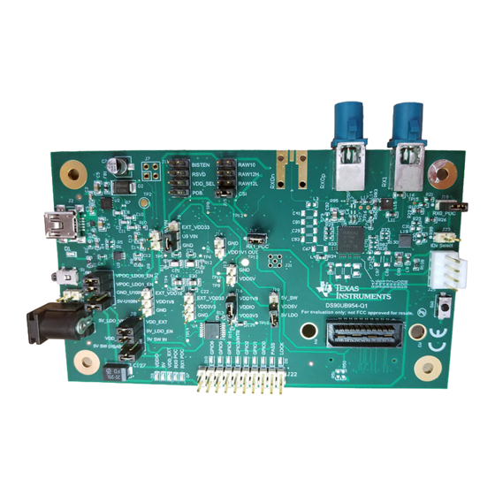
Figure 1. DS90UB954-Q1EVM Quick Start Guide System Requirements 2.1.1 Included Components The major components of the DS90UB954-Q1EVM are: • DS90UB954-Q1 • On-board Power-over-Coax (POC) interface • Two FAKRA coax connectors for digital video, power, control and diagnostics •... -
Page 4: Applications Diagram
MIPI CSI-2 1.6 Gbps/lane X 4 DS90UB933 RAW 10/12 Serializer Figure 2. Applications Diagram Major Components of DS90UB954-Q1EVM Figure 3. Interfacing to the EVM DS90UB954-Q1EVM Quick Start SNLU223 – August 2017 Submit Documentation Feedback Copyright © 2017, Texas Instruments Incorporated... -
Page 5: Ds90Ub954-Q1Evm Board Configuration -Evaluation Board Connections
3. Configure Power Over Coax power supplies for RX0 and RX1 with J18 and J17 respectively. 4. Connect the DS90UB954-Q1EVM to DS90UB953-Q1EVM to RX0 and/or DS90UB933-Q1EVM to RX1 using coax cable 5. Interface MIPI CSI-2 output signals (J24) to test equipment or host processor (optional, not required to check status of FPD-Link III connection between serializer and deserializer) 6. -
Page 6: Power Over Coax Network For Use With Ds90Ub953
Power Over Coax Interface The DS90UB954-Q1EVM offers two power over coax interfaces (POC) to connect cameras through a coaxial cable with FAKRA connectors. Power is delivered on the same conductor that is used to transmit video and control channel data between the host and the camera. By default, 5V power supply is applied over the coax cable. -
Page 7: Power Over Coax Network For Use With Ds90Ub933
POC. DS90UB913A-Q1EVM with DS90UB954-Q1EVM, open J17 or J18 to disable POC, and either power the DS90UB913A-Q1EVM separately or by applying 5V to the J17 or J18 pin on DS90UB954-Q1EVM. Table 2. Power Over Coax Power Supply Feed Configuration Reference... -
Page 8: Mipi Csi-2 Output Signals - J5 And J6 Pinout
MIPI CSI-2 Output Signals There are two options provided for passing out the deserialized data on the DS90UB954-Q1EVM. The first is a Samtec QSH-type connector, J24, on the top of the board that can be mated with a matching QTH type connector. -
Page 9: Fpd-Link Iii Signals
In addition to the on-board USB2ANY controller accessible via the mini-USB port, a standalone external C host can connect via J25 for programming purposes. Examples of external I C host controllers are Texas Instruments USB2ANY and Total Phase Aardvark I C/SPI host adapter (Total Phase Part#: TP240141). -
Page 10: Vddio Interface Header - J16
DS90UB954-Q1EVM Board Configuration -Evaluation Board Connections www.ti.com Control Interface Table 7. VDDIO Interface Header - J16 Reference Signal Description Selects VDDIO bus voltage VDDIO Short pins 1-2: 3.3V IO (Default) Short pins 2-3: 1.8V IO Table 8. GPIO Interface Header - J22... -
Page 11: Enable And Reset
Software control option: The PDB pin is also made available in the J24 and J26 CSI-2 output connectors, allowing a host processor to control the PDB pin. SNLU223 – August 2017 DS90UB954-Q1EVM Quick Start Submit Documentation Feedback Copyright © 2017, Texas Instruments Incorporated... -
Page 12: Typical Connection And Test Equipment
DS90UB954-Q1. Figure 7 shows a typical test set up using a logic analyzer or oscilloscope. Figure 7. Typical Test Setup for Evaluation DS90UB954-Q1EVM Quick Start SNLU223 – August 2017 Submit Documentation Feedback Copyright © 2017, Texas Instruments Incorporated... -
Page 13: Equipment References
University of New Hampshire InterOperability Laboratory (UNH-IOL) www.iol.unh.edu/services/testing/mipi/fixtures.php Aardvark I C/SPI Host Adapter Part Number: TP240141 www.totalphase.com/products/aardvark_i2cspi Cable References FAKRA coaxial cable: www.leoni-automotive-cables.com Rosenberger FAKRA connector: http://www.rosenberger.com/en/products/automotive/fakra.php SNLU223 – August 2017 DS90UB954-Q1EVM Quick Start Submit Documentation Feedback Copyright © 2017, Texas Instruments Incorporated... -
Page 14: Software For Ds90Ub954Q1-Evm Evaluation - Analog Launchpad (Alp) Software Setup
“Launch Analog LaunchPAD” is checked, but it will not be useful until the USB driver is installed and board is attached. Power the DS90UB954-Q1 EVM board with a 12 VDC power supply. DS90UB954-Q1EVM Quick Start SNLU223 – August 2017 Submit Documentation Feedback Copyright © 2017, Texas Instruments Incorporated... -
Page 15: Launching Alp Splash Screen
Make sure all the software has been installed and the hardware is powered on and connected to the PC. Execute “Analog LaunchPAD” shortcut from the start menu. The default start menu location is under All Programs > Texas Instruments > Analog LaunchPAD vx.x.x > Analog LaunchPAD to start MainGUI.exe. Figure 8. Launching ALP Splash Screen Upon first launch of the Analog LaunchPAD utility, the default device will be DS90UB925. -
Page 16: Select Usb2Any/Aardvark Setup To Change Profile
Software for DS90UB954Q1-EVM Evaluation - Analog LaunchPAD (ALP) Software Setup www.ti.com Follow the steps beginning with to change the ALP profile to DS90UB954. Figure 10. Select USB2ANY/Aardvark Setup to Change Profile DS90UB954-Q1EVM Quick Start SNLU223 – August 2017 Submit Documentation Feedback Copyright © 2017, Texas Instruments Incorporated... -
Page 17: Alp Profiles Dialog
Select the active profile and click "Remove". Scroll down the list of available profiles to DS90UB954, click to highlight it, click "Add", and click "Ok". Figure 11. ALP Profiles Dialog SNLU223 – August 2017 DS90UB954-Q1EVM Quick Start Submit Documentation Feedback Copyright © 2017, Texas Instruments Incorporated... -
Page 18: Alp Profiles Dialog (Continued)
Software for DS90UB954Q1-EVM Evaluation - Analog LaunchPAD (ALP) Software Setup www.ti.com Figure 12. ALP Profiles Dialog (continued) DS90UB954-Q1EVM Quick Start SNLU223 – August 2017 Submit Documentation Feedback Copyright © 2017, Texas Instruments Incorporated... -
Page 19: Using Alp And Ds90Ub954 Profile
Information tab. The information tab shown assumes active and locked connection to a DS90UB953 on RX0, and an open port on RX1. Figure 13. ALP Information Tab SNLU223 – August 2017 DS90UB954-Q1EVM Quick Start Submit Documentation Feedback Copyright © 2017, Texas Instruments Incorporated... -
Page 20: Alp Registers Tab
"Value: " box at the top. Figure 14 shows the register I2C_DEVICE_ID is reading a hexidecimal value of 0x60. Figure 14. ALP Registers Tab DS90UB954-Q1EVM Quick Start SNLU223 – August 2017 Submit Documentation Feedback Copyright © 2017, Texas Instruments Incorporated... -
Page 21: Alp Device Id Expanded
(indicating a “1”) or unchecking to remove the check mark (indicating a “0”). Click the “Apply” button to write to the register, and “refresh” to see the new value of the selected (highlighted) register. The box toggles on every mouse click. SNLU223 – August 2017 DS90UB954-Q1EVM Quick Start Submit Documentation Feedback Copyright © 2017, Texas Instruments Incorporated... -
Page 22: Alp Scripting Tab
The code can be saved as a python script and run from the ALP scripting tab by click "Run" and opening the saved script. The script will execute as soon as the dialog box closes. DS90UB954-Q1EVM Quick Start SNLU223 – August 2017 Submit Documentation Feedback Copyright © 2017, Texas Instruments Incorporated... -
Page 23: Troubleshooting Alp Software
When the ALP is operating in demo mode there is a “(Demo Mode)” indication in the lower left of the application status bar as shown in Figure SNLU223 – August 2017 DS90UB954-Q1EVM Quick Start Submit Documentation Feedback Copyright © 2017, Texas Instruments Incorporated... -
Page 24: Alp In Demo Mode
Launch the USB2ANY Firmware Loader available at "C:\Program Files (x86)\TI USB2ANY SDK\bin\USB2ANY Firmware Loader.exe" and follow the instructions to flash the latest version of USB2ANY firmware. The firmware loading screen is shown in Figure DS90UB954-Q1EVM Quick Start SNLU223 – August 2017 Submit Documentation Feedback Copyright © 2017, Texas Instruments Incorporated... -
Page 25: Usb2Any Firmware Update Notice
Troubleshooting ALP Software www.ti.com Figure 21. USB2ANY Firmware Update Notice Figure 22. USB2ANY Firmware Update Procedure SNLU223 – August 2017 DS90UB954-Q1EVM Quick Start Submit Documentation Feedback Copyright © 2017, Texas Instruments Incorporated... -
Page 26: Ds90Ub954-Q1Evm Pcb Schematics, Layout And Bill Of Materials - Ds90Ub954-Q1Evm Schematic
DS90UB954-Q1EVM PCB Schematics, Layout and Bill of Materials - DS90UB954-Q1EVM Schematic www.ti.com DS90UB954-Q1EVM PCB Schematics, Layout and Bill of Materials - DS90UB954-Q1EVM Schematic Figure 23. DS90UB954-Q1EVM Block Diagram DS90UB954-Q1EVM Quick Start SNLU223 – August 2017 Submit Documentation Feedback Copyright © 2017, Texas Instruments Incorporated... -
Page 27: Ds90Ub954-Q1Evm Maine Circuit - Page 1
DS90UB954-Q1EVM PCB Schematics, Layout and Bill of Materials - DS90UB954-Q1EVM Schematic www.ti.com Figure 24. DS90UB954-Q1EVM Maine Circuit - Page 1 SNLU223 – August 2017 DS90UB954-Q1EVM Quick Start Submit Documentation Feedback Copyright © 2017, Texas Instruments Incorporated... -
Page 28: Ds90Ub954-Q1Evm Csi-2 Connectors - Page 2
DS90UB954-Q1EVM PCB Schematics, Layout and Bill of Materials - DS90UB954-Q1EVM Schematic www.ti.com Figure 25. DS90UB954-Q1EVM CSI-2 Connectors - Page 2 DS90UB954-Q1EVM Quick Start SNLU223 – August 2017 Submit Documentation Feedback Copyright © 2017, Texas Instruments Incorporated... -
Page 29: Ds90Ub954-Q1Evm Poc Circuits - Page 3
DS90UB954-Q1EVM PCB Schematics, Layout and Bill of Materials - DS90UB954-Q1EVM Schematic www.ti.com Figure 26. DS90UB954-Q1EVM PoC Circuits - Page 3 SNLU223 – August 2017 DS90UB954-Q1EVM Quick Start Submit Documentation Feedback Copyright © 2017, Texas Instruments Incorporated... -
Page 30: Ds90Ub954-Q1Evm Power Distribution Circuits - Page 4
DS90UB954-Q1EVM PCB Schematics, Layout and Bill of Materials - DS90UB954-Q1EVM Schematic www.ti.com Figure 27. DS90UB954-Q1EVM Power Distribution Circuits - Page 4 DS90UB954-Q1EVM Quick Start SNLU223 – August 2017 Submit Documentation Feedback Copyright © 2017, Texas Instruments Incorporated... -
Page 31: Ds90Ub954-Q1Evm Led Circuits - Page 5
DS90UB954-Q1EVM PCB Schematics, Layout and Bill of Materials - DS90UB954-Q1EVM Schematic www.ti.com Figure 28. DS90UB954-Q1EVM LED Circuits - Page 5 SNLU223 – August 2017 DS90UB954-Q1EVM Quick Start Submit Documentation Feedback Copyright © 2017, Texas Instruments Incorporated... -
Page 32: Ds90Ub954-Q1Evm Usb2Any Circuits - Page 6
DS90UB954-Q1EVM PCB Schematics, Layout and Bill of Materials - DS90UB954-Q1EVM Schematic www.ti.com Figure 29. DS90UB954-Q1EVM USB2ANY Circuits - Page 6 DS90UB954-Q1EVM Quick Start SNLU223 – August 2017 Submit Documentation Feedback Copyright © 2017, Texas Instruments Incorporated... -
Page 33: Ds90Ub954-Q1Evm Miscellaneous Hardware
DS90UB954-Q1EVM PCB Schematics, Layout and Bill of Materials - DS90UB954-Q1EVM Schematic www.ti.com Figure 30. DS90UB954-Q1EVM Miscellaneous Hardware SNLU223 – August 2017 DS90UB954-Q1EVM Quick Start Submit Documentation Feedback Copyright © 2017, Texas Instruments Incorporated... -
Page 34: Pds90Ub954-Q1 Evm Pcb Layout
PDS90UB954-Q1 EVM PCB Layout www.ti.com PDS90UB954-Q1 EVM PCB Layout Figure 31. Top View Composite DS90UB954-Q1EVM Quick Start SNLU223 – August 2017 Submit Documentation Feedback Copyright © 2017, Texas Instruments Incorporated... -
Page 35: Layer 1: Top Signal Layer
PDS90UB954-Q1 EVM PCB Layout www.ti.com Figure 32. Layer 1: Top Signal Layer SNLU223 – August 2017 DS90UB954-Q1EVM Quick Start Submit Documentation Feedback Copyright © 2017, Texas Instruments Incorporated... -
Page 36: Layer 2: Gnd Plane
PDS90UB954-Q1 EVM PCB Layout www.ti.com Figure 33. Layer 2: GND Plane 1 DS90UB954-Q1EVM Quick Start SNLU223 – August 2017 Submit Documentation Feedback Copyright © 2017, Texas Instruments Incorporated... -
Page 37: Layer 3: Mid Signal Layer 1
PDS90UB954-Q1 EVM PCB Layout www.ti.com Figure 34. Layer 3: Mid Signal Layer 1 SNLU223 – August 2017 DS90UB954-Q1EVM Quick Start Submit Documentation Feedback Copyright © 2017, Texas Instruments Incorporated... -
Page 38: Layer 4: Gnd Plane
PDS90UB954-Q1 EVM PCB Layout www.ti.com Figure 35. Layer 4: GND Plane 2 DS90UB954-Q1EVM Quick Start SNLU223 – August 2017 Submit Documentation Feedback Copyright © 2017, Texas Instruments Incorporated... -
Page 39: Layer 5: Gnd Plane
PDS90UB954-Q1 EVM PCB Layout www.ti.com Figure 36. Layer 5: GND Plane 3 SNLU223 – August 2017 DS90UB954-Q1EVM Quick Start Submit Documentation Feedback Copyright © 2017, Texas Instruments Incorporated... -
Page 40: Layer 6: Mid Signal Layer 2
PDS90UB954-Q1 EVM PCB Layout www.ti.com Figure 37. Layer 6: Mid Signal Layer 2 DS90UB954-Q1EVM Quick Start SNLU223 – August 2017 Submit Documentation Feedback Copyright © 2017, Texas Instruments Incorporated... -
Page 41: Layer 7: Gnd Plane
PDS90UB954-Q1 EVM PCB Layout www.ti.com Figure 38. Layer 7: GND Plane 4 SNLU223 – August 2017 DS90UB954-Q1EVM Quick Start Submit Documentation Feedback Copyright © 2017, Texas Instruments Incorporated... -
Page 42: Layer 8: Bottom Signal Layer
PDS90UB954-Q1 EVM PCB Layout www.ti.com Figure 39. Layer 8: Bottom Signal Layer DS90UB954-Q1EVM Quick Start SNLU223 – August 2017 Submit Documentation Feedback Copyright © 2017, Texas Instruments Incorporated... -
Page 43: Bottom View Composite
PDS90UB954-Q1 EVM PCB Layout www.ti.com Figure 40. Bottom View Composite SNLU223 – August 2017 DS90UB954-Q1EVM Quick Start Submit Documentation Feedback Copyright © 2017, Texas Instruments Incorporated... -
Page 44: Ds90Ub954Q1-Evm Bill Of Materials
10%, X7R, AEC-Q200 Grade 1, C78, C79 0402 C36, C43, C61, 4.7uF C0805C475K3PACTU Kemet CAP, CERM, 4.7 µF, 25 V, +/- 10%, X5R, 0805 DS90UB954-Q1EVM Quick Start SNLU223 – August 2017 Submit Documentation Feedback Copyright © 2017, Texas Instruments Incorporated... - Page 45 DS90UB954Q1-EVM Bill of Materials www.ti.com Table 13. DS90UB954-Q1EVM BOM (continued) ITEM DESIGNATOR VALUE PART NUMBER MANUFACT DESCRIPTION URER C37, C44, C45, 0.01uF GCM155R71H103KA55D MuRata CAP, CERM, 0.01uF, 50V, +/-10%, C60, C64, C65, C0G/NP0, 0402 C68, C77, C80 C38, C39, C83 0.033uF CGA2B3X7R1H333K050BB TDK...
- Page 46 DS90UB954Q1-EVM Bill of Materials www.ti.com Table 13. DS90UB954-Q1EVM BOM (continued) ITEM DESIGNATOR VALUE PART NUMBER MANUFACT DESCRIPTION URER FID1, FID2, FID3, Fiducial mark. There is nothing to FID4, FID5, FID6 buy or mount. BMI-S-201-F Laird EMI SHIELD, 13.66 x 12.70 mm,...
- Page 47 DS90UB954Q1-EVM Bill of Materials www.ti.com Table 13. DS90UB954-Q1EVM BOM (continued) ITEM DESIGNATOR VALUE PART NUMBER MANUFACT DESCRIPTION URER R5, R6, R29, R30, ERJ-2GE0R00X Panasonic RES, 0, 5%, 0.063 W, 0402 R32, R35, R48, R75, R82, R85, R86, R130 R7, R33, R34,...
- Page 48 DS90UB954Q1-EVM Bill of Materials www.ti.com Table 13. DS90UB954-Q1EVM BOM (continued) ITEM DESIGNATOR VALUE PART NUMBER MANUFACT DESCRIPTION URER R97, R98 2.4k CRCW04022K40JNED Vishay-Dale RES, 2.4 k, 5%, 0.063 W, 0402 R99, R110 5.6k CRCW04025K60JNED Vishay-Dale RES, 5.6 k, 5%, 0.063 W, 0402...
- Page 49 DS90UB954Q1-EVM Bill of Materials www.ti.com Table 13. DS90UB954-Q1EVM BOM (continued) ITEM DESIGNATOR VALUE PART NUMBER MANUFACT DESCRIPTION URER MSP430F5529IPN Texas 25 MHz Mixed Signal Instruments Microcontroller with 128 KB Flash, 8192 B SRAM and 63 GPIOs, -40 to 85 degC, 80-pin QFP (PN), Green (RoHS &...
- Page 50 STANDARD TERMS FOR EVALUATION MODULES Delivery: TI delivers TI evaluation boards, kits, or modules, including any accompanying demonstration software, components, and/or documentation which may be provided together or separately (collectively, an “EVM” or “EVMs”) to the User (“User”) in accordance with the terms set forth herein.
- Page 51 FCC Interference Statement for Class B EVM devices NOTE: This equipment has been tested and found to comply with the limits for a Class B digital device, pursuant to part 15 of the FCC Rules. These limits are designed to provide reasonable protection against harmful interference in a residential installation.
- Page 52 【無線電波を送信する製品の開発キットをお使いになる際の注意事項】 開発キットの中には技術基準適合証明を受けて いないものがあります。 技術適合証明を受けていないもののご使用に際しては、電波法遵守のため、以下のいずれかの 措置を取っていただく必要がありますのでご注意ください。 1. 電波法施行規則第6条第1項第1号に基づく平成18年3月28日総務省告示第173号で定められた電波暗室等の試験設備でご使用 いただく。 2. 実験局の免許を取得後ご使用いただく。 3. 技術基準適合証明を取得後ご使用いただく。 なお、本製品は、上記の「ご使用にあたっての注意」を譲渡先、移転先に通知しない限り、譲渡、移転できないものとします。 上記を遵守頂けない場合は、電波法の罰則が適用される可能性があることをご留意ください。 日本テキサス・イ ンスツルメンツ株式会社 東京都新宿区西新宿6丁目24番1号 西新宿三井ビル 3.3.3 Notice for EVMs for Power Line Communication: Please see http://www.tij.co.jp/lsds/ti_ja/general/eStore/notice_02.page 電力線搬送波通信についての開発キットをお使いになる際の注意事項については、次のところをご覧ください。http:/ /www.tij.co.jp/lsds/ti_ja/general/eStore/notice_02.page 3.4 European Union 3.4.1 For EVMs subject to EU Directive 2014/30/EU (Electromagnetic Compatibility Directive): This is a class A product intended for use in environments other than domestic environments that are connected to a low-voltage power-supply network that supplies buildings used for domestic purposes.
- Page 53 Notwithstanding the foregoing, any judgment may be enforced in any United States or foreign court, and TI may seek injunctive relief in any United States or foreign court. Mailing Address: Texas Instruments, Post Office Box 655303, Dallas, Texas 75265 Copyright © 2017, Texas Instruments Incorporated...
- Page 54 IMPORTANT NOTICE FOR TI DESIGN INFORMATION AND RESOURCES Texas Instruments Incorporated (‘TI”) technical, application or other design advice, services or information, including, but not limited to, reference designs and materials relating to evaluation modules, (collectively, “TI Resources”) are intended to assist designers who are developing applications that incorporate TI products;...
- Page 55 Mouser Electronics Authorized Distributor Click to View Pricing, Inventory, Delivery & Lifecycle Information: Texas Instruments DS90UB954-Q1EVM...
Need help?
Do you have a question about the DS90UB954-Q1EVM and is the answer not in the manual?
Questions and answers