Advertisement
Quick Links
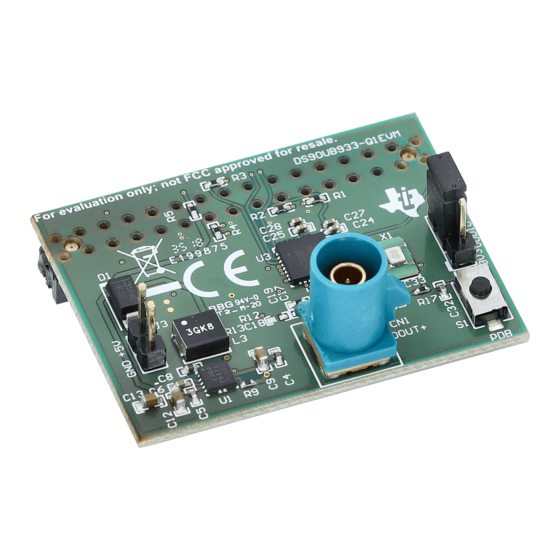
The Texas Instruments DS90UB933-Q1EVM Evaluation Module (EVM) provides an easy way to evaluate
the operation and performance of the DS90UB933-Q1 FPD-Link III Serializer.
Trademarks
All trademarks are the property of their respective owners.
1
Overview
Other components required: Power supply (12 V), 50-Ω coaxial cable, and a compatible deserializer board
such as DS90UB934.
Specification for orderable coax cable:
Water Blue, FAKRA Jack to FAKRA Jack Cable, 60-inch length, using RG174 Coax cable. EVM boards
have SMB connector mounted as shown in
(1)
Coax cable is not provided with the EVM.
(2)
Boards are configured to transmit power over coax cable, hence connect power to Deserializer board only.
(3)
Not a specific recommendation, for evaluation purpose only.
SNLU210B – July 2016 – Revised December 2017
Submit Documentation Feedback
DS90UB933-Q1EVM User's Guide
(1) (2)
Figure 1. DS90UB933-Q1EVM
(3)
Figure
Copyright © 2016–2017, Texas Instruments Incorporated
SNLU210B – July 2016 – Revised December 2017
1.
DS90UB933-Q1EVM User's Guide
1
Advertisement

Related Manuals for Texas Instruments DS90UB933-Q1EVM


Summary of Contents for Texas Instruments DS90UB933-Q1EVM
- Page 1 SNLU210B – July 2016 – Revised December 2017 DS90UB933-Q1EVM User's Guide The Texas Instruments DS90UB933-Q1EVM Evaluation Module (EVM) provides an easy way to evaluate the operation and performance of the DS90UB933-Q1 FPD-Link III Serializer. Trademarks All trademarks are the property of their respective owners.
- Page 2 If the LED is lit and stable, then the Deserializer is LOCKED to the FPD-Link III serial stream… CONGRATULATIONS, you are up and running! • If not, continue to the next section. DS90UB933-Q1EVM User's Guide SNLU210B – July 2016 – Revised December 2017 Submit Documentation Feedback Copyright © 2016–2017, Texas Instruments Incorporated...
- Page 3 10 bit mode (default mode) 50 MHz 12 bit high frequency mode 37.5 MHz 7. Go back to to double check factory settings. SNLU210B – July 2016 – Revised December 2017 DS90UB933-Q1EVM User's Guide Submit Documentation Feedback Copyright © 2016–2017, Texas Instruments Incorporated...
- Page 4 Board Setup Details This section describes the connectors and jumpers on the board as well as how to properly connect, set up and use the DS90UB933-Q1EVM in detail. Power Connections 1. Connect an external 12 V to the Deserializer board. (Refer to Deserializer's user guide for specific pins) 2.
- Page 5 J1 – GPO0, GPO1, CLK OUT, CLK IN, DIN[11:0], HSYNC, VSYNC, PCLK IN are the input pins for the LVCMOS interface on Serializer board. Refer to Figure 4 below. Figure 4. Parallel Input Connector on Serializer Board SNLU210B – July 2016 – Revised December 2017 DS90UB933-Q1EVM User's Guide Submit Documentation Feedback Copyright © 2016–2017, Texas Instruments Incorporated...
- Page 6 USB2ANY. The part number on the left may be different, or there may not be one, but the key is that it will say USB2ANY...' under Devices. In practice the DS90UB933-Q1EVM is programmed by the deserializer such as the DS90UB934 EVM. The deserializers typically have the USB2ANYs I2C programming functionality integrated into the EVM.
- Page 7 Expand the Tools panel and select USB2ANY/AArdvark Setup. If there is already a device listed n the menu, then select it and click Remove SNLU210B – July 2016 – Revised December 2017 DS90UB933-Q1EVM User's Guide Submit Documentation Feedback Copyright © 2016–2017, Texas Instruments Incorporated...
- Page 8 Once it has been removed (or if there wasn't one to begin with), select the EVM name from the list on the right and click Add. If you plan on using a deserializer to program the DS90UB933-Q1EVM, select the deserializer name if you have it connected instead.
- Page 9 Schematics www.ti.com Schematics Figure 6. DS90UB933-Q1 Serializer SNLU210B – July 2016 – Revised December 2017 DS90UB933-Q1EVM User's Guide Submit Documentation Feedback Copyright © 2016–2017, Texas Instruments Incorporated...
- Page 10 Schematics www.ti.com Figure 7. Power to Serializer Board and Header DS90UB933-Q1EVM User's Guide SNLU210B – July 2016 – Revised December 2017 Submit Documentation Feedback Copyright © 2016–2017, Texas Instruments Incorporated...
- Page 11 PCB Layout www.ti.com PCB Layout DS90UB933-Q1EVM Serializer Board Layout 1. DS90UB933-Q1EVM SNLU210B – July 2016 – Revised December 2017 DS90UB933-Q1EVM User's Guide Submit Documentation Feedback Copyright © 2016–2017, Texas Instruments Incorporated...
- Page 12 PCB Layout www.ti.com 2. TOP Layer DS90UB933-Q1EVM User's Guide SNLU210B – July 2016 – Revised December 2017 Submit Documentation Feedback Copyright © 2016–2017, Texas Instruments Incorporated...
- Page 13 PCB Layout www.ti.com 3. Signal 1 SNLU210B – July 2016 – Revised December 2017 DS90UB933-Q1EVM User's Guide Submit Documentation Feedback Copyright © 2016–2017, Texas Instruments Incorporated...
- Page 14 PCB Layout www.ti.com 4. Signal 2 DS90UB933-Q1EVM User's Guide SNLU210B – July 2016 – Revised December 2017 Submit Documentation Feedback Copyright © 2016–2017, Texas Instruments Incorporated...
- Page 15 PCB Layout www.ti.com 5. Bottom SNLU210B – July 2016 – Revised December 2017 DS90UB933-Q1EVM User's Guide Submit Documentation Feedback Copyright © 2016–2017, Texas Instruments Incorporated...
- Page 16 PCB Layout www.ti.com 6. Bottom with Overlay (Mirrored) DS90UB933-Q1EVM User's Guide SNLU210B – July 2016 – Revised December 2017 Submit Documentation Feedback Copyright © 2016–2017, Texas Instruments Incorporated...
- Page 17 DS90UB933-Q1EVM Serializer Board Bill of Materials www.ti.com DS90UB933-Q1EVM Serializer Board Bill of Materials Table 2. DS90UB933-Q1EVM BOM REFERENCE PART MFR and PART# FOOTPRINT C3, C8, C10, C17, C23, C31 0.1µF 0402 TDK C1005X7R1H104K050BB C1, C9, C12, C13, C22, C30 10µF...
- Page 18 Revised Top layer silkscreen to show CE mark............. • Revised BOM to include DNP components, R18,C15,C16,C21,C29......................• Changed layout to new format Revision History SNLU210B – July 2016 – Revised December 2017 Submit Documentation Feedback Copyright © 2016–2017, Texas Instruments Incorporated...
- Page 19 IMPORTANT NOTICE FOR TI DESIGN INFORMATION AND RESOURCES Texas Instruments Incorporated (‘TI”) technical, application or other design advice, services or information, including, but not limited to, reference designs and materials relating to evaluation modules, (collectively, “TI Resources”) are intended to assist designers who are developing applications that incorporate TI products;...
-
Page 20: Texas Instruments
Mouser Electronics Authorized Distributor Click to View Pricing, Inventory, Delivery & Lifecycle Information: Texas Instruments DS90UB933-Q1EVM...
Need help?
Do you have a question about the DS90UB933-Q1EVM and is the answer not in the manual?
Questions and answers