Advertisement
Quick Links
LIST OF FIGURES ....................................................................................................................................... 1
LIST OF TABLES ......................................................................................................................................... 1
1.
INTRODUCTION ............................................................................................................................. 2
1.1.
CONTENTS OF DS90UB925QSEVB ............................................................................................. 2
1.2.
HIGHLIGHTS OF EVB .................................................................................................................... 2
1.3.
OPERATION – QUICK SETUP ....................................................................................................... 3
1.4.
TROUBLE SHOOTING THE EVB ................................................................................................... 3
2.
BOARD SETUP DETAILS .............................................................................................................. 4
2.1.
POWER CONNECTIONS ................................................................................................................ 4
2.2.
FPD-LINK III CONNECTION ........................................................................................................... 4
2.3.
FACTORY SET SWITCH SETTINGS AND JUMPERS DEFAULT CONFIGURATION ................ 4
2.4.
LVCMOS INPUT CONNECTOR DESCRIPTION ............................................................................ 5
3.
APPENDIX – I2C, INTEGRATED SPA DONGLE .......................................................................... 6
3.1.
I2C SPA DONGLE HOOKUP .......................................................................................................... 6
3.2.
IDX BOARD DEFAULT ADDRESS ................................................................................................ 6
3.3.
ALP SOFTWARE SETUP ............................................................................................................... 7
3.3.1.
SYSTEM REQUIREMENTS ............................................................................................................ 7
3.3.2.
CD CONTENTS ............................................................................................................................... 7
3.3.3.
INSTALLATION OF THE ALP SOFTWARE .................................................................................. 7
3.3.4.
INSTALLATION OF THE USB DRIVER ......................................................................................... 8
3.3.5.
STARTUP - SOFTWARE DESCRIPTION ...................................................................................... 8
3.3.6.
TROUBLE SHOOTING ALP SOFTWARE ................................................................................... 15
4.
APPENDIX – USE OF OPTIONAL ROSENBERGER HSD CONNECTOR (J1) .......................... 18
5.
APPENDIX – USE OF OPTIONAL MINI-B USB CONNECTOR (J2)........................................... 18
6.
APPENDIX - BOARD LAYOUT .................................................................................................... 18
7.
SCHEMATIC .................................................................................................................................. 25
8.
BILL OF MATERIALS ................................................................................................................... 30
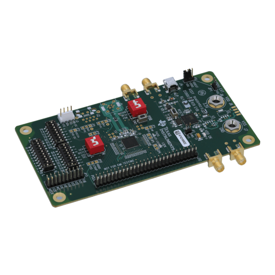
Figure 1: DS90UB925Q EVB ........................................................................................................................ 2
Figure 2: Factory Switch (S1,S2,S3,S4) and Jumper (JP2) Configuration ................................................... 5
Figure 3: Initial ALP Screen .......................................................................................................................... 9
Figure 4: TOP View ..................................................................................................................................... 19
Figure 5: BOTTOM View ............................................................................................................................. 20
Figure 6: TOP Layer ................................................................................................................................... 21
Figure 7: GND Layer ................................................................................................................................... 22
Figure 8: PWR Layer .................................................................................................................................. 23
Figure 9: BOTTOM Layer ........................................................................................................................... 24
Table 1: Bill of Materials .............................................................................................................................. 30
Sept 2012
DS90UB925QSEVB User's Guide
LIST OF FIGURES
LIST OF TABLES
User's Guide
DS90UB925QSEVB User's Guide
Sept 2012
1
Advertisement

Related Manuals for Texas Instruments DS90UB925QSEVB


Summary of Contents for Texas Instruments DS90UB925QSEVB
- Page 1 LIST OF FIGURES ............................1 LIST OF TABLES ............................1 INTRODUCTION ..........................2 1.1. CONTENTS OF DS90UB925QSEVB ..................... 2 1.2. HIGHLIGHTS OF EVB ........................2 1.3. OPERATION – QUICK SETUP ....................... 3 ...
- Page 2 Introduction The Texas Instruments DS90UB925QSEVB evaluation kit (EVB) provides an easy way to evaluate the operation and performance of the DS90UB925Q 2.975Gbps FPD-Link III serializer. 1.1. Contents of DS90UB925QSEVB 1- DS90UB925Q EVB, 1- CD with ALP software, 1- USB cable 1.2.
- Page 3 www.ti.com 1.3. Operation – Quick Setup Make sure S1, S2, S3, S4, and JP2 are configured as shown in Figure 1. 1) Turn on the deserializer. Typically this would be the DS90UB926Q EVB. 2) If interfacing to 3.3V LVCMOS, skip this step, otherwise: when interfacing to 1.8V LVCMOS inputs (upstream device), move factory jumper from pin-2/3 to pin 1 to connect to pin-1/2 and apply 1.8V power to pin 1 of JP1.
-
Page 4: Power Connections
The PDB switch is set HIGH and will turn on the DS90UB925Q upon power up. SW2 is a momentary switch. Instead of toggling switch 1 of S1 to do a PDB toggle, press SW2 to do a PDB toggle. DS90UB925QSEVB User’s Guide Sept 2012... - Page 5 www.ti.com 2) The S2 and S3 switches are factory set as shown below. All switches are set HIGH except 18 on S3. This sets IDx address to 18. Note only one switch is allowed LOW at a time. 3) The S4 switch is factory set as shown below. All switches are set HIGH except 1.
- Page 6 3. Appendix – I2C, integrated SPA Dongle 3.1. I2C SPA Dongle Hookup 3.3V Connect to PC with supplied USB cable FPD-Link III Output 3.2. IDx Board Default Address The IDx address on the EVB has been preset at 18. DS90UB925QSEVB User’s Guide Sept 2012...
- Page 7 www.ti.com ALP Software Setup 3.3. 3.3.1. System Requirements Operating System: Windows XP or Vista USB: 3.3.2. CD contents Extract the “ALPF_xxxxxxxx_xxx_xxxx.exe” file to a temporary location that can be deleted later. Make sure J4 on the DS90UB925 is connected to a PC USB port with the supplied USB cable and power is applied to the DS90UB925 EVB The following installation instructions are for the Windows XP Operating System.
- Page 8 Make sure all the software has been installed and the hardware is powered on and connected to the PC. Execute “Analog LaunchPAD” from the start menu. The default start menu location is “Programs\National Semiconductor Corp\Analog LaunchPAD vx.x.x\Analog LaunchPAD”. DS90UB925QSEVB User’s Guide Sept 2012...
- Page 9 www.ti.com The application should come up in the state shown in the figure below. If it does not, see “Trouble Shooting” at the end of this document. Under the Devices tab click on “DS90UB925” to select the device and open up the device profile and its associated tabs.
-
Page 10: Information Tab
The Information tab is shown below. Please note the device revision could be different. Appears only when deserializer is detected System Topology Tab The System Topology tab is shown below. Appears only when deserializer is detected DS90UB925QSEVB User’s Guide Sept 2012... - Page 11 www.ti.com SER Pattern Generator Tab The SER Pattern Generator tab is shown below. DES Pattern Generator Tab The DES Pattern Generator tab is shown below. Sept 2012 Literature Number: SNLU113...
-
Page 12: Registers Tab
Registers Tab The Registers tab is shown below. Registers Tab – Address 0x00 selected Address 0x00 selected as shown below. Note that the “Value:” box, , will now show the hex value of that register. DS90UB925QSEVB User’s Guide Sept 2012... - Page 13 www.ti.com Registers Tab – Address 0x00 expanded By double clicking on the Address bar or a single click on Address 0x00 expanded reveals contents by bits. Any register address displayed can be expanded. Any RW Type register, , can be written into by writing the hex value into the “Value:” box, or putting the pointer into the individual register bit(s) box by a left mouse click to put a check mark (indicating a “1”) or unchecking to remove the check mark (indicating a “0”).
- Page 14 Either enter “DE” in the value box or toggle bit 7 to enable I2C PASS ALL. Click for the register value to be written into register. Do not select I2C PASS ALL on deserializer side if enabled on serializer side. DS90UB925QSEVB User’s Guide Sept 2012...
-
Page 15: Scripting Tab
www.ti.com Scripting Tab The Scripting tab is shown below. Usage is not described in this document. 3.3.6. Trouble Shooting ALP Software If the following window opens after starting the ALP software, double check the hardware setup. Analog LaunchPAD No Devices Error It may also be that the USB driver is not installed. - Page 16 If there are more devices then the software is most likely in demo mode. When the ALP is operating in demo mode there is a “(Demo Mode)” indication in the lower left of the application status bar as shown below. DS90UB925QSEVB User’s Guide Sept 2012...
- Page 17 www.ti.com Analog LaunchPAD in Demo Mode Disable the demo mode by selecting the “Preferences” pull down menu and un- checking “Enable Demo Mode”. Analog LaunchPAD Preferences Menu After demo mode is disabled, the ALP software will poll the ALP hardware. The ALP software will update and have only “DS90UB925Q”...
- Page 18 The DS90UB925Q is a 4-layer board (TOP / GND / PWR / BOTTOM). The 50Ω microstrip trace on the top layer of the board is referenced to GND, and the 100Ω differential traces are referenced to GND. DS90UB925QSEVB User’s Guide Sept 2012...
- Page 19 www.ti.com Figure 4: TOP View Sept 2012 Literature Number: SNLU113...
- Page 20 Figure 5: BOTTOM View DS90UB925QSEVB User’s Guide Sept 2012...
- Page 21 www.ti.com Figure 6: TOP Layer Sept 2012 Literature Number: SNLU113...
- Page 22 Figure 7: GND Layer DS90UB925QSEVB User’s Guide Sept 2012...
- Page 23 www.ti.com Figure 8: PWR Layer Sept 2012 Literature Number: SNLU113...
- Page 24 Figure 9: BOTTOM Layer DS90UB925QSEVB User’s Guide Sept 2012...
- Page 25 www.ti.com 7. Schematic Sept 2012 Literature Number: SNLU113...
- Page 26 DS90UB925QSEVB User’s Guide Sept 2012...
- Page 27 www.ti.com Sept 2012 Literature Number: SNLU113...
- Page 28 DS90UB925QSEVB User’s Guide Sept 2012...
- Page 29 www.ti.com Sept 2012 Literature Number: SNLU113...
-
Page 30: Bill Of Materials
Schematic 8. Bill of Materials Table 1: Bill of Materials DS90UB925QSEVB User’s Guide Sept 2012... - Page 31 EVALUATION BOARD/KIT/MODULE (EVM) ADDITIONAL TERMS Texas Instruments (TI) provides the enclosed Evaluation Board/Kit/Module (EVM) under the following conditions: The user assumes all responsibility and liability for proper and safe handling of the goods. Further, the user indemnifies TI from all claims arising from the handling or use of the goods.
- Page 32 This equipment has been tested and found to comply with the limits for a Class A digital device, pursuant to part 15 of the FCC Rules. These limits are designed to provide reasonable protection against harmful interference when the equipment is operated in a commercial environment. This equipment generates, uses, and can radiate radio frequency energy and, if not installed and used in accordance with the instruction manual, may cause harmful interference to radio communications.
- Page 33 Please note that if you could not follow the instructions above, you will be subject to penalties of Radio Law of Japan. Texas Instruments Japan Limited (address) 24-1, Nishi-Shinjuku 6 chome, Shinjuku-ku, Tokyo, Japan http://www.tij.co.jp...
- Page 34 FDA Class III or similar classification, then you must specifically notify TI of such intent and enter into a separate Assurance and Indemnity Agreement. Mailing Address: Texas Instruments, Post Office Box 655303, Dallas, Texas 75265 Copyright © 2012, Texas Instruments Incorporated...
- Page 35 IMPORTANT NOTICE Texas Instruments Incorporated and its subsidiaries (TI) reserve the right to make corrections, enhancements, improvements and other changes to its semiconductor products and services per JESD46, latest issue, and to discontinue any product or service per JESD48, latest issue.
-
Page 36: Texas Instruments
Mouser Electronics Authorized Distributor Click to View Pricing, Inventory, Delivery & Lifecycle Information: Texas Instruments DS90UB925QSEVB/NOPB...
Need help?
Do you have a question about the DS90UB925QSEVB and is the answer not in the manual?
Questions and answers