Table of Contents
Advertisement
Quick Links
www.ti.com
User's Guide
DS90UB95x-Q1 Serializer Evaluation Module
Ankur Verma, Cole Macias
The Texas Instruments DS90UB95x-Q1EVM evaluation module (EVM) is a functional board design for
evaluating the DS90UB953-Q1 FPD-Link III serializer and the TSER953 V
provides necessary details for the evaluation such as a brief product overview, quick-start guide, troubleshooting
section, schematics, and printed-circuit board (PCB) layout details, and bill of materials (BOM).
The DS90UB953-Q1 and TSER953 serializers represent the next generation in FPD-Link III and V
serializers and are designed to support high-speed raw data sensors including 2-MP imagers at 60 fps, as
well as 4-MP, 30-fps cameras, satellite RADAR, LIDAR, and time-of-flight (ToF) sensors. The chip delivers a
4-Gbps+ forward channel and an ultra-low latency, 50-Mbps bidirectional control channel. The chip also supports
power over a single coax (PoC) or shielded twisted-pair (STP) cable and connector. The DS90UB953-Q1 and
TSER953 feature advanced data protection and diagnostic features to support ADAS, autonomous driving, and
industrial and medical imaging applications. Together with a companion deserializer, the chip delivers precise
multi-camera sensor clock and sensor synchronization. For a full list of device characteristics, refer to the
DS90UB953-Q1
and
TSER953
1
Introduction.............................................................................................................................................................................3
Guide....................................................................................................................................................................4
3
Troubleshooting......................................................................................................................................................................7
4 Bill of Materials.....................................................................................................................................................................
5 PCB Schematics...................................................................................................................................................................
Layout.........................................................................................................................................................................47
Documentation........................................................................................................................................................53
8 Revision History...................................................................................................................................................................
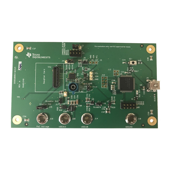
Figure 1-1. DS90UB95x-Q1EVM Top View.................................................................................................................................
Figure 2-2. DS90UB95x-Q1EVM Major Components.................................................................................................................
Figure 2-3. DS90UB95x-Q1EVM With Installed Jumpers...........................................................................................................
Figure 2-4. DS90UB954-Q1EVM (or variant) With Jumpers Highlighted....................................................................................
USB2ANY..................................................................................................................................................................7
Figure 3-2. I2C Pinout of USB2ANY Connector..........................................................................................................................
Figure 3-3. Launching ALP........................................................................................................................................................
Screen....................................................................................................................................................10
Figure 3-5. Follow-Up Screen....................................................................................................................................................
Tab...................................................................................................................................................13
Figure 3-8. ALP Device ID Selected..........................................................................................................................................
Expanded........................................................................................................................................15
Figure 3-10. Writing to Register 0x00 by Checking Bits in
Figure 3-11. ALP Scripting Tab..................................................................................................................................................
Figure 3-12. Pre-Defined Scripts...............................................................................................................................................
Tab..................................................................................................................................................21
SNLU224C - SEPTEMBER 2017 - REVISED APRIL 2021
Submit Document Feedback
ABSTRACT
product folders.
Table of Contents
List of Figures
Tab................................................................................................................................................12
1.............................................................................................................................18
2.............................................................................................................................18
Copyright © 2021 Texas Instruments Incorporated
3
Link serializer. This document
ALP.................................................................................................15
DS90UB95x-Q1 Serializer Evaluation Module
Table of Contents
3
Link
variant)...................................4
39
43
53
3
5
5
6
8
10
11
14
16
17
1
Advertisement
Table of Contents

Related Manuals for Texas Instruments DS90UB95x-Q1


Summary of Contents for Texas Instruments DS90UB95x-Q1
-
Page 1: Table Of Contents
DS90UB95x-Q1 Serializer Evaluation Module Ankur Verma, Cole Macias ABSTRACT The Texas Instruments DS90UB95x-Q1EVM evaluation module (EVM) is a functional board design for evaluating the DS90UB953-Q1 FPD-Link III serializer and the TSER953 V Link serializer. This document provides necessary details for the evaluation such as a brief product overview, quick-start guide, troubleshooting section, schematics, and printed-circuit board (PCB) layout details, and bill of materials (BOM). - Page 2 List of Tables Table 3-1. Equipment.................................31 Table 4-1. Bill of Materials................................39 Trademarks All trademarks are the property of their respective owners. DS90UB95x-Q1 Serializer Evaluation Module SNLU224C – SEPTEMBER 2017 – REVISED APRIL 2021 Submit Document Feedback Copyright © 2021 Texas Instruments Incorporated...
-
Page 3: Introduction
Figure 1-1. DS90UB95x-Q1EVM Top View SNLU224C – SEPTEMBER 2017 – REVISED APRIL 2021 DS90UB95x-Q1 Serializer Evaluation Module Submit Document Feedback Copyright © 2021 Texas Instruments Incorporated... -
Page 4: Quick Start Guide
50 Ÿ 50 Ÿ HS_GPIO HS_GPIO (SPI) (SPI) Figure 2-1. Typical Application Block Diagram Using DS90UB953-Q1 and DS90UB954-Q1 (or variant) DS90UB95x-Q1 Serializer Evaluation Module SNLU224C – SEPTEMBER 2017 – REVISED APRIL 2021 Submit Document Feedback Copyright © 2021 Texas Instruments Incorporated... -
Page 5: Figure 2-2. Ds90Ub95X-Q1Evm Major Components
1. Ensure jumpers on J2, J4, and J15 for DS90UB95x-Q1EVM are installed as shown in Figure 2-3 Figure 2-3. DS90UB95x-Q1EVM With Installed Jumpers SNLU224C – SEPTEMBER 2017 – REVISED APRIL 2021 DS90UB95x-Q1 Serializer Evaluation Module Submit Document Feedback Copyright © 2021 Texas Instruments Incorporated... -
Page 6: Figure 2-4. Ds90Ub954-Q1Evm (Or Variant) With Jumpers Highlighted
The only modification required to use the DS90UB95x-Q1EVM to evaluate the DS90UB935-Q1 is to exchange the DS90UB953-Q1 with the DS90UB935-Q1. No additional rework is required. DS90UB95x-Q1 Serializer Evaluation Module SNLU224C – SEPTEMBER 2017 – REVISED APRIL 2021 Submit Document Feedback Copyright © 2021 Texas Instruments Incorporated... -
Page 7: Troubleshooting
USB2ANY pinout with the I2C pins highlighted. Typically, jumper wires are used to connect these to the 953/954 EVMs. SNLU224C – SEPTEMBER 2017 – REVISED APRIL 2021 DS90UB95x-Q1 Serializer Evaluation Module Submit Document Feedback Copyright © 2021 Texas Instruments Incorporated... -
Page 8: Figure 3-2. I2C Pinout Of Usb2Any Connector
Save the script, close the program, and ALP will now recognize the connection from the board to the USB2ANY. DS90UB95x-Q1 Serializer Evaluation Module SNLU224C – SEPTEMBER 2017 – REVISED APRIL 2021 Submit Document Feedback Copyright © 2021 Texas Instruments Incorporated... - Page 9 Make sure all the software has been installed and the hardware is powered on and connected to the PC. Execute Analog LaunchPAD shortcut from the start menu. The default start menu location is under All Programs > Texas Instruments > Analog LaunchPAD vx.x.x > Analog LaunchPAD to start MainGUI.exe. SNLU224C – SEPTEMBER 2017 – REVISED APRIL 2021...
-
Page 10: Figure 3-3. Launching Alp
3.4.1. Figure 3-4. Initial ALP Screen After selecting the DS90UB95x, the following screen shown in Figure 3-5 should appear. DS90UB95x-Q1 Serializer Evaluation Module SNLU224C – SEPTEMBER 2017 – REVISED APRIL 2021 Submit Document Feedback Copyright © 2021 Texas Instruments Incorporated... -
Page 11: Figure 3-5. Follow-Up Screen
Troubleshooting Figure 3-5. Follow-Up Screen SNLU224C – SEPTEMBER 2017 – REVISED APRIL 2021 DS90UB95x-Q1 Serializer Evaluation Module Submit Document Feedback Copyright © 2021 Texas Instruments Incorporated... -
Page 12: Figure 3-6. Alp Information Tab
Troubleshooting www.ti.com 3.3.5 Information Tab The Information tab is shown in Figure 3-6. Figure 3-6. ALP Information Tab DS90UB95x-Q1 Serializer Evaluation Module SNLU224C – SEPTEMBER 2017 – REVISED APRIL 2021 Submit Document Feedback Copyright © 2021 Texas Instruments Incorporated... -
Page 13: Figure 3-7. Alp Registers Tab
Troubleshooting 3.3.6 Registers Tab The Register tab is shown in Figure 3-7. Figure 3-7. ALP Registers Tab SNLU224C – SEPTEMBER 2017 – REVISED APRIL 2021 DS90UB95x-Q1 Serializer Evaluation Module Submit Document Feedback Copyright © 2021 Texas Instruments Incorporated... -
Page 14: Figure 3-8. Alp Device Id Selected
Address 0x00 selected. Note that the Value: box, , will now show the hex value of that register. Figure 3-8. ALP Device ID Selected DS90UB95x-Q1 Serializer Evaluation Module SNLU224C – SEPTEMBER 2017 – REVISED APRIL 2021 Submit Document Feedback Copyright © 2021 Texas Instruments Incorporated... -
Page 15: Figure 3-9. Alp Device Id Expanded
(highlighted) register. Figure 3-10. Writing to Register 0x00 by Checking Bits in ALP The box toggles on every mouse click. SNLU224C – SEPTEMBER 2017 – REVISED APRIL 2021 DS90UB95x-Q1 Serializer Evaluation Module Submit Document Feedback Copyright © 2021 Texas Instruments Incorporated... -
Page 16: Figure 3-11. Alp Scripting Tab
Scripting tab or may be run from a .py file using the "Run" button. Example scripts may be found using the "Run PreDef Script" button. Figure 3-11. ALP Scripting Tab DS90UB95x-Q1 Serializer Evaluation Module SNLU224C – SEPTEMBER 2017 – REVISED APRIL 2021 Submit Document Feedback Copyright © 2021 Texas Instruments Incorporated... -
Page 17: Figure 3-12. Pre-Defined Scripts
"Setup" button, then say "Add", and select the desired name and script. To make the button appear in future instances of ALP, click the "Set As Default" button. SNLU224C – SEPTEMBER 2017 – REVISED APRIL 2021 DS90UB95x-Q1 Serializer Evaluation Module Submit Document Feedback Copyright © 2021 Texas Instruments Incorporated... -
Page 18: Figure 3-13. Custom Button Creation Step 1
ALP Framework application. 3.3.9.1 Example Functions The following are Python functions commonly used to interact with FPD-Link devices. DS90UB95x-Q1 Serializer Evaluation Module SNLU224C – SEPTEMBER 2017 – REVISED APRIL 2021 Submit Document Feedback Copyright © 2021 Texas Instruments Incorporated... - Page 19 Ex: board.WriteI2C(0x60, 0x01, 0x01) will set Register 1 of the device with address 0x60 (8-bit form) to have a value of 1 SNLU224C – SEPTEMBER 2017 – REVISED APRIL 2021 DS90UB95x-Q1 Serializer Evaluation Module Submit Document Feedback Copyright © 2021 Texas Instruments Incorporated...
- Page 20 • Ex: board.WriteI2C(0x60, 0x30, [0x01, 0x01]) will set Register 0x3000 of the device with address 0x60 (8-bit form) to have a value of 1 DS90UB95x-Q1 Serializer Evaluation Module SNLU224C – SEPTEMBER 2017 – REVISED APRIL 2021 Submit Document Feedback Copyright © 2021 Texas Instruments Incorporated...
-
Page 21: Figure 3-15. Alp Scripting Tab
ALP Framework application. SNLU224C – SEPTEMBER 2017 – REVISED APRIL 2021 DS90UB95x-Q1 Serializer Evaluation Module Submit Document Feedback Copyright © 2021 Texas Instruments Incorporated... -
Page 22: Figure 3-16. Usb2Any Setup
Figure 3-17. Remove Incorrect Profile Find the correct profile under the Select a Daughter Board list, highlight the profile and press Add. DS90UB95x-Q1 Serializer Evaluation Module SNLU224C – SEPTEMBER 2017 – REVISED APRIL 2021 Submit Document Feedback Copyright © 2021 Texas Instruments Incorporated... -
Page 23: Figure 3-18. Add Correct Profile
Figure 3-18. Add Correct Profile Select Ok and the correct profile should now be loaded. Figure 3-19. Finish Setup SNLU224C – SEPTEMBER 2017 – REVISED APRIL 2021 DS90UB95x-Q1 Serializer Evaluation Module Submit Document Feedback Copyright © 2021 Texas Instruments Incorporated... -
Page 24: Figure 3-20. Alp No Devices Error
It may also be that the USB2ANY driver is not installed. Check the device manager. There should be a HID-compliant device under the Human Interface Devices as shown below. Figure 3-21. Windows 7, ALP USB2ANY Driver DS90UB95x-Q1 Serializer Evaluation Module SNLU224C – SEPTEMBER 2017 – REVISED APRIL 2021 Submit Document Feedback Copyright © 2021 Texas Instruments Incorporated... -
Page 25: Figure 3-22. Alp In Demo Mode
After demo mode is disabled, the ALP software will poll the ALP hardware. The ALP software will update and have only DS90UB95x under the Devices drop-down menu. SNLU224C – SEPTEMBER 2017 – REVISED APRIL 2021 DS90UB95x-Q1 Serializer Evaluation Module Submit Document Feedback Copyright © 2021 Texas Instruments Incorporated... -
Page 26: Figure 3-24. Error That States One Instance Of This Application Can Be Active In Alp
You should now be able to open ALP normally. If the problem persists, restart your machine and follow the steps again. DS90UB95x-Q1 Serializer Evaluation Module SNLU224C – SEPTEMBER 2017 – REVISED APRIL 2021 Submit Document Feedback Copyright © 2021 Texas Instruments Incorporated... -
Page 27: Figure 3-26. Error That States That Usb2Any Firmware Must Be
By default, the program will be located in the bin folder of the TI USB2ANY SDK folder (for example, C:\Program Files (x86)\TI USB2ANY SDK\bin). The program dialog will look like this: SNLU224C – SEPTEMBER 2017 – REVISED APRIL 2021 DS90UB95x-Q1 Serializer Evaluation Module Submit Document Feedback Copyright © 2021 Texas Instruments Incorporated... -
Page 28: Figure 3-27. Usb2Any Firmware Loader Program Dialog
If the USB2ANY is in an enclosure, you will need to insert an implement (a paper clip works great) into the small hole to press the button. DS90UB95x-Q1 Serializer Evaluation Module SNLU224C – SEPTEMBER 2017 – REVISED APRIL 2021 Submit Document Feedback Copyright © 2021 Texas Instruments Incorporated... -
Page 29: Figure 3-28. Usb2Any Without Enclosure
953 by double clicking the name. Select the registers tab, click register 0x00 label I2C_DEVICE_ID, and read the value, shown in Figure 3-30. SNLU224C – SEPTEMBER 2017 – REVISED APRIL 2021 DS90UB95x-Q1 Serializer Evaluation Module Submit Document Feedback Copyright © 2021 Texas Instruments Incorporated... -
Page 30: Figure 3-30. Verifying Ds90Ub95X Register
When done saving and adding scripts, press OK. The buttons should be added to the right-hand side of the window under the Setup and Run buttons in the script tab. DS90UB95x-Q1 Serializer Evaluation Module SNLU224C – SEPTEMBER 2017 – REVISED APRIL 2021 Submit Document Feedback Copyright © 2021 Texas Instruments Incorporated... -
Page 31: Table 3-1. Equipment
Banana to Coaxial cable banana to male coax information in step 5 of Section 2.4). SNLU224C – SEPTEMBER 2017 – REVISED APRIL 2021 DS90UB95x-Q1 Serializer Evaluation Module Submit Document Feedback Copyright © 2021 Texas Instruments Incorporated... - Page 32 9. Connect the Mini USB to USB cable from J9 on the DS90UB953EVM to the computer that will use Analog Launch Pad (ALP). DS90UB95x-Q1 Serializer Evaluation Module SNLU224C – SEPTEMBER 2017 – REVISED APRIL 2021 Submit Document Feedback Copyright © 2021 Texas Instruments Incorporated...
-
Page 33: Figure 3-32. Ds90Ub954-Q1Evm (Or Variant) With Highlighted Jumpers
10. On the DS90UB954EVM (or variant), ensure that all jumpers are correctly covering the headers highlighted Figure 3-32. Figure 3-32. DS90UB954-Q1EVM (or variant) With Highlighted Jumpers SNLU224C – SEPTEMBER 2017 – REVISED APRIL 2021 DS90UB95x-Q1 Serializer Evaluation Module Submit Document Feedback Copyright © 2021 Texas Instruments Incorporated... -
Page 34: Figure 3-33. Ds90Ub95X-Q1Evm With Installed Jumpers
VDD3V3, and VDD1V8 using a Digital Multi-meter (DMM). The voltages should approximately read ≥7 V, 3.3 V, and 1.8 V, respectively. DS90UB95x-Q1 Serializer Evaluation Module SNLU224C – SEPTEMBER 2017 – REVISED APRIL 2021 Submit Document Feedback Copyright © 2021 Texas Instruments Incorporated... -
Page 35: Figure 3-34. Test Setup
Troubleshooting 14. The setup should now look like what is shown in the Figure 3-34. Figure 3-34. Test Setup SNLU224C – SEPTEMBER 2017 – REVISED APRIL 2021 DS90UB95x-Q1 Serializer Evaluation Module Submit Document Feedback Copyright © 2021 Texas Instruments Incorporated... -
Page 36: Figure 3-35. Setting Up Device Profiles In Alp
Section 3.4.6. Otherwise, you can run scripts by clicking the Run button and navigating to their file location. DS90UB95x-Q1 Serializer Evaluation Module SNLU224C – SEPTEMBER 2017 – REVISED APRIL 2021 Submit Document Feedback Copyright © 2021 Texas Instruments Incorporated... -
Page 37: Figure 3-37. Reading I2C Device Id Within The Register Tab
3. If you would like to place the scripts in the default ALP script folder, move them to the file location: SPACER C:\Program Files (x86)\Texas Instruments\Analog LaunchPAD 1.56.0010 SPACER 4. Verify there is successful local I2C communication that the script worked by going to the register tab,... -
Page 38: Figure 3-39. Verifying Camera Initialization In Alp
DC power supply, the HP E3610, is sourcing more current. Figure 3-39. Verifying Camera Initialization in ALP DS90UB95x-Q1 Serializer Evaluation Module SNLU224C – SEPTEMBER 2017 – REVISED APRIL 2021 Submit Document Feedback Copyright © 2021 Texas Instruments Incorporated... -
Page 39: Bill Of Materials
Q200 Grade 1, 0805 C43, C52, C58 4.7uF CAP, CERM, 4.7 µF, 16 V, +/- 10%, X7R, 0805_HV GRM21BR71C475KA73L MuRata 0805 SNLU224C – SEPTEMBER 2017 – REVISED APRIL 2021 DS90UB95x-Q1 Serializer Evaluation Module Submit Document Feedback Copyright © 2021 Texas Instruments Incorporated... - Page 40 Ferrite Bead, 330 ohm @ 100 MHz, 0.7 A, 0402 MPZ1005S331ETD25 0402 L6, R4, R5 RES, 0, 5%, 0.1 W, 0603 0603 CRCW06030000Z0EA Vishay-Dale DS90UB95x-Q1 Serializer Evaluation Module SNLU224C – SEPTEMBER 2017 – REVISED APRIL 2021 Submit Document Feedback Copyright © 2021 Texas Instruments Incorporated...
- Page 41 TPD4E004DRYR Texas Instruments Interfaces, 4 Channels, -40 to +85 degC, 6- pin SON (DRY), Green (RoHS & no Sb/Br) SNLU224C – SEPTEMBER 2017 – REVISED APRIL 2021 DS90UB95x-Q1 Serializer Evaluation Module Submit Document Feedback Copyright © 2021 Texas Instruments Incorporated...
- Page 42 OSC, 50MHz, 1.8 to 3.3V, SMD Abracon_ASDMB ASDMB-50.000MHZ-LC-T Abracon Corportation Crystal, 24 MHz, 18 pF, SMD XTAL_ABM3 ABM3-24.000MHZ-D2Y-T Abracon Corporation DS90UB95x-Q1 Serializer Evaluation Module SNLU224C – SEPTEMBER 2017 – REVISED APRIL 2021 Submit Document Feedback Copyright © 2021 Texas Instruments Incorporated...
-
Page 43: Pcb Schematics
10µF 40.2k LM53600AQDSXRQ1 0.01µF IMG_GP2 GPIO1 VSYNC 4700pF 4700pF 4700pF 4700pF POC_SENSE GPIO0 HSYNC Figure 5-1. DS90UB95x-Q1EVM Schematic 1 SNLU224C – SEPTEMBER 2017 – REVISED APRIL 2021 DS90UB95x-Q1 Serializer Evaluation Module Submit Document Feedback Copyright © 2021 Texas Instruments Incorporated... -
Page 44: Figure 5-2. Ds90Ub95X-Q1Evm Schematic 2
3.3V I2C 10.0k 40.2k VCCA VCCB VDD1V8 TCA9406DCUR 10.0k VDD3V3 10.0k 1µF IDx/CLK_OUT MODE Figure 5-2. DS90UB95x-Q1EVM Schematic 2 DS90UB95x-Q1 Serializer Evaluation Module SNLU224C – SEPTEMBER 2017 – REVISED APRIL 2021 Submit Document Feedback Copyright © 2021 Texas Instruments Incorporated... -
Page 45: Figure 5-3. Ds90Ub95X-Q1Evm Schematic 3
CSID0_N CSID1_P CSID1_N CSID2_P CSID2_N CSID3_P CSID3_N Imager_RESET IMG_GP4 Imager_PWDN IMG_GP5 IMG_GP2 IMG_GP6 IMG_GP3 Figure 5-3. DS90UB95x-Q1EVM Schematic 3 SNLU224C – SEPTEMBER 2017 – REVISED APRIL 2021 DS90UB95x-Q1 Serializer Evaluation Module Submit Document Feedback Copyright © 2021 Texas Instruments Incorporated... -
Page 46: Figure 5-4. Ds90Ub95X-Q1Evm Schematic 4
VSSU VUSB AVSS1 +3.3V AVCC1 AVSS2 DVCC1 DVSS1 DVCC2 DVSS2 2200pF MSP430F5529IPN 0.1µF 0.1µF Figure 5-4. DS90UB95x-Q1EVM Schematic 4 DS90UB95x-Q1 Serializer Evaluation Module SNLU224C – SEPTEMBER 2017 – REVISED APRIL 2021 Submit Document Feedback Copyright © 2021 Texas Instruments Incorporated... -
Page 47: Board Layout
The board layout for the DS90UB95x-Q1EVM is shown in Figure 6-1 through Figure 6-12. Figure 6-1. Top Layer PCB Layout Figure 6-2. Top Overlay SNLU224C – SEPTEMBER 2017 – REVISED APRIL 2021 DS90UB95x-Q1 Serializer Evaluation Module Submit Document Feedback Copyright © 2021 Texas Instruments Incorporated... -
Page 48: Figure 6-3. Top Paste
Board Layout www.ti.com Figure 6-3. Top Paste Figure 6-4. Top Solder DS90UB95x-Q1 Serializer Evaluation Module SNLU224C – SEPTEMBER 2017 – REVISED APRIL 2021 Submit Document Feedback Copyright © 2021 Texas Instruments Incorporated... -
Page 49: Figure 6-5. Signal Layer 1
Board Layout Figure 6-5. Signal Layer 1 Figure 6-6. Signal Layer 2 SNLU224C – SEPTEMBER 2017 – REVISED APRIL 2021 DS90UB95x-Q1 Serializer Evaluation Module Submit Document Feedback Copyright © 2021 Texas Instruments Incorporated... -
Page 50: Figure 6-7. Signal Layer 3
Board Layout www.ti.com Figure 6-7. Signal Layer 3 Figure 6-8. Signal Layer 4 DS90UB95x-Q1 Serializer Evaluation Module SNLU224C – SEPTEMBER 2017 – REVISED APRIL 2021 Submit Document Feedback Copyright © 2021 Texas Instruments Incorporated... -
Page 51: Figure 6-9. Bottom Layer Pcb Layout
Board Layout Figure 6-9. Bottom Layer PCB Layout Figure 6-10. Bottom Overlay SNLU224C – SEPTEMBER 2017 – REVISED APRIL 2021 DS90UB95x-Q1 Serializer Evaluation Module Submit Document Feedback Copyright © 2021 Texas Instruments Incorporated... -
Page 52: Figure 6-11. Bottom Paste
Board Layout www.ti.com Figure 6-11. Bottom Paste Figure 6-12. Bottom Solder DS90UB95x-Q1 Serializer Evaluation Module SNLU224C – SEPTEMBER 2017 – REVISED APRIL 2021 Submit Document Feedback Copyright © 2021 Texas Instruments Incorporated... -
Page 53: Related Documentation
Changes from Revision B (September 2020) to Revision C (April 2021) Page • Updated Abstract section to include V Link TSER953..................• Added link to TSER953 product page......................SNLU224C – SEPTEMBER 2017 – REVISED APRIL 2021 DS90UB95x-Q1 Serializer Evaluation Module Submit Document Feedback Copyright © 2021 Texas Instruments Incorporated... - Page 54 TI products. TI’s provision of these resources does not expand or otherwise alter TI’s applicable warranties or warranty disclaimers for TI products. TI objects to and rejects any additional or different terms you may have proposed. IMPORTANT NOTICE Mailing Address: Texas Instruments, Post Office Box 655303, Dallas, Texas 75265 Copyright © 2022, Texas Instruments Incorporated...
Need help?
Do you have a question about the DS90UB95x-Q1 and is the answer not in the manual?
Questions and answers