Table of Contents
Advertisement
Quick Links
The Texas Instruments DS90UB95x-Q1EVM evaluation modules (EVM) are functional board designs for
evaluating the DS90UB95x-Q1 FPD-Link III deserializers, which convert serialized camera data to MIPI
CSI-2 for processing. The MIPI CSI-2 output has four available lanes, and can be configured for either
four-lane output or replicated two-lane output. When paired with a compatible serializer, the deserializers
receive data from imager(s) supporting cameras as well as satellite RADAR. The DS90UB954-Q1 also
supports DS90UB913A/933 serializers.
Some variants are single channel; for these variants ignore references to RX1. Some references are
made to serializer backward compatibility; refer to the product datasheet for serializer compatibility.
The DS90UB954-Q1EVM is configured for communication with a DS90UB953-Q1 on channel 0 (RX0),
and a DS90UB933-Q1 on channel 1 (RX1). The EVM has two Rosenberger FAKRA connectors and
configurable Power-over-Coax (PoC) voltage for connecting the camera modules (not included). FPD-Link
III interfaces also include a separate low latency bidirectional control channel that conveys control
information from an I
synchronization and functional safety features also make use of this bidirectional control channel to
program registers in the DS90UB954-Q1 as well as the connected serializer and any remote I2C
connected devices. There is an onboard MSP430 which functions as a USB2ANY bridge for interfacing
with a PC for evaluation. The USB2ANY interfaces with the
...................................................................................................................
1
2
3
4
5
6
7
8
9
10
11
12
13
14
15
16
1
2
3
4
5
6
7
8
SNLU223A - August 2017 - Revised May 2019
Submit Documentation Feedback
DS90UB95x-Q1EVM Deserializer User's Guide
2
C port. General purpose I/O signals such as those required for camera
............................................................................................................
..........................................................................................................
.................................................................................................
................................................................................
........................................................................................................
.........................................................................................................
....................................................................................................
..........................................................................................................
......................................................................................
...........................................................................................
.......................................................................................
...................................................................................
.......................................................................................................
........................................................................................................
......................................................................................................
........................................................................................
...........................................................................................
Copyright © 2017-2019, Texas Instruments Incorporated
SNLU223A - August 2017 - Revised May 2019
Analog LaunchPAD
..............................................................................
List of Figures
.........................................................................
.................................................................
.................................................................
DS90UB95x-Q1EVM Deserializer User's Guide
User's Guide
GUI tool.
12
12
13
13
13
14
14
.....................
15
20
36
......
39
47
57
13
16
3
4
6
3
4
5
6
7
8
1
Advertisement
Table of Contents

Subscribe to Our Youtube Channel
Related Manuals for Texas Instruments DS90UB95 Q1EVM Series


Summary of Contents for Texas Instruments DS90UB95 Q1EVM Series
-
Page 1: Table Of Contents
SNLU223A – August 2017 – Revised May 2019 DS90UB95x-Q1EVM Deserializer User's Guide The Texas Instruments DS90UB95x-Q1EVM evaluation modules (EVM) are functional board designs for evaluating the DS90UB95x-Q1 FPD-Link III deserializers, which convert serialized camera data to MIPI CSI-2 for processing. The MIPI CSI-2 output has four available lanes, and can be configured for either four-lane output or replicated two-lane output. - Page 2 Layer 8: Bottom Signal Layer ....................Bottom View Composite List of Tables ........................ Power Supply ..............Power-over-Coax Power Supply Feed Configuration DS90UB95x-Q1EVM Deserializer User's Guide SNLU223A – August 2017 – Revised May 2019 Submit Documentation Feedback Copyright © 2017–2019, Texas Instruments Incorporated...
-
Page 3: Contents 1 Introduction
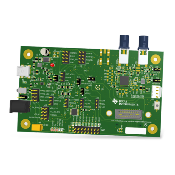
Figure 1. DS90UB95x-Q1EVM SNLU223A – August 2017 – Revised May 2019 DS90UB95x-Q1EVM Deserializer User's Guide Submit Documentation Feedback Copyright © 2017–2019, Texas Instruments Incorporated... -
Page 4: Quick Start Guide
3.2 Gbps Serializer MIPI CSI-2 Host / ISP 1.6 Gbps/lane X 4 DS90UB933 RAW 10/12 Serializer Figure 2. Applications Diagram DS90UB95x-Q1EVM Deserializer User's Guide SNLU223A – August 2017 – Revised May 2019 Submit Documentation Feedback Copyright © 2017–2019, Texas Instruments Incorporated... -
Page 5: Interfacing To The Evm
Quick Start Guide www.ti.com Major Components of DS90UB95x-Q1EVM Figure 3. Interfacing to the EVM SNLU223A – August 2017 – Revised May 2019 DS90UB95x-Q1EVM Deserializer User's Guide Submit Documentation Feedback Copyright © 2017–2019, Texas Instruments Incorporated... -
Page 6: Ds90Ub95X-Q1Evm Board Configuration
Reference Signal Description Main Power J1/J3 +12V Single +12VDC (nominal) power connector that supplies power to the entire board. DS90UB95x-Q1EVM Deserializer User's Guide SNLU223A – August 2017 – Revised May 2019 Submit Documentation Feedback Copyright © 2017–2019, Texas Instruments Incorporated... -
Page 7: Power-Over-Coax Network For Use With Ds90Ub953
DS90UB953-Q1EVM (or variant) chipsets. Figure 5. Power-over-Coax Network For Use With DS90UB953 SNLU223A – August 2017 – Revised May 2019 DS90UB95x-Q1EVM Deserializer User's Guide Submit Documentation Feedback Copyright © 2017–2019, Texas Instruments Incorporated... -
Page 8: Power-Over-Coax Network For Use With Ds90Ub933
Jumper installed: +9V power supply from VPOC_LDO1_9V VPOC_RX1 Jumper Open: No PoC connected. Apply power to pin1 or leave open and power serializer separately. DS90UB95x-Q1EVM Deserializer User's Guide SNLU223A – August 2017 – Revised May 2019 Submit Documentation Feedback Copyright © 2017–2019, Texas Instruments Incorporated... -
Page 9: Mipi Csi-2 Output Signals - J5 And J6 Pinout
NOTE: Populate R60-R69, R71,R72 (0Ω resistors) only when using the J26 connector on the bottom of the board. Do not use J24 and J26 connectors at the same time. SNLU223A – August 2017 – Revised May 2019 DS90UB95x-Q1EVM Deserializer User's Guide Submit Documentation Feedback Copyright © 2017–2019, Texas Instruments Incorporated... -
Page 10: Fpd-Link Iii Signals
In addition to the on-board USB2ANY controller accessible via the mini-USB port, a standalone external C host can connect via J25 for programming purposes. Examples of external I C host controllers are Texas Instruments USB2ANY and Total Phase Aardvark I C/SPI host adapter (Total Phase Part#: TP240141). -
Page 11: Vddio Interface Header - J16
VDD 1.1V Source Select 1.8V supply (Default) pins J11.4 Device is powered down Device is enabled (Default) Power-down Mode SNLU223A – August 2017 – Revised May 2019 DS90UB95x-Q1EVM Deserializer User's Guide Submit Documentation Feedback Copyright © 2017–2019, Texas Instruments Incorporated... -
Page 12: Enable And Reset
The DS90UB954-Q1EVM may also be used to evaluate the DS90UB936-Q1. The only modification required is to swap the DS90UB954-Q1 with the DS90UB936-Q1. DS90UB95x-Q1EVM Deserializer User's Guide SNLU223A – August 2017 – Revised May 2019 Submit Documentation Feedback Copyright © 2017–2019, Texas Instruments Incorporated... -
Page 13: Typical Connection And Test Equipment
DS90UB95x-Q1. Figure 7. Typical Test Setup for Evaluation SNLU223A – August 2017 – Revised May 2019 DS90UB95x-Q1EVM Deserializer User's Guide Submit Documentation Feedback Copyright © 2017–2019, Texas Instruments Incorporated... -
Page 14: Equipment References
Aardvark I C/SPI Host Adapter Part Number: TP240141 www.totalphase.com/products/aardvark_i2cspi Cable References FAKRA coaxial cable: www.leoni-automotive-cables.com Rosenberger FAKRA connector: http://www.rosenberger.com/en/products/automotive/fakra.php DS90UB95x-Q1EVM Deserializer User's Guide SNLU223A – August 2017 – Revised May 2019 Submit Documentation Feedback Copyright © 2017–2019, Texas Instruments Incorporated... -
Page 15: Software For Ds90Ub95Xq1-Evm Evaluation - Analog Launchpad (Alp) Software Setup
“Launch Analog LaunchPAD” is checked, but it will not be useful until the USB driver is installed and board is attached. Power the DS90UB95x-Q1 EVM board with a 12 VDC power supply. SNLU223A – August 2017 – Revised May 2019 DS90UB95x-Q1EVM Deserializer User's Guide Submit Documentation Feedback Copyright © 2017–2019, Texas Instruments Incorporated... -
Page 16: Launching Alp Splash Screen
Make sure all the software has been installed and the hardware is powered on and connected to the PC. Execute “Analog LaunchPAD” shortcut from the start menu. The default start menu location is under All Programs > Texas Instruments > Analog LaunchPAD vx.x.x > Analog LaunchPAD to start MainGUI.exe. Figure 8. Launching ALP Splash Screen Upon first launch of the Analog LaunchPAD utility, the default device will be DS90UB925. -
Page 17: Select Usb2Any/Aardvark Setup To Change Profile
Follow the steps beginning with Figure 10 to change the ALP profile to DS90UB95x. Figure 10. Select USB2ANY/Aardvark Setup to Change Profile SNLU223A – August 2017 – Revised May 2019 DS90UB95x-Q1EVM Deserializer User's Guide Submit Documentation Feedback Copyright © 2017–2019, Texas Instruments Incorporated... -
Page 18: Alp Profiles Dialog
Select the active profile and click "Remove". Scroll down the list of available profiles to DS90UB95x, click to highlight it, click "Add", and click "Ok". Figure 11. ALP Profiles Dialog DS90UB95x-Q1EVM Deserializer User's Guide SNLU223A – August 2017 – Revised May 2019 Submit Documentation Feedback Copyright © 2017–2019, Texas Instruments Incorporated... -
Page 19: Alp Profiles Dialog (Continued)
Software for DS90UB95xQ1-EVM Evaluation - Analog LaunchPAD (ALP) Software Setup www.ti.com Figure 12. ALP Profiles Dialog (continued) SNLU223A – August 2017 – Revised May 2019 DS90UB95x-Q1EVM Deserializer User's Guide Submit Documentation Feedback Copyright © 2017–2019, Texas Instruments Incorporated... -
Page 20: Using Alp And Ds90Ub95X Profile
Information tab. The information tab shown assumes active and locked connection to a DS90UB953 on RX0, and an open port on RX1. Figure 13. ALP Information Tab DS90UB95x-Q1EVM Deserializer User's Guide SNLU223A – August 2017 – Revised May 2019 Submit Documentation Feedback Copyright © 2017–2019, Texas Instruments Incorporated... -
Page 21: Alp Registers Tab
"Value: " box at the top. Figure 14 shows the register I2C_DEVICE_ID is reading a hexadecimal value of 0x60. Figure 14. ALP Registers Tab SNLU223A – August 2017 – Revised May 2019 DS90UB95x-Q1EVM Deserializer User's Guide Submit Documentation Feedback Copyright © 2017–2019, Texas Instruments Incorporated... -
Page 22: Alp Device Id Expanded
These controls set the value of register 0x4C, which is used to set which port is being read and which port(s) are being written to. DS90UB95x-Q1EVM Deserializer User's Guide SNLU223A – August 2017 – Revised May 2019 Submit Documentation Feedback Copyright © 2017–2019, Texas Instruments Incorporated... -
Page 23: Save Register Settings Step
After confirming these are the desired registers settings, a message will appear confirming that the registers were successfully loaded. Figure 16. Save Register Settings Step 1 SNLU223A – August 2017 – Revised May 2019 DS90UB95x-Q1EVM Deserializer User's Guide Submit Documentation Feedback Copyright © 2017–2019, Texas Instruments Incorporated... -
Page 24: Save Register Settings Step
Using ALP and DS90UB95x Profile www.ti.com Figure 17. Save Register Settings Step 2 Figure 18. Save Register Settings Step 3 DS90UB95x-Q1EVM Deserializer User's Guide SNLU223A – August 2017 – Revised May 2019 Submit Documentation Feedback Copyright © 2017–2019, Texas Instruments Incorporated... -
Page 25: Load Register Settings Step
Using ALP and DS90UB95x Profile www.ti.com Figure 19. Load Register Settings Step 1 Figure 20. Load Register Settings Step 2 SNLU223A – August 2017 – Revised May 2019 DS90UB95x-Q1EVM Deserializer User's Guide Submit Documentation Feedback Copyright © 2017–2019, Texas Instruments Incorporated... -
Page 26: Load Register Settings Step
Using ALP and DS90UB95x Profile www.ti.com Figure 21. Load Register Settings Step 3 DS90UB95x-Q1EVM Deserializer User's Guide SNLU223A – August 2017 – Revised May 2019 Submit Documentation Feedback Copyright © 2017–2019, Texas Instruments Incorporated... -
Page 27: Alp Scripting Tab
Commands may be written directly into the Scripting tab or may be run from a .py file using the "Run" button. Example scripts may be found using the "Run PreDef Script" button. Figure 22. ALP Scripting Tab SNLU223A – August 2017 – Revised May 2019 DS90UB95x-Q1EVM Deserializer User's Guide Submit Documentation Feedback Copyright © 2017–2019, Texas Instruments Incorporated... -
Page 28: Pre-Defined Scripts
"Setup" button, then say "Add", and select the desired name and script. To make the button appear in future instances of ALP, click the "Set As Default" button. DS90UB95x-Q1EVM Deserializer User's Guide SNLU223A – August 2017 – Revised May 2019 Submit Documentation Feedback Copyright © 2017–2019, Texas Instruments Incorporated... -
Page 29: Custom Button Creation Step
Using ALP and DS90UB95x Profile www.ti.com Figure 24. Custom Button Creation Step 1 Figure 25. Custom Button Creation Step 2 SNLU223A – August 2017 – Revised May 2019 DS90UB95x-Q1EVM Deserializer User's Guide Submit Documentation Feedback Copyright © 2017–2019, Texas Instruments Incorporated... - Page 30 These I2C commands will work for any I2C address on the local bus and remote devices configured in the slave ID and slave alias registers of the device. The 8-bit form of I2C addresses should be used. DS90UB95x-Q1EVM Deserializer User's Guide SNLU223A – August 2017 – Revised May 2019 Submit Documentation Feedback Copyright © 2017–2019, Texas Instruments Incorporated...
- Page 31 • Ex: board.WriteI2C(0x60, 0x30, [0x01, 0x01]) will set Register 0x3000 of the device with address 0x60 (8-bit form) to have a value of 1 SNLU223A – August 2017 – Revised May 2019 DS90UB95x-Q1EVM Deserializer User's Guide Submit Documentation Feedback Copyright © 2017–2019, Texas Instruments Incorporated...
-
Page 32: 12.6 Gpio Tab
GPIO tab. This tab may be used to configure the DS90UB95x-Q1 GPIO pins, including the configuration of back channel GPIOs, and FrameSync generation. Figure 26. GPIO Tab DS90UB95x-Q1EVM Deserializer User's Guide SNLU223A – August 2017 – Revised May 2019 Submit Documentation Feedback Copyright © 2017–2019, Texas Instruments Incorporated... -
Page 33: 12.7 Forwarding Tab
Forwarding tab. This tab may be used to configure the forwarding of CSI-2 data. Figure 27. Forwarding Tab SNLU223A – August 2017 – Revised May 2019 DS90UB95x-Q1EVM Deserializer User's Guide Submit Documentation Feedback Copyright © 2017–2019, Texas Instruments Incorporated... -
Page 34: 12.8 Csi Registers Tab
CSI Registers tab. This tab operates in the same way as the Registers tab, but holds the indirect access registers used to configure pattern generation. Figure 28. CSI Registers Tab DS90UB95x-Q1EVM Deserializer User's Guide SNLU223A – August 2017 – Revised May 2019 Submit Documentation Feedback Copyright © 2017–2019, Texas Instruments Incorporated... -
Page 35: Remote Registers Tab
The RX Port selection drop-down controls which serializer is communicated with, the serializer connect to Port 0 or the serializer connected to Port 1. Figure 29. Remote Registers Tab SNLU223A – August 2017 – Revised May 2019 DS90UB95x-Q1EVM Deserializer User's Guide Submit Documentation Feedback Copyright © 2017–2019, Texas Instruments Incorporated... -
Page 36: Troubleshooting Alp Software
When the ALP is operating in demo mode there is a “(Demo Mode)” indication in the lower left of the application status bar as shown in Figure DS90UB95x-Q1EVM Deserializer User's Guide SNLU223A – August 2017 – Revised May 2019 Submit Documentation Feedback Copyright © 2017–2019, Texas Instruments Incorporated... -
Page 37: Alp In Demo Mode
SDK\bin\USB2ANY Firmware Loader.exe" and follow the instructions to flash the latest version of USB2ANY firmware. The firmware loading screen is shown in Figure SNLU223A – August 2017 – Revised May 2019 DS90UB95x-Q1EVM Deserializer User's Guide Submit Documentation Feedback Copyright © 2017–2019, Texas Instruments Incorporated... -
Page 38: Usb2Any Firmware Update Notice
Troubleshooting ALP Software www.ti.com Figure 34. USB2ANY Firmware Update Notice Figure 35. USB2ANY Firmware Update Procedure DS90UB95x-Q1EVM Deserializer User's Guide SNLU223A – August 2017 – Revised May 2019 Submit Documentation Feedback Copyright © 2017–2019, Texas Instruments Incorporated... -
Page 39: Ds90Ub95X-Q1Evm Pcb Schematics, Layout And Bill Of Materials - Ds90Ub95X-Q1Evm Schematic
DS90UB95x-Q1EVM PCB Schematics, Layout and Bill of Materials - DS90UB95x-Q1EVM Schematic www.ti.com DS90UB95x-Q1EVM PCB Schematics, Layout and Bill of Materials - DS90UB95x-Q1EVM Schematic Figure 36. DS90UB95x-Q1EVM Block Diagram SNLU223A – August 2017 – Revised May 2019 DS90UB95x-Q1EVM Deserializer User's Guide Submit Documentation Feedback Copyright © 2017–2019, Texas Instruments Incorporated... -
Page 40: Ds90Ub95X-Q1Evm Main Circuit
DS90UB95x-Q1EVM PCB Schematics, Layout and Bill of Materials - DS90UB95x-Q1EVM Schematic www.ti.com Figure 37. DS90UB95x-Q1EVM Main Circuit - Page 1 DS90UB95x-Q1EVM Deserializer User's Guide SNLU223A – August 2017 – Revised May 2019 Submit Documentation Feedback Copyright © 2017–2019, Texas Instruments Incorporated... -
Page 41: Ds90Ub95X-Q1Evm Csi-2 Connectors
DS90UB95x-Q1EVM PCB Schematics, Layout and Bill of Materials - DS90UB95x-Q1EVM Schematic www.ti.com Figure 38. DS90UB95x-Q1EVM CSI-2 Connectors - Page 2 SNLU223A – August 2017 – Revised May 2019 DS90UB95x-Q1EVM Deserializer User's Guide Submit Documentation Feedback Copyright © 2017–2019, Texas Instruments Incorporated... -
Page 42: Ds90Ub95X-Q1Evm Poc Circuits
DS90UB95x-Q1EVM PCB Schematics, Layout and Bill of Materials - DS90UB95x-Q1EVM Schematic www.ti.com Figure 39. DS90UB95x-Q1EVM PoC Circuits - Page 3 DS90UB95x-Q1EVM Deserializer User's Guide SNLU223A – August 2017 – Revised May 2019 Submit Documentation Feedback Copyright © 2017–2019, Texas Instruments Incorporated... -
Page 43: Ds90Ub95X-Q1Evm Power Distribution Circuits
DS90UB95x-Q1EVM PCB Schematics, Layout and Bill of Materials - DS90UB95x-Q1EVM Schematic www.ti.com Figure 40. DS90UB95x-Q1EVM Power Distribution Circuits - Page 4 SNLU223A – August 2017 – Revised May 2019 DS90UB95x-Q1EVM Deserializer User's Guide Submit Documentation Feedback Copyright © 2017–2019, Texas Instruments Incorporated... -
Page 44: Ds90Ub95X-Q1Evm Led Circuits
DS90UB95x-Q1EVM PCB Schematics, Layout and Bill of Materials - DS90UB95x-Q1EVM Schematic www.ti.com Figure 41. DS90UB95x-Q1EVM LED Circuits - Page 5 DS90UB95x-Q1EVM Deserializer User's Guide SNLU223A – August 2017 – Revised May 2019 Submit Documentation Feedback Copyright © 2017–2019, Texas Instruments Incorporated... -
Page 45: Ds90Ub95X-Q1Evm Usb2Any Circuits
DS90UB95x-Q1EVM PCB Schematics, Layout and Bill of Materials - DS90UB95x-Q1EVM Schematic www.ti.com Figure 42. DS90UB95x-Q1EVM USB2ANY Circuits - Page 6 SNLU223A – August 2017 – Revised May 2019 DS90UB95x-Q1EVM Deserializer User's Guide Submit Documentation Feedback Copyright © 2017–2019, Texas Instruments Incorporated... -
Page 46: Ds90Ub95X-Q1Evm Miscellaneous Hardware
DS90UB95x-Q1EVM PCB Schematics, Layout and Bill of Materials - DS90UB95x-Q1EVM Schematic www.ti.com Figure 43. DS90UB95x-Q1EVM Miscellaneous Hardware DS90UB95x-Q1EVM Deserializer User's Guide SNLU223A – August 2017 – Revised May 2019 Submit Documentation Feedback Copyright © 2017–2019, Texas Instruments Incorporated... -
Page 47: Ds90Ub95X-Q1 Evm Pcb Layout
DS90UB95x-Q1 EVM PCB Layout www.ti.com DS90UB95x-Q1 EVM PCB Layout Figure 44. Top View Composite SNLU223A – August 2017 – Revised May 2019 DS90UB95x-Q1EVM Deserializer User's Guide Submit Documentation Feedback Copyright © 2017–2019, Texas Instruments Incorporated... -
Page 48: Layer 1: Top Signal Layer
DS90UB95x-Q1 EVM PCB Layout www.ti.com Figure 45. Layer 1: Top Signal Layer DS90UB95x-Q1EVM Deserializer User's Guide SNLU223A – August 2017 – Revised May 2019 Submit Documentation Feedback Copyright © 2017–2019, Texas Instruments Incorporated... -
Page 49: Layer 2: Gnd Plane
DS90UB95x-Q1 EVM PCB Layout www.ti.com Figure 46. Layer 2: GND Plane 1 SNLU223A – August 2017 – Revised May 2019 DS90UB95x-Q1EVM Deserializer User's Guide Submit Documentation Feedback Copyright © 2017–2019, Texas Instruments Incorporated... -
Page 50: Layer 3: Mid Signal Layer
DS90UB95x-Q1 EVM PCB Layout www.ti.com Figure 47. Layer 3: Mid Signal Layer 1 DS90UB95x-Q1EVM Deserializer User's Guide SNLU223A – August 2017 – Revised May 2019 Submit Documentation Feedback Copyright © 2017–2019, Texas Instruments Incorporated... -
Page 51: Layer 4: Gnd Plane
DS90UB95x-Q1 EVM PCB Layout www.ti.com Figure 48. Layer 4: GND Plane 2 SNLU223A – August 2017 – Revised May 2019 DS90UB95x-Q1EVM Deserializer User's Guide Submit Documentation Feedback Copyright © 2017–2019, Texas Instruments Incorporated... -
Page 52: Layer 5: Gnd Plane
DS90UB95x-Q1 EVM PCB Layout www.ti.com Figure 49. Layer 5: GND Plane 3 DS90UB95x-Q1EVM Deserializer User's Guide SNLU223A – August 2017 – Revised May 2019 Submit Documentation Feedback Copyright © 2017–2019, Texas Instruments Incorporated... -
Page 53: Layer 6: Mid Signal Layer
DS90UB95x-Q1 EVM PCB Layout www.ti.com Figure 50. Layer 6: Mid Signal Layer 2 SNLU223A – August 2017 – Revised May 2019 DS90UB95x-Q1EVM Deserializer User's Guide Submit Documentation Feedback Copyright © 2017–2019, Texas Instruments Incorporated... -
Page 54: Layer 7: Gnd Plane
DS90UB95x-Q1 EVM PCB Layout www.ti.com Figure 51. Layer 7: GND Plane 4 DS90UB95x-Q1EVM Deserializer User's Guide SNLU223A – August 2017 – Revised May 2019 Submit Documentation Feedback Copyright © 2017–2019, Texas Instruments Incorporated... -
Page 55: Layer 8: Bottom Signal Layer
DS90UB95x-Q1 EVM PCB Layout www.ti.com Figure 52. Layer 8: Bottom Signal Layer SNLU223A – August 2017 – Revised May 2019 DS90UB95x-Q1EVM Deserializer User's Guide Submit Documentation Feedback Copyright © 2017–2019, Texas Instruments Incorporated... -
Page 56: Bottom View Composite
DS90UB95x-Q1 EVM PCB Layout www.ti.com Figure 53. Bottom View Composite DS90UB95x-Q1EVM Deserializer User's Guide SNLU223A – August 2017 – Revised May 2019 Submit Documentation Feedback Copyright © 2017–2019, Texas Instruments Incorporated... -
Page 57: Ds90Ub95Xq1-Evm Bill Of Materials
C78, C79 0402 C36, C43, C61, 4.7uF C0805C475K3PACTU Kemet CAP, CERM, 4.7 µF, 25 V, +/- 10%, X5R, 0805 SNLU223A – August 2017 – Revised May 2019 DS90UB95x-Q1EVM Deserializer User's Guide Submit Documentation Feedback Copyright © 2017–2019, Texas Instruments Incorporated... - Page 58 Fuse, 2 A, 32 V, SMD 60 ohm BK1608HS600-T Taiyo Yuden Ferrite Bead, 60 ohm @ 100 MHz, 0.8 A, 0603 DS90UB95x-Q1EVM Deserializer User's Guide SNLU223A – August 2017 – Revised May 2019 Submit Documentation Feedback Copyright © 2017–2019, Texas Instruments Incorporated...
- Page 59 R3, R10 CRCW040233K0JNED Vishay-Dale RES, 33k ohm, 5%, 0.063W, 0402 1.2Meg CRCW06031M20JNEA Vishay-Dale RES, 1.2 M, 5%, 0.1 W, 0603 SNLU223A – August 2017 – Revised May 2019 DS90UB95x-Q1EVM Deserializer User's Guide Submit Documentation Feedback Copyright © 2017–2019, Texas Instruments Incorporated...
- Page 60 Vishay-Dale RES, 22.1k ohm, 1%, 0.063W, 0402 49.9 ERJ-2RKF49R9X Panasonic RES, 49.9, 1%, 0.1 W, AEC-Q200 Grade 0, 0402 DS90UB95x-Q1EVM Deserializer User's Guide SNLU223A – August 2017 – Revised May 2019 Submit Documentation Feedback Copyright © 2017–2019, Texas Instruments Incorporated...
- Page 61 3.3 V Output, 2.7 to 10 V Input, 28- pin HTSSOP (PWP), -40 to 125 degC, Green (RoHS & no Sb/Br) SNLU223A – August 2017 – Revised May 2019 DS90UB95x-Q1EVM Deserializer User's Guide Submit Documentation Feedback Copyright © 2017–2019, Texas Instruments Incorporated...
- Page 62 Crystal, 25 MHz, 18 pF, SMD Corportation Epson OSC, 25 MHz, 1.6 to 3.6 V, SMD 210STF25.000000MHZY ECS-240-20-5PX-TR ECS Inc. Crystal, 24.000MHz, 20pF, SMD DS90UB95x-Q1EVM Deserializer User's Guide SNLU223A – August 2017 – Revised May 2019 Submit Documentation Feedback Copyright © 2017–2019, Texas Instruments Incorporated...
- Page 63 NOTE: Page numbers for previous revisions may differ from page numbers in the current version. Changes from Original (August 2017) to A Revision ..................... Page ...................... • Updated User's Guide throughout SNLU223A – August 2017 – Revised May 2019 Revision History Submit Documentation Feedback Copyright © 2017–2019, Texas Instruments Incorporated...
- Page 64 TI products. TI’s provision of these resources does not expand or otherwise alter TI’s applicable warranties or warranty disclaimers for TI products. Mailing Address: Texas Instruments, Post Office Box 655303, Dallas, Texas 75265 Copyright © 2019, Texas Instruments Incorporated...
Need help?
Do you have a question about the DS90UB95 Q1EVM Series and is the answer not in the manual?
Questions and answers