Table of Contents
Advertisement
Quick Links
www.ti.com
User's Guide
DS90UB960-Q1EVM User's Guide
Davor Glisic
The Texas Instruments DS90UB960-Q1EVM Evaluation Module (EVM) is a functional board design for
evaluating the DS90UB960-Q1 FPD-Link III and TDES960 V
sensor data to MIPI CSI-2 for processing. It is configured for communication with up to four DS90UB953-Q1
or TSER953 serializers using a Quad Mini-Fakra to 4x Single FAKRA cable assembly. An on-board MSP430
coupled with Analog LaunchPAD GUI tool enables interface to a PC for easy device evaluation.
1
Introduction.............................................................................................................................................................................3
2
Features...................................................................................................................................................................................4
Diagram...............................................................................................................................................................4
4 Major Components.................................................................................................................................................................
Guide....................................................................................................................................................................6
Connections.................................................................................................................................................................7
6.1 Power Supply.....................................................................................................................................................................
Interface................................................................................................................................................7
6.3 MIPI CSI-2 Output Signals.................................................................................................................................................
6.4 FPD-Link III Signals.........................................................................................................................................................
2
C Interface.....................................................................................................................................................................
Interface...............................................................................................................................................................13
Reset..................................................................................................................................................................14
Setup..............................................................................................................................................................15
Requirements......................................................................................................................................................15
Contents..........................................................................................................................................................15
8.3 Installation of the ALP Software.......................................................................................................................................
8.4 Startup - Software Description.........................................................................................................................................
8.5 Information Tab................................................................................................................................................................
8.6 Registers Tab...................................................................................................................................................................
8.7 Registers Tab - Address 0x00 Selected...........................................................................................................................
8.9 Scripting Tab....................................................................................................................................................................
8.10.1
Initialization..............................................................................................................................................................20
9 Troubleshooting ALP Software...........................................................................................................................................
9.1 ALP Loads the Incorrect Profile.......................................................................................................................................
9.2 ALP does not detect the EVM..........................................................................................................................................
11 Termination Device.............................................................................................................................................................
Setup...............................................................................................................................................................27
References.......................................................................................................................................................28
References................................................................................................................................................................28
15 Bill of Materials...................................................................................................................................................................
16 PCB Schematics.................................................................................................................................................................
Layout.......................................................................................................................................................................43
18 Revision History.................................................................................................................................................................
DS90UB960-Q1EVM.................................................................................................................................................3
SNLU226B - FEBRUARY 2018 - REVISED APRIL 2021
Submit Document Feedback
ABSTRACT
Table of Contents
Expanded.........................................................................................................................19
Script.............................................................................................................................................20
Equipment..........................................................................................................................27
List of Figures
Copyright © 2021 Texas Instruments Incorporated
3
Link deserializer hubs, which convert serialized
DS90UB960-Q1EVM User's Guide
Table of Contents
5
7
9
12
12
15
16
17
18
18
20
23
23
25
27
29
36
48
1
Advertisement
Table of Contents

Related Manuals for Texas Instruments DS90UB960-Q1EVM


Summary of Contents for Texas Instruments DS90UB960-Q1EVM
-
Page 1: Table Of Contents
DS90UB960-Q1EVM User's Guide Davor Glisic ABSTRACT The Texas Instruments DS90UB960-Q1EVM Evaluation Module (EVM) is a functional board design for evaluating the DS90UB960-Q1 FPD-Link III and TDES960 V Link deserializer hubs, which convert serialized sensor data to MIPI CSI-2 for processing. It is configured for communication with up to four DS90UB953-Q1 or TSER953 serializers using a Quad Mini-Fakra to 4x Single FAKRA cable assembly. - Page 2 Table of Contents www.ti.com Figure 3-1. Applications Diagram..............................Figure 4-1. Interfacing to the EVM...............................5 Figure 5-1. DS90UB960-Q1EVM Jumper and Switch Configuration...................6 Figure 6-1. Power-over-Coax Network Compatible with DS90UB935-Q1 and DS90UB953-Q1..........7 Figure 6-2. Power-over-Coax Network Compatible with DS90UB913A-Q1, DS90UB933-Q1, DS90UB935-Q1, and DS90UB953-Q1..................................
-
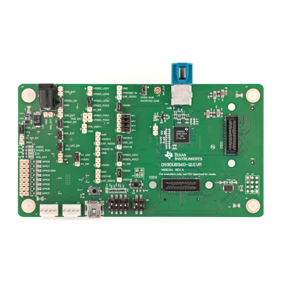
Page 3: Figure 1-1. Ds90Ub960-Q1Evm
MIPI CSI-2 compliant output for interconnect to a downstream processor. The DS90UB960-Q1EVM is configured for communication with up to four DS90UB953-Q1 serializers. It features a quad mini-FAKRA connector, a Quad Mini-Fakra to 4x Single FAKRA cable assembly, and configurable power-over-coax voltage for connecting up to four camera modules (not included). -
Page 4: Application Diagram
Features www.ti.com 2 Features The major components of the DS90UB960-Q1EVM are: • DS90UB960-Q1 – Aggregates data from up to 4 cameras over FPD-Link III interface – Supports 2-Megapixel sensors with HD 1080p resolution at 30/60Hz frame rate (when paired w/ DS90UB953-Q1) –... -
Page 5: Major Components
4. USB2ANY connector for interfacing the EVM to a PC 5. Connectors for accessing DS90UB960-Q1 I2C Ports 6. Connectors for accessing DS90UB960-Q1 GPIOs 7. Barrel jack type connector for powering the DS90UB960-Q1EVM from a single 12V/1A supply 8. Connectors for selecting PoC voltage source FPD-LINK III I/O... -
Page 6: Quick Start Guide
5 Quick Start Guide 1. Ensure all jumpers and switches are placed and configured as shown in Figure 5-1 Figure 5-1. DS90UB960-Q1EVM Jumper and Switch Configuration 2. Connect mini USB J37 to USB port for register programming 3. Optional: Connect an external I... -
Page 7: Board Connections
Alternative to Main Power 6.2 Power Over Coax Interface The DS90UB960-Q1EVM offers four Power-over-Coax interfaces (PoC) to connect cameras through a coaxial cable with FAKRA connectors. Power is delivered on the same conductor that is used to transmit video and control channel between the host and the camera. - Page 8 RIN+ 100 nF RIN- 49.9 : 47 nF Figure 6-2. Power-over-Coax Network Compatible with DS90UB913A-Q1, DS90UB933-Q1, DS90UB935- Q1, and DS90UB953-Q1 DS90UB960-Q1EVM User's Guide SNLU226B – FEBRUARY 2018 – REVISED APRIL 2021 Submit Document Feedback Copyright © 2021 Texas Instruments Incorporated...
-
Page 9: Mipi Csi-2 Output Signals
Short J11.7 & J12.4: VFEED_POC2 6.3 MIPI CSI-2 Output Signals Provided on the DS90UB960-Q1EVM, J1 and J3 are Samtec QSH-type connectors that can be mated with a matching QTH type connector on the top. This Samtec connector provides a means to route CSI-2 signals out of the DS90UB960-Q1. -
Page 10: Table 6-4. Mipi Csi-2 (Tx Port 0) Output Signals - J1 Pinout
Signal Name Pin # Signal Name EXT_SCL1 (I2C_SCL or I2C_SCL2) EXT_SDA1 (I2C_SDA or I2C_SDA2) CSI1_CLK_P CSI1_CLK_N EXP_REF_CLK1 CSI1_D0_P (REFCLK) CSI1_D0_N DS90UB960-Q1EVM User's Guide SNLU226B – FEBRUARY 2018 – REVISED APRIL 2021 Submit Document Feedback Copyright © 2021 Texas Instruments Incorporated... -
Page 11: Table 6-6. Mipi Csi-2 Output Signals - J2 Pinout
SPI_MOSI_0 CSI0_D2_P (GPIO0 or GPIO3) SPI_SCLK_0 CSI0_D2_N (GPIO1 or GPIO4) SPI_CSn_0 CSI0_D3_P (GPIO2 or GPIO5) CSI0_D3_N CSI1_CLK_P CSI1_CLK_N CSI1_D0_P VDD_3V3 SNLU226B – FEBRUARY 2018 – REVISED APRIL 2021 DS90UB960-Q1EVM User's Guide Submit Document Feedback Copyright © 2021 Texas Instruments Incorporated... -
Page 12: Fpd-Link Iii Signals
C Interface A standalone external I C host can connect throughJ9, J10 for programming purposes. Examples of external I host controllers are Texas Instruments USB2ANY and Total Phase Aardvark I C/SPI host adapter (Total Phase Part#: TP240141). Optional access to I C signals are also available throughCSI-2 connectors J1, J2, or J3. -
Page 13: Control Interface
LED Name Description GPIO0 Illuminates if GPIO0 is ON GPIO1 Illuminates if GPIO1 is ON GPIO2 Illuminates if GPIO2 is ON SNLU226B – FEBRUARY 2018 – REVISED APRIL 2021 DS90UB960-Q1EVM User's Guide Submit Document Feedback Copyright © 2021 Texas Instruments Incorporated... -
Page 14: Enable And Reset
External control option: A push-button (S2) or SW1 position 2 is available for the manual control of the PBD signal. DS90UB960-Q1EVM User's Guide SNLU226B – FEBRUARY 2018 – REVISED APRIL 2021 Submit Document Feedback Copyright © 2021 Texas Instruments Incorporated... -
Page 15: Alp Software Setup
Analog LaunchPAD” is checked, but it will not be useful until the USB driver is installed and board is attached. Power the DS90UB960-Q1 EVM board with a 12 VDC power supply. SNLU226B – FEBRUARY 2018 – REVISED APRIL 2021 DS90UB960-Q1EVM User's Guide Submit Document Feedback Copyright © 2021 Texas Instruments Incorporated... -
Page 16: Startup - Software Description
Make sure all the software has been installed and the hardware is powered on and connected to the PC. Execute “Analog LaunchPAD” shortcut from the start menu. The default start menu location is under All Programs > Texas Instruments > Analog LaunchPAD vx.x.x > Analog LaunchPAD to start MainGUI.exe. Figure 8-1. Launching ALP... -
Page 17: Information Tab
DS90UB953-Q1 are connected to the EVM. Figure 8-3. Follow-up Screen 8.5 Information Tab The Information tab is shown below. Figure 8-4. ALP Information Tab SNLU226B – FEBRUARY 2018 – REVISED APRIL 2021 DS90UB960-Q1EVM User's Guide Submit Document Feedback Copyright © 2021 Texas Instruments Incorporated... -
Page 18: Registers Tab
8-6. Note that the “Value:” box, , will now show the hex value of that register. Figure 8-6. ALP Device ID Selected DS90UB960-Q1EVM User's Guide SNLU226B – FEBRUARY 2018 – REVISED APRIL 2021 Submit Document Feedback Copyright © 2021 Texas Instruments Incorporated... -
Page 19: Registers Tab - Address 0X00 Expanded
(indicating a “0”). Click the “Apply” button to write to the register, and “refresh” to see the new value of the selected (highlighted) register. The box toggles on every mouse click. SNLU226B – FEBRUARY 2018 – REVISED APRIL 2021 DS90UB960-Q1EVM User's Guide Submit Document Feedback Copyright © 2021 Texas Instruments Incorporated... -
Page 20: Scripting Tab
"configure GPIO3 to bring out Lock for Port3" board.WriteReg(0x13,0x8D) time.sleep(0.1) print "CSI_PORT_SEL" board.WriteReg(0x32,0x01) # CSI0 select time.sleep(0.1) print "CSI_PLL_CTL" DS90UB960-Q1EVM User's Guide SNLU226B – FEBRUARY 2018 – REVISED APRIL 2021 Submit Document Feedback Copyright © 2021 Texas Instruments Incorporated... - Page 21 # forwarding of RX 2 to CSI0 time.sleep(0.1) print "FPD3_PORT_SEL" board.WriteReg(0x4c,0x24) # RX_PORT2 time.sleep(0.1) print "enable pass throu" board.WriteReg(0x58,0x58) # enable pass throu time.sleep(0.1) SNLU226B – FEBRUARY 2018 – REVISED APRIL 2021 DS90UB960-Q1EVM User's Guide Submit Document Feedback Copyright © 2021 Texas Instruments Incorporated...
- Page 22 # print "SlaveID[0] 0x5d value ", hex(board.ReadReg(0x5d)) time.sleep(0.1) board.WriteReg(0x65,0x68) # print "SlaveAlias[0] 0x65 value ", hex(board.ReadReg(0x65)) time.sleep(0.1) ######################################################### DS90UB960-Q1EVM User's Guide SNLU226B – FEBRUARY 2018 – REVISED APRIL 2021 Submit Document Feedback Copyright © 2021 Texas Instruments Incorporated...
-
Page 23: Troubleshooting Alp Software
Find the correct profile under the Select a Daughter Board list, highlight the profile and press Add. If DS90UB960 ALP profile is not listed, contact your TI representative to obtain it. The ALP profiles are typically located in the ALP installation directory such as "C:\Program Files (x86)\Texas Instruments\Analog LaunchPAD v1.56.0010\Profiles\". - Page 24 Figure 9-3. Add Correct Profile Select Ok and the correct profile must now be loaded. Figure 9-4. Finish Setup DS90UB960-Q1EVM User's Guide SNLU226B – FEBRUARY 2018 – REVISED APRIL 2021 Submit Document Feedback Copyright © 2021 Texas Instruments Incorporated...
-
Page 25: Alp Does Not Detect The Evm
When the ALP is operating in demo mode there is a “(Demo Mode)” indication in the lower left of the application status bar as shown below. SNLU226B – FEBRUARY 2018 – REVISED APRIL 2021 DS90UB960-Q1EVM User's Guide Submit Document Feedback Copyright © 2021 Texas Instruments Incorporated... - Page 26 For additional information about using ALP software with FPD-Link III device, review the following training material: Use of Analog Launch Pad (ALP) GUI to configure the FPD-Link EVMs DS90UB960-Q1EVM User's Guide SNLU226B – FEBRUARY 2018 – REVISED APRIL 2021 Submit Document Feedback Copyright © 2021 Texas Instruments Incorporated...
-
Page 27: Typical Connection And Test Equipment
MIPI CSI-2 Contents of Demo Kit FPD-Link III + PoC Logic Analyzer / Oscilloscope Figure 12-2. Typical Test Setup for Evaluation SNLU226B – FEBRUARY 2018 – REVISED APRIL 2021 DS90UB960-Q1EVM User's Guide Submit Document Feedback Copyright © 2021 Texas Instruments Incorporated... -
Page 28: Equipment References
Aardvark I C/SPI Host Adapter Part Number: TP240141 www.totalphase.com/products/aardvark_i2cspi 14 Cable References FAKRA coaxial cable: www.leoni-automotive-cables.com Rosenberger FAKRA connector: http://www.rosenberger.com/en/products/automotive/fakra.php DS90UB960-Q1EVM User's Guide SNLU226B – FEBRUARY 2018 – REVISED APRIL 2021 Submit Document Feedback Copyright © 2021 Texas Instruments Incorporated... -
Page 29: Bill Of Materials
Bill of Materials 15 Bill of Materials Table 15-1. BOM for DS90UB960-Q1EVM Item Quantity Designator Part Number Manufacturer Description !PCB1 HSDC011 Printed Circuit Board C1, C2, C3, C4 08051C472KAT2A CAP, CERM, 4700 pF, 100 V, +/- 10%, X7R, 0805... - Page 30 Bill of Materials www.ti.com Table 15-1. BOM for DS90UB960-Q1EVM (continued) Item Quantity Designator Part Number Manufacturer Description T495D107M016ATE1 Kemet CAP, TA, 100uF, 16V, +/-20%, 0.1 ohm, GRM32ER61C476ME MuRata CAP, CERM, 47uF, 16V, +/-20%, X5R, 1210 GRM155R71H332KA MuRata CAP, CERM, 3300pF,...
- Page 31 Bill of Materials Table 15-1. BOM for DS90UB960-Q1EVM (continued) Item Quantity Designator Part Number Manufacturer Description H5, H6, H7, H8 1902E Keystone Standoff, Hex, 1"L #4-40 Nylon LM4-308-0300-Z- Rosenberger Cable Assembly ZZZZ BMI-S-201-F Laird-Signal Integrity EMI SHIELD, 13.66 x Products 12.70 mm, SMT...
- Page 32 Bill of Materials www.ti.com Table 15-1. BOM for DS90UB960-Q1EVM (continued) Item Quantity Designator Part Number Manufacturer Description R3, R5, R10, R14, ERJ-2GE0R00X Panasonic RES, 0, 5%, 0.063 W, R59, R61, R64, R85, 0402 R86, R87, R88, R124, R132, R141, R151...
- Page 33 Bill of Materials Table 15-1. BOM for DS90UB960-Q1EVM (continued) Item Quantity Designator Part Number Manufacturer Description R136, R137 CRCW04022K40JNE Vishay-Dale RES, 2.4 k, 5%, 0.063 W, 0402 R143, R144 CRCW040233R0JNE Vishay-Dale RES, 33 ohm, 5%, 0.063W, 0402 R145 CRCW04021K50JNE Vishay-Dale RES, 1.5k ohm, 5%,...
- Page 34 Bill of Materials www.ti.com Table 15-1. BOM for DS90UB960-Q1EVM (continued) Item Quantity Designator Part Number Manufacturer Description TPS73533DRBR Texas Instruments 500mA, Low Quiescent Current, Ultra-Low Noise, High PSRR Low-Dropout Linear Regulator, DRB0008A TPD4E004DRYR Texas Instruments ESD-Protection Array for High-Speed Data Interfaces, 4...
- Page 35 Bill of Materials Table 15-1. BOM for DS90UB960-Q1EVM (continued) Item Quantity Designator Part Number Manufacturer Description R34, R41 CRCW06030000Z0E Vishay-Dale RES, 0 ohm, 5%, 0.1W, 0603 504L50R0FTNCFT AT Ceramics RES, 50, 1%, 0.125 W, AEC-Q200 Grade 1, 0402 R130...
-
Page 36: Pcb Schematics
I2C Conne ctor S tra p Re s is tors / J umpe rs US B2ANY US B Copyright © 2018, Texas Instruments Incorporated DS90UB960-Q1EVM User's Guide SNLU226B – FEBRUARY 2018 – REVISED APRIL 2021 Submit Document Feedback Copyright © 2021 Texas Instruments Incorporated... - Page 37 I2C_S DA I2C_S DA2 I2C_S DA I2C_S DA2 MODE S W1B 4.7pF 4.7pF 4.7pF 4.7pF Copyright © 2018, Texas Instruments Incorporated SNLU226B – FEBRUARY 2018 – REVISED APRIL 2021 DS90UB960-Q1EVM User's Guide Submit Document Feedback Copyright © 2021 Texas Instruments Incorporated...
- Page 38 GP IO7 MP 1 MP 2 MP 3 MP 4 Gre e n TOP MOUNT Copyright © 2018, Texas Instruments Incorporated DS90UB960-Q1EVM User's Guide SNLU226B – FEBRUARY 2018 – REVISED APRIL 2021 Submit Document Feedback Copyright © 2021 Texas Instruments Incorporated...
- Page 39 CN3RIN2_N RIN2_N CN4RIN3_N RIN3_N RIN2_N RIN3_N 49.9 49.9 0.015µF 0.015µF CN1RIN0_P CN2RIN1_P CN3RIN2_P CN4RIN3_P Copyright © 2018, Texas Instruments Incorporated SNLU226B – FEBRUARY 2018 – REVISED APRIL 2021 DS90UB960-Q1EVM User's Guide Submit Document Feedback Copyright © 2021 Texas Instruments Incorporated...
- Page 40 VDD_I2C VDD33 TPS767D318PWP 4.7µF C116 0.1µF C117 VDD3V3 EXT_VDD3V3 10µF 0.1µF VDD3V3 VDD_I2C VDD1V8 Copyright © 2018, Texas Instruments Incorporated DS90UB960-Q1EVM User's Guide SNLU226B – FEBRUARY 2018 – REVISED APRIL 2021 Submit Document Feedback Copyright © 2021 Texas Instruments Incorporated...
- Page 41 DVS S 2 I2C_S DA GP IO0/I2C(S DA) 2200pF MSP430F5529IPN C132 C133 0.1µF 0.1µF Copyright © 2018, Texas Instruments Incorporated SNLU226B – FEBRUARY 2018 – REVISED APRIL 2021 DS90UB960-Q1EVM User's Guide Submit Document Feedback Copyright © 2021 Texas Instruments Incorporated...
- Page 42 ZZ17 As se mbly Note S H-J 14 P la ce S hunt S H-J 14 on J27. 1-2 Copyright © 2018, Texas Instruments Incorporated DS90UB960-Q1EVM User's Guide SNLU226B – FEBRUARY 2018 – REVISED APRIL 2021 Submit Document Feedback Copyright © 2021 Texas Instruments Incorporated...
-
Page 43: Board Layout
PCB Schematics 17 Board Layout Figure 17-1. Top View Composite Figure 17-2. Layer 1: Top Signal Layer SNLU226B – FEBRUARY 2018 – REVISED APRIL 2021 DS90UB960-Q1EVM User's Guide Submit Document Feedback Copyright © 2021 Texas Instruments Incorporated... - Page 44 PCB Schematics www.ti.com Figure 17-3. Layer 2: GND 1 Layer Figure 17-4. Layer 3: Inner Signal 1 Layer DS90UB960-Q1EVM User's Guide SNLU226B – FEBRUARY 2018 – REVISED APRIL 2021 Submit Document Feedback Copyright © 2021 Texas Instruments Incorporated...
- Page 45 PCB Schematics Figure 17-5. Layer 4: GND 2 Layer Figure 17-6. Layer 5: GND 3 Layer SNLU226B – FEBRUARY 2018 – REVISED APRIL 2021 DS90UB960-Q1EVM User's Guide Submit Document Feedback Copyright © 2021 Texas Instruments Incorporated...
- Page 46 PCB Schematics www.ti.com Figure 17-7. Layer 6: Inner Signal 2 Layer Figure 17-8. Layer 7: GND 4 Layer DS90UB960-Q1EVM User's Guide SNLU226B – FEBRUARY 2018 – REVISED APRIL 2021 Submit Document Feedback Copyright © 2021 Texas Instruments Incorporated...
- Page 47 PCB Schematics Figure 17-9. Layer 8: Bottom Signal Layer Figure 17-10. Bottom Overlay SNLU226B – FEBRUARY 2018 – REVISED APRIL 2021 DS90UB960-Q1EVM User's Guide Submit Document Feedback Copyright © 2021 Texas Instruments Incorporated...
-
Page 48: Revision History
Figure 6-2 ............................... • Added Table 6-2 ..............................7 • Updated Bill of Materials...........................29 • Updated PCB Schematics..........................• Updated Board Layout............................43 DS90UB960-Q1EVM User's Guide SNLU226B – FEBRUARY 2018 – REVISED APRIL 2021 Submit Document Feedback Copyright © 2021 Texas Instruments Incorporated... - Page 49 STANDARD TERMS FOR EVALUATION MODULES Delivery: TI delivers TI evaluation boards, kits, or modules, including any accompanying demonstration software, components, and/or documentation which may be provided together or separately (collectively, an “EVM” or “EVMs”) to the User (“User”) in accordance with the terms set forth herein.
- Page 50 www.ti.com Regulatory Notices: 3.1 United States 3.1.1 Notice applicable to EVMs not FCC-Approved: FCC NOTICE: This kit is designed to allow product developers to evaluate electronic components, circuitry, or software associated with the kit to determine whether to incorporate such items in a finished product and software developers to write software applications for use with the end product.
- Page 51 www.ti.com Concernant les EVMs avec antennes détachables Conformément à la réglementation d'Industrie Canada, le présent émetteur radio peut fonctionner avec une antenne d'un type et d'un gain maximal (ou inférieur) approuvé pour l'émetteur par Industrie Canada. Dans le but de réduire les risques de brouillage radioélectrique à...
- Page 52 www.ti.com EVM Use Restrictions and Warnings: 4.1 EVMS ARE NOT FOR USE IN FUNCTIONAL SAFETY AND/OR SAFETY CRITICAL EVALUATIONS, INCLUDING BUT NOT LIMITED TO EVALUATIONS OF LIFE SUPPORT APPLICATIONS. 4.2 User must read and apply the user guide and other available documentation provided by TI regarding the EVM prior to handling or using the EVM, including without limitation any warning or restriction notices.
- Page 53 Notwithstanding the foregoing, any judgment may be enforced in any United States or foreign court, and TI may seek injunctive relief in any United States or foreign court. Mailing Address: Texas Instruments, Post Office Box 655303, Dallas, Texas 75265 Copyright © 2019, Texas Instruments Incorporated...
- Page 54 TI products. TI’s provision of these resources does not expand or otherwise alter TI’s applicable warranties or warranty disclaimers for TI products.IMPORTANT NOTICE Mailing Address: Texas Instruments, Post Office Box 655303, Dallas, Texas 75265 Copyright © 2021, Texas Instruments Incorporated...
Need help?
Do you have a question about the DS90UB960-Q1EVM and is the answer not in the manual?
Questions and answers