Texas Instruments DS90UB954-Q1EVM User Manual
Hide thumbs
Also See for DS90UB954-Q1EVM:
- User manual (67 pages) ,
- User manual (67 pages) ,
- User manual (55 pages)

Related Manuals for Texas Instruments DS90UB954-Q1EVM


Summary of Contents for Texas Instruments DS90UB954-Q1EVM
- Page 1 DS90UB954-Q1EVM User's Guide User's Guide Literature Number: SNLU223 December 2016...
-
Page 2: Table Of Contents
................1.12.1 ALP Loads the Incorrect Profile .................. 1.12.2 ALP does not detect the EVM ......................1.13 Bill of Materials ......................... PCB Schematics ........................Board Layout Contents SNLU223 – December 2016 Submit Documentation Feedback Copyright © 2016, Texas Instruments Incorporated... - Page 3 3-6. Mid Signal Layer 3 ......................3-7. Mid Signal Layer 4 ....................... 3-8. Bottom Signal Layer ....................... 3-9. Bottom solder ......................3-10. Bottom Overlay SNLU223 – December 2016 List of Figures Submit Documentation Feedback Copyright © 2016, Texas Instruments Incorporated...
- Page 4 ....................1-9. CMLOUTP Output Signals ....................... 1-10. Mode SW-DIP4 - S1 ....................1-11. Control SW-DIP2 - SW1 ......................... 1-12. LEDs ....................1-13. DS90UB954EVM BOM List of Tables SNLU223 – December 2016 Submit Documentation Feedback Copyright © 2016, Texas Instruments Incorporated...
-
Page 5: Ds90Ub954-Q1Evm User's Guide
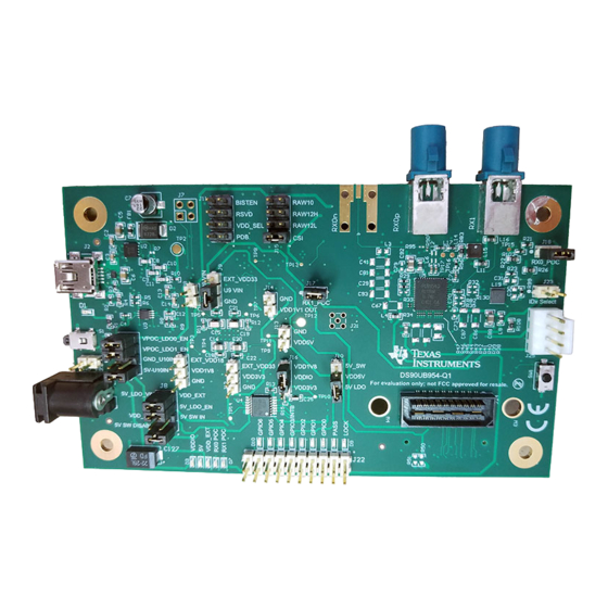
DS90UB954-Q1EVM User's Guide Introduction The Texas Instruments DS90UB954-Q1EVM evaluation module (EVM) is a functional board design for evaluating the DS90UB954-Q1 FPD-Link III deserializer, which converts serialized camera data to MIPI CSI-2 for processing. The MIPI CSI-2 output has four available lanes, and can be configured for either four-lane output or replicated two-lane output. -
Page 6: Quick Start Guide
Quick Start Guide www.ti.com Quick Start Guide 1.3.1 System Requirements The major components of the DS90UB954-Q1EVM are: • DS90UB954-Q1 • On-board Power-over-Coax (POC) interface • Two FAKRA coax connectors for digital video, power, control and diagnostics • Samtec QSH type connector for CSI-2 interface •... -
Page 7: Setup The Ds90Ub954Evm
2. Configure switches S1 and SW1 to set device’s operating modes 3. Configure VFEED power supply for RX0 and RX1 with J32 header 4. Connect the DS90UB954-Q1EVM to DS90UB953EVM using coax cable 5. Interface MIPI CSI-2 output signals (J5) to application processor 6. -
Page 8: Power Over Coax Interface
1.4.3 Power Over Coax Interface The DS90UB954-Q1EVM offers two power over coax interfaces (POC) to connect cameras through a coaxial cable with FAKRA connectors. Power is delivered on the same conductor that is used to transmit video and control channel data between the host and the camera. By default, 5V power supply is applied over the coax cable. -
Page 9: Power Over Coax Network For Use With Ds90Ub933
RX0 or RX1. Power supply is not fused. Over-voltage will cause damage to boards directly connected due to incorrect input power supplies. SNLU223 – December 2016 DS90UB954-Q1EVM User's Guide Submit Documentation Feedback Copyright © 2016, Texas Instruments Incorporated... -
Page 10: Mipi Csi-2 Output Signals
Short J32.3 & J33.2: VFEED_POC2 1.4.4 MIPI CSI-2 Output Signals Provided on the DS90UB954-Q1EVM, J5 and J6 are Samtec QSH-type connectors that can be mated with a matching QTH type connector. This Samtec connector provides a means to route CSI-2 signals out of the DS90UB954-Q1. -
Page 11: Fpd-Link Iii Signals
In addition to the on-board USB2ANY controller accessible via the mini-USB port, a standalone external C host can connect via J4 for programming purposes. Examples of external I C host controllers are Texas Instruments USB2ANY and Total Phase Aardvark I C/SPI host adapter (Total Phase Part#: TP240141). -
Page 12: Control Interface
Power-down Mode Table 1-12. LEDs Reference LED Color LED Name Description Green GPIO0 Illuminates if GPIO0 is HIGH Green GPIO1 Illuminates if GPIO1 is HIGH DS90UB954-Q1EVM User's Guide SNLU223 – December 2016 Submit Documentation Feedback Copyright © 2016, Texas Instruments Incorporated... -
Page 13: Enable And Reset
• External control option: A push-button (S2) or SW1 position 4 is available for the manual control of the PDB signal. SNLU223 – December 2016 DS90UB954-Q1EVM User's Guide Submit Documentation Feedback Copyright © 2016, Texas Instruments Incorporated... -
Page 14: Typical Connection And Test Equipment
DS90UB96X-Q1. Figure 1-6. Typical Test Setup for Application The picture below shows a typical test set up using a video generator and logic analyzer. DS90UB954-Q1EVM User's Guide SNLU223 – December 2016 Submit Documentation Feedback Copyright © 2016, Texas Instruments Incorporated... -
Page 15: Typical Test Setup For Evaluation
Typical Test Setup www.ti.com Figure 1-7. Typical Test Setup for Evaluation SNLU223 – December 2016 DS90UB954-Q1EVM User's Guide Submit Documentation Feedback Copyright © 2016, Texas Instruments Incorporated... -
Page 16: Equipment References
University of New Hampshire InterOperability Laboratory (UNH-IOL) www.iol.unh.edu/services/testing/mipi/fixtures.php Aardvark I C/SPI Host Adapter Part Number: TP240141 www.totalphase.com/products/aardvark_i2cspi 1.10 Cable References FAKRA coaxial cable: www.leoni-automotive-cables.com Rosenberger FAKRA connector: http://www.rosenberger.com/en/products/automotive/fakra.php DS90UB954-Q1EVM User's Guide SNLU223 – December 2016 Submit Documentation Feedback Copyright © 2016, Texas Instruments Incorporated... -
Page 17: Analog Launchpad (Alp) Software Setup
“Launch Analog LaunchPAD” is checked, but it will not be useful until the USB driver is installed and board is attached. Power the DS90UB96X-Q1 EVM board with a 12 VDC power supply. SNLU223 – December 2016 DS90UB954-Q1EVM User's Guide Submit Documentation Feedback Copyright © 2016, Texas Instruments Incorporated... -
Page 18: Startup - Software Description
Make sure all the software has been installed and the hardware is powered on and connected to the PC. Execute “Analog LaunchPAD” shortcut from the start menu. The default start menu location is under All Programs > Texas Instruments > Analog LaunchPAD vx.x.x > Analog LaunchPAD to start MainGUI.exe. Figure 1-8. Launching ALP The application should come up in the state shown in the figure below. -
Page 19: Information Tab
After selecting the DS90UB96X, the following screen shown in Figure 1-10 should appear. Figure 1-10. Follow-up Screen 1.11.5 Information Tab The Information tab is shown below. Figure 1-11. ALP Information Tab SNLU223 – December 2016 DS90UB954-Q1EVM User's Guide Submit Documentation Feedback Copyright © 2016, Texas Instruments Incorporated... -
Page 20: Registers Tab
Analog LaunchPAD (ALP) Software Setup www.ti.com 1.11.6 Registers Tab The Register tab is shown in Figure 1-12. Figure 1-12. ALP Registers Tab DS90UB954-Q1EVM User's Guide SNLU223 – December 2016 Submit Documentation Feedback Copyright © 2016, Texas Instruments Incorporated... -
Page 21: Registers Tab - Address 0X00 Selected
Address 0x00 selected as shown in Figure 1-13. Note that the “Value:” box, , will now show the hex value of that register. Figure 1-13. ALP Device ID Selected SNLU223 – December 2016 DS90UB954-Q1EVM User's Guide Submit Documentation Feedback Copyright © 2016, Texas Instruments Incorporated... -
Page 22: Registers Tab - Address 0X00 Expanded
(indicating a “1”) or unchecking to remove the check mark (indicating a “0”). Click the “Apply” button to write to the register, and “refresh” to see the new value of the selected (highlighted) register. The box toggles on every mouse click. DS90UB954-Q1EVM User's Guide SNLU223 – December 2016 Submit Documentation Feedback Copyright © 2016, Texas Instruments Incorporated... -
Page 23: Scripting Tab
#954A0 Reference Clock Fix import time devAddr = 0x7A print "This is my address: ", hex(board.ReadI2C(devAddr,0x00,1)) # SBPLL CSI Charge-HI board.WriteI2C(devAddr,0xB0,0x1C) board.WriteI2C(devAddr,0xB1,0x15) board.WriteI2C(devAddr,0xB2,0x30) SNLU223 – December 2016 DS90UB954-Q1EVM User's Guide Submit Documentation Feedback Copyright © 2016, Texas Instruments Incorporated... - Page 24 "** SET ALIAS FOR THE SERIALIZER to 0x30" #time.sleep(0.1) ########### RX0 ########## ## REPLICA R SETTING board.WriteI2C(devAddr,0xB0,0x18) # CH0:04, CH1:08, CH2:0C, CH3:10 board.WriteI2C(devAddr,0xB1,0x03) # REPLICA RDAC (STP) DS90UB954-Q1EVM User's Guide SNLU223 – December 2016 Submit Documentation Feedback Copyright © 2016, Texas Instruments Incorporated...
- Page 25 "** Set BC VOD Higher 0x04 to Ensure Robust BC on 953" #print "\n" # board.WriteI2C(devAddr,0x5B,0) # print "** SET ALIAS FOR THE SERIALIZER back to 0x00 to auto load" SNLU223 – December 2016 DS90UB954-Q1EVM User's Guide Submit Documentation Feedback Copyright © 2016, Texas Instruments Incorporated...
-
Page 26: Troubleshooting Alp Software
USB2ANY/Aardvark Setup found under the tools menu. Figure 1-16. USB2ANY Setup Highlight the incorrect profile in the Defined ALP Devices list and press the remove button. DS90UB954-Q1EVM User's Guide SNLU223 – December 2016 Submit Documentation Feedback Copyright © 2016, Texas Instruments Incorporated... -
Page 27: Remove Incorrect Profile
Find the correct profile under the Select a Daughter Board list, highlight the profile and press Add. Figure 1-18. Add Correct Profile Select Ok and the correct profile should now be loaded. SNLU223 – December 2016 DS90UB954-Q1EVM User's Guide Submit Documentation Feedback Copyright © 2016, Texas Instruments Incorporated... -
Page 28: Finish Setup
Troubleshooting ALP Software www.ti.com Figure 1-19. Finish Setup DS90UB954-Q1EVM User's Guide SNLU223 – December 2016 Submit Documentation Feedback Copyright © 2016, Texas Instruments Incorporated... -
Page 29: Alp Does Not Detect The Evm
When the ALP is operating in demo mode there is a “(Demo Mode)” indication in the lower left of the application status bar as shown below. SNLU223 – December 2016 DS90UB954-Q1EVM User's Guide Submit Documentation Feedback Copyright © 2016, Texas Instruments Incorporated... -
Page 30: Alp In Demo Mode
After demo mode is disabled, the ALP software will poll the ALP hardware. The ALP software will update and have only “DS90UB96X” under the “Devices” pull down menu. DS90UB954-Q1EVM User's Guide SNLU223 – December 2016 Submit Documentation Feedback Copyright © 2016, Texas Instruments Incorporated... -
Page 31: Bill Of Materials
CAP, CERM, 10 µF, 25 V, +/- 20%, X5R, 0603 0.015uF CGA2B3X7R1H153K050 CAP, CERM, 0.015 µF, 50 V, +/- 10%, X7R, AEC-Q200 Grade 1, 0402 SNLU223 – December 2016 DS90UB954-Q1EVM User's Guide Submit Documentation Feedback Copyright © 2016, Texas Instruments Incorporated... - Page 32 BK1608HS600-T Taiyo Yuden Ferrite Bead, 60 ohm @ 100 MHz, 0.8 A, 0603 BMI-S-201-F Laird-Signal EMI SHIELD, 13.66 x 12.70 mm, SMT Integrity Products DS90UB954-Q1EVM User's Guide SNLU223 – December 2016 Submit Documentation Feedback Copyright © 2016, Texas Instruments Incorporated...
- Page 33 Brady Thermal Transfer Printable Labels, 0.650 W x 0.200" H - 10 Q1, Q2 BSS138 Fairchild MOSFET, N-CH, 50 V, 0.22 A, SOT-23 Semiconductor SNLU223 – December 2016 DS90UB954-Q1EVM User's Guide Submit Documentation Feedback Copyright © 2016, Texas Instruments Incorporated...
- Page 34 RES, 33 ohm, 5%, 0.063W, 0402 1.5k CRCW04021K50JNED Vishay-Dale RES, 1.5k ohm, 5%, 0.063W, 0402 R72, R82 CRCW040233K0JNED Vishay-Dale RES, 33k ohm, 5%, 0.063W, 0402 DS90UB954-Q1EVM User's Guide SNLU223 – December 2016 Submit Documentation Feedback Copyright © 2016, Texas Instruments Incorporated...
- Page 35 25 MHz Mixed Signal Microcontroller Instruments with 128 KB Flash, 8192 B SRAM and 63 GPIOs, -40 to 85 degC, 80-pin QFP (PN), Green (RoHS & no Sb/Br) SNLU223 – December 2016 DS90UB954-Q1EVM User's Guide Submit Documentation Feedback Copyright © 2016, Texas Instruments Incorporated...
- Page 36 Linear Regulator, DRB0008A 7C-25.000MCB-T XO, 25.000MHz, 2.5V, SMD Corporation ABM3-25.000MHZ-D2W- Abracon Crystal, 25 MHz, 18 pF, SMD Corportation ECS-240-20-5PX-TR ECS Inc. Crystal, 24.000MHz, 20pF, SMD DS90UB954-Q1EVM User's Guide SNLU223 – December 2016 Submit Documentation Feedback Copyright © 2016, Texas Instruments Incorporated...
-
Page 37: Pcb Schematics
Chapter 2 SNLU223 – December 2016 PCB Schematics SNLU223 – December 2016 PCB Schematics Submit Documentation Feedback Copyright © 2016, Texas Instruments Incorporated... - Page 38 PCB Schematics SNLU223 – December 2016 Submit Documentation Feedback Copyright © 2016, Texas Instruments Incorporated...
- Page 39 SNLU223 – December 2016 PCB Schematics Submit Documentation Feedback Copyright © 2016, Texas Instruments Incorporated...
- Page 40 PCB Schematics SNLU223 – December 2016 Submit Documentation Feedback Copyright © 2016, Texas Instruments Incorporated...
- Page 41 SNLU223 – December 2016 PCB Schematics Submit Documentation Feedback Copyright © 2016, Texas Instruments Incorporated...
- Page 42 PCB Schematics SNLU223 – December 2016 Submit Documentation Feedback Copyright © 2016, Texas Instruments Incorporated...
- Page 43 SNLU223 – December 2016 PCB Schematics Submit Documentation Feedback Copyright © 2016, Texas Instruments Incorporated...
-
Page 44: Board Layout
Chapter 3 SNLU223 – December 2016 Board Layout Figure 3-1. Top Overlay Figure 3-2. Top Solder Board Layout SNLU223 – December 2016 Submit Documentation Feedback Copyright © 2016, Texas Instruments Incorporated... -
Page 45: Top Signal Layer
Figure 3-3. Top Signal Layer Figure 3-4. Mid Signal Layer 1 Figure 3-5. Mid Signal Layer 2 SNLU223 – December 2016 Board Layout Submit Documentation Feedback Copyright © 2016, Texas Instruments Incorporated... -
Page 46: Mid Signal Layer 3
Figure 3-6. Mid Signal Layer 3 Figure 3-7. Mid Signal Layer 4 Figure 3-8. Bottom Signal Layer Board Layout SNLU223 – December 2016 Submit Documentation Feedback Copyright © 2016, Texas Instruments Incorporated... -
Page 47: Bottom Solder
Figure 3-9. Bottom solder Figure 3-10. Bottom Overlay SNLU223 – December 2016 Board Layout Submit Documentation Feedback Copyright © 2016, Texas Instruments Incorporated... - Page 48 IMPORTANT NOTICE FOR TI DESIGN INFORMATION AND RESOURCES Texas Instruments Incorporated (‘TI”) technical, application or other design advice, services or information, including, but not limited to, reference designs and materials relating to evaluation modules, (collectively, “TI Resources”) are intended to assist designers who are developing applications that incorporate TI products;...
Need help?
Do you have a question about the DS90UB954-Q1EVM and is the answer not in the manual?
Questions and answers