Table of Contents
Advertisement
Quick Links
www.ti.com
User's Guide
DS90UB95x-Q1EVM Deserializer User's Guide
Liam Keese
The Texas Instruments DS90UB95x-Q1EVM evaluation modules (EVM) are functional board designs for
evaluating the DS90UB95x-Q1 FPD-Link III and TDES954 V
data to MIPI CSI-2 for processing. The MIPI CSI-2 output has four available lanes, and can be configured for
either four-lane output or replicated two-lane output. When paired with a compatible serializer, the deserializers
receive data from imager(s) supporting cameras as well as satellite RADAR. The DS90UB954-Q1 also supports
DS90UB913A/933 serializers.
Some variants are single channel; for these variants ignore references to RX1. Some references are made to
serializer backward compatibility; refer to the product datasheet for serializer compatibility.
The DS90UB954-Q1EVM is configured for communication with DS90UB953-Q1 and TSER953 on channel
0 (RX0), and DS90UB933-Q1 on channel 1 (RX1). The EVM has two Rosenberger FAKRA connectors and
configurable Power-over-Coax (PoC) voltage for connecting the camera modules (not included). FPD-Link III
3
and V
Link interfaces also include a separate low latency bidirectional control channel that conveys control
2
information from an I
C port. General purpose I/O signals, such as those required for camera synchronization
and functional safety features, also make use of this bidirectional control channel to program registers in the
DS90UB954-Q1 and TDES954, as well as the connected serializer and any remote I2C connected devices.
There is an onboard MSP430 which functions as a USB2ANY bridge for interfacing with a PC for evaluation. The
USB2ANY interfaces with the
1
Trademarks..............................................................................................................................................................................4
2
Introduction.............................................................................................................................................................................4
Guide....................................................................................................................................................................5
Requirements........................................................................................................................................................5
Components..................................................................................................................................................5
3.2 Applications Diagram.........................................................................................................................................................
3.3 Major Components of DS90UB95x-Q1EVM......................................................................................................................
3.4 DS90UB95x-Q1EVM Setup...............................................................................................................................................
4.1 Default Configuration.........................................................................................................................................................
4.2 Power Supply.....................................................................................................................................................................
4.3 Power-over-Coax Interface................................................................................................................................................
4.4 MIPI CSI-2 Output Signals.................................................................................................................................................
4.5 FPD-Link III Signals.........................................................................................................................................................
2
C Interface.....................................................................................................................................................................
4.7 Control Interface...............................................................................................................................................................
Reset..................................................................................................................................................................12
DS90UB936-Q1......................................................................................................................................................12
8 Termination Device...............................................................................................................................................................
Setup.................................................................................................................................................................13
References.......................................................................................................................................................14
References................................................................................................................................................................14
12 Software for DS90UB95xQ1-EVM Evaluation - Analog LaunchPAD (ALP) Software Setup........................................
Requirements....................................................................................................................................................15
SNLU223B - AUGUST 2017 - REVISED APRIL 2021
Submit Document Feedback
ABSTRACT
Analog LaunchPAD
GUI tool.
Table of Contents
Components................................................................................................................................5
Configuration............................................................................................................................6
Equipment............................................................................................................................13
Copyright © 2021 Texas Instruments Incorporated
3
Link deserializers, which convert serialized camera
DS90UB95x-Q1EVM Deserializer User's Guide
Table of Contents
5
5
6
6
7
7
8
10
10
11
13
15
1
Advertisement
Table of Contents

Related Manuals for Texas Instruments DS90UB95x-Q1EVM Series


Summary of Contents for Texas Instruments DS90UB95x-Q1EVM Series
-
Page 1: Table Of Contents
DS90UB95x-Q1EVM Deserializer User's Guide Liam Keese ABSTRACT The Texas Instruments DS90UB95x-Q1EVM evaluation modules (EVM) are functional board designs for evaluating the DS90UB95x-Q1 FPD-Link III and TDES954 V Link deserializers, which convert serialized camera data to MIPI CSI-2 for processing. The MIPI CSI-2 output has four available lanes, and can be configured for either four-lane output or replicated two-lane output. - Page 2 Figure 15-2. DS90UB95x-Q1EVM Main Circuit - Page 1......................Figure 15-3. DS90UB95x-Q1EVM CSI-2 Connectors - Page 2....................39 Figure 15-4. DS90UB95x-Q1EVM PoC Circuits - Page 3......................DS90UB95x-Q1EVM Deserializer User's Guide SNLU223B – AUGUST 2017 – REVISED APRIL 2021 Submit Document Feedback Copyright © 2021 Texas Instruments Incorporated...
- Page 3 Table 4-10. FPD-Link III Mode Control- J15..........................11 Table 4-11. Device Mode Control - J11............................Table 4-12. LEDs..................................Table 17-1. DS90UB95x-Q1EVM BOM............................. SNLU223B – AUGUST 2017 – REVISED APRIL 2021 DS90UB95x-Q1EVM Deserializer User's Guide Submit Document Feedback Copyright © 2021 Texas Instruments Incorporated...
-
Page 4: Trademarks
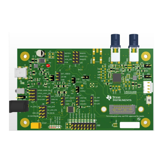
Figure 2-1. DS90UB95x-Q1EVM DS90UB95x-Q1EVM Deserializer User's Guide SNLU223B – AUGUST 2017 – REVISED APRIL 2021 Submit Document Feedback Copyright © 2021 Texas Instruments Incorporated... -
Page 5: Quick Start Guide
DS90UB933 RAW 10/12 Serializer Figure 3-1. Applications Diagram 3.3 Major Components of DS90UB95x-Q1EVM Figure 3-2. Interfacing to the EVM SNLU223B – AUGUST 2017 – REVISED APRIL 2021 DS90UB95x-Q1EVM Deserializer User's Guide Submit Document Feedback Copyright © 2021 Texas Instruments Incorporated... -
Page 6: Ds90Ub95X-Q1Evm Setup
The 3.3V + 1.1V LDO (U10) is powered by VDD5V • The 9V LDO for PoC for RX0 and RX1 are enabled Figure 4-1. DS90UB95x-Q1EVM with Jumpers Highlighted DS90UB95x-Q1EVM Deserializer User's Guide SNLU223B – AUGUST 2017 – REVISED APRIL 2021 Submit Document Feedback Copyright © 2021 Texas Instruments Incorporated... -
Page 7: Power Supply
DS90UB953-Q1EVM (or variant) chipsets. Figure 4-2. Power-over-Coax Network For Use With DS90UB953 SNLU223B – AUGUST 2017 – REVISED APRIL 2021 DS90UB95x-Q1EVM Deserializer User's Guide Submit Document Feedback Copyright © 2021 Texas Instruments Incorporated... -
Page 8: Mipi Csi-2 Output Signals
If the J6 connector on the bottom is to be used, populate the zero ohm resistors on the bottom of the board which extend the traces to the J26 connector. DS90UB95x-Q1EVM Deserializer User's Guide SNLU223B – AUGUST 2017 – REVISED APRIL 2021 Submit Document Feedback Copyright © 2021 Texas Instruments Incorporated... -
Page 9: Table 4-3. Mipi Csi-2 Output Signals - J5 And J6 Pinout
Populate R60-R69, R71,R72 (0Ω resistors) only when using the J26 connector on the bottom of the board. Do not use J24 and J26 connectors at the same time. SNLU223B – AUGUST 2017 – REVISED APRIL 2021 DS90UB95x-Q1EVM Deserializer User's Guide Submit Document Feedback Copyright © 2021 Texas Instruments Incorporated... -
Page 10: Fpd-Link Iii Signals
In addition to the on-board USB2ANY controller accessible via the mini-USB port, a standalone external I C host can connect via J25 for programming purposes. Examples of external I C host controllers are Texas Instruments USB2ANY and Total Phase Aardvark I C/SPI host adapter (Total Phase Part#: TP240141). -
Page 11: Control Interface
VDD 1.1V Source Select 1.8V supply (Default) pins J11.4 Device is powered down Device is enabled (Default) Power-down Mode SNLU223B – AUGUST 2017 – REVISED APRIL 2021 DS90UB95x-Q1EVM Deserializer User's Guide Submit Document Feedback Copyright © 2021 Texas Instruments Incorporated... -
Page 12: Enable And Reset
The DS90UB954-Q1EVM may also be used to evaluate the DS90UB936-Q1. The only modification required is to swap the DS90UB954-Q1 with the DS90UB936-Q1. DS90UB95x-Q1EVM Deserializer User's Guide SNLU223B – AUGUST 2017 – REVISED APRIL 2021 Submit Document Feedback Copyright © 2021 Texas Instruments Incorporated... -
Page 13: Typical Connection And Test Equipment
DS90UB95x-Q1. Figure 9-1. Typical Test Setup for Evaluation SNLU223B – AUGUST 2017 – REVISED APRIL 2021 DS90UB95x-Q1EVM Deserializer User's Guide Submit Document Feedback Copyright © 2021 Texas Instruments Incorporated... -
Page 14: Equipment References
Aardvark I C/SPI Host Adapter Part Number: TP240141 www.totalphase.com/products/aardvark_i2cspi 11 Cable References FAKRA coaxial cable: www.leoni-automotive-cables.com Rosenberger FAKRA connector: http://www.rosenberger.com/en/products/automotive/fakra.php DS90UB95x-Q1EVM Deserializer User's Guide SNLU223B – AUGUST 2017 – REVISED APRIL 2021 Submit Document Feedback Copyright © 2021 Texas Instruments Incorporated... -
Page 15: Software For Ds90Ub95Xq1-Evm Evaluation - Analog Launchpad (Alp) Software Setup
Analog LaunchPAD” is checked, but it will not be useful until the USB driver is installed and board is attached. Power the DS90UB95x-Q1 EVM board with a 12 VDC power supply. SNLU223B – AUGUST 2017 – REVISED APRIL 2021 DS90UB95x-Q1EVM Deserializer User's Guide Submit Document Feedback Copyright © 2021 Texas Instruments Incorporated... -
Page 16: Startup - First Launch
Make sure all the software has been installed and the hardware is powered on and connected to the PC. Execute “Analog LaunchPAD” shortcut from the start menu. The default start menu location is under All Programs > Texas Instruments > Analog LaunchPAD vx.x.x > Analog LaunchPAD to start MainGUI.exe. Figure 12-1. Launching ALP Splash Screen Upon first launch of the Analog LaunchPAD utility, the default device will be DS90UB925. -
Page 17: Figure 12-3. Select Usb2Any/Aardvark Setup To Change Profile
Follow the steps beginning with Figure 12-3 to change the ALP profile to DS90UB95x. Figure 12-3. Select USB2ANY/Aardvark Setup to Change Profile SNLU223B – AUGUST 2017 – REVISED APRIL 2021 DS90UB95x-Q1EVM Deserializer User's Guide Submit Document Feedback Copyright © 2021 Texas Instruments Incorporated... -
Page 18: Figure 12-4. Alp Profiles Dialog
Select the active profile and click "Remove". Scroll down the list of available profiles to DS90UB95x, click to highlight it, click "Add", and click "Ok". Figure 12-4. ALP Profiles Dialog DS90UB95x-Q1EVM Deserializer User's Guide SNLU223B – AUGUST 2017 – REVISED APRIL 2021 Submit Document Feedback Copyright © 2021 Texas Instruments Incorporated... -
Page 19: Figure 12-5. Alp Profiles Dialog (Continued)
Software for DS90UB95xQ1-EVM Evaluation - Analog LaunchPAD (ALP) Software Setup Figure 12-5. ALP Profiles Dialog (continued) SNLU223B – AUGUST 2017 – REVISED APRIL 2021 DS90UB95x-Q1EVM Deserializer User's Guide Submit Document Feedback Copyright © 2021 Texas Instruments Incorporated... -
Page 20: Using Alp And Ds90Ub95X Profile
Information tab. The information tab shown assumes active and locked connection to a DS90UB953 on RX0, and an open port on RX1. Figure 13-1. ALP Information Tab DS90UB95x-Q1EVM Deserializer User's Guide SNLU223B – AUGUST 2017 – REVISED APRIL 2021 Submit Document Feedback Copyright © 2021 Texas Instruments Incorporated... -
Page 21: Registers Tab
"Value: " box at the top. Figure 13-2 shows the register I2C_DEVICE_ID is reading a hexadecimal value of 0x60. Figure 13-2. ALP Registers Tab SNLU223B – AUGUST 2017 – REVISED APRIL 2021 DS90UB95x-Q1EVM Deserializer User's Guide Submit Document Feedback Copyright © 2021 Texas Instruments Incorporated... -
Page 22: Registers Tab - Address 0X00 Expanded
"Save" button, select the file location, and name the file. If desired, comments may be recorded DS90UB95x-Q1EVM Deserializer User's Guide SNLU223B – AUGUST 2017 – REVISED APRIL 2021 Submit Document Feedback Copyright © 2021 Texas Instruments Incorporated... -
Page 23: Figure 13-4. Save Register Settings Step 1
Figure 13-4. Save Register Settings Step 1 Figure 13-5. Save Register Settings Step 2 SNLU223B – AUGUST 2017 – REVISED APRIL 2021 DS90UB95x-Q1EVM Deserializer User's Guide Submit Document Feedback Copyright © 2021 Texas Instruments Incorporated... -
Page 24: Figure 13-6. Save Register Settings Step 3
Using ALP and DS90UB95x Profile www.ti.com Figure 13-6. Save Register Settings Step 3 Figure 13-7. Load Register Settings Step 1 DS90UB95x-Q1EVM Deserializer User's Guide SNLU223B – AUGUST 2017 – REVISED APRIL 2021 Submit Document Feedback Copyright © 2021 Texas Instruments Incorporated... -
Page 25: Figure 13-8. Load Register Settings Step 2
Using ALP and DS90UB95x Profile Figure 13-8. Load Register Settings Step 2 Figure 13-9. Load Register Settings Step 3 SNLU223B – AUGUST 2017 – REVISED APRIL 2021 DS90UB95x-Q1EVM Deserializer User's Guide Submit Document Feedback Copyright © 2021 Texas Instruments Incorporated... -
Page 26: Scripting Tab
Scripting tab or may be run from a .py file using the "Run" button. Example scripts may be found using the "Run PreDef Script" button. Figure 13-10. ALP Scripting Tab DS90UB95x-Q1EVM Deserializer User's Guide SNLU223B – AUGUST 2017 – REVISED APRIL 2021 Submit Document Feedback Copyright © 2021 Texas Instruments Incorporated... -
Page 27: Figure 13-11. Pre-Defined Scripts
"Setup" button, then say "Add", and select the desired name and script. To make the button appear in future instances of ALP, click the "Set As Default" button. Figure 13-12. Custom Button Creation Step 1 SNLU223B – AUGUST 2017 – REVISED APRIL 2021 DS90UB95x-Q1EVM Deserializer User's Guide Submit Document Feedback Copyright © 2021 Texas Instruments Incorporated... -
Page 28: Example Functions
= [I2C Address] Assigns I2C address to be used for board.ReadReg and board.WriteReg commands • Accepts both hex & decimal inputs • Uses the 8-bit form of the I2C address DS90UB95x-Q1EVM Deserializer User's Guide SNLU223B – AUGUST 2017 – REVISED APRIL 2021 Submit Document Feedback Copyright © 2021 Texas Instruments Incorporated... - Page 29 • Ex: board.WriteI2C(0x60, 0x30, [0x01, 0x01]) will set Register 0x3000 of the device with address 0x60 (8-bit form) to have a value of 1 SNLU223B – AUGUST 2017 – REVISED APRIL 2021 DS90UB95x-Q1EVM Deserializer User's Guide Submit Document Feedback Copyright © 2021 Texas Instruments Incorporated...
-
Page 30: Gpio Tab
GPIO tab. This tab may be used to configure the DS90UB95x-Q1 GPIO pins, including the configuration of back channel GPIOs, and FrameSync generation. Figure 13-14. GPIO Tab DS90UB95x-Q1EVM Deserializer User's Guide SNLU223B – AUGUST 2017 – REVISED APRIL 2021 Submit Document Feedback Copyright © 2021 Texas Instruments Incorporated... -
Page 31: Forwarding Tab
Forwarding tab. This tab may be used to configure the forwarding of CSI-2 data. Figure 13-15. Forwarding Tab SNLU223B – AUGUST 2017 – REVISED APRIL 2021 DS90UB95x-Q1EVM Deserializer User's Guide Submit Document Feedback Copyright © 2021 Texas Instruments Incorporated... -
Page 32: Csi Registers Tab
CSI Registers tab. This tab operates in the same way as the Registers tab, but holds the indirect access registers used to configure pattern generation. Figure 13-16. CSI Registers Tab DS90UB95x-Q1EVM Deserializer User's Guide SNLU223B – AUGUST 2017 – REVISED APRIL 2021 Submit Document Feedback Copyright © 2021 Texas Instruments Incorporated... -
Page 33: Remote Registers Tab
The RX Port selection drop-down controls which serializer is communicated with, the serializer connect to Port 0 or the serializer connected to Port 1. Figure 13-17. Remote Registers Tab SNLU223B – AUGUST 2017 – REVISED APRIL 2021 DS90UB95x-Q1EVM Deserializer User's Guide Submit Document Feedback Copyright © 2021 Texas Instruments Incorporated... -
Page 34: Troubleshooting Alp Software
When the ALP is operating in demo mode there is a “(Demo Mode)” indication in the lower left of the application status bar as shown in Figure 14-3. DS90UB95x-Q1EVM Deserializer User's Guide SNLU223B – AUGUST 2017 – REVISED APRIL 2021 Submit Document Feedback Copyright © 2021 Texas Instruments Incorporated... -
Page 35: Usb2Any Firmware Issues
Files (x86)\TI USB2ANY SDK\bin\USB2ANY Firmware Loader.exe" and follow the instructions to flash the latest version of USB2ANY firmware. The firmware loading screen is shown in Figure 14-6. SNLU223B – AUGUST 2017 – REVISED APRIL 2021 DS90UB95x-Q1EVM Deserializer User's Guide Submit Document Feedback Copyright © 2021 Texas Instruments Incorporated... -
Page 36: Figure 14-5. Usb2Any Firmware Update Notice
Troubleshooting ALP Software www.ti.com Figure 14-5. USB2ANY Firmware Update Notice Figure 14-6. USB2ANY Firmware Update Procedure DS90UB95x-Q1EVM Deserializer User's Guide SNLU223B – AUGUST 2017 – REVISED APRIL 2021 Submit Document Feedback Copyright © 2021 Texas Instruments Incorporated... -
Page 37: Ds90Ub95X-Q1Evm Pcb Schematics, Layout And Bill Of Materials - Ds90Ub95X-Q1Evm Schematic
P DB P owe r VDD_S EL S tra p Re s is tors / J umpe rs Copyright © 2017, Texas Instruments Incorporated Figure 15-1. DS90UB95x-Q1EVM Block Diagram SNLU223B – AUGUST 2017 – REVISED APRIL 2021 DS90UB95x-Q1EVM Deserializer User's Guide Submit Document Feedback Copyright ©... -
Page 38: Figure 15-2. Ds90Ub95X-Q1Evm Main Circuit
J34 OPEN: I2C Address = 0x30 (7'b) J34 INSTALLED: I2C Address = 0x3D (7'b) XOUT Copyright © 2017, Texas Instruments Incorporated Figure 15-2. DS90UB95x-Q1EVM Main Circuit - Page 1 DS90UB95x-Q1EVM Deserializer User's Guide SNLU223B – AUGUST 2017 – REVISED APRIL 2021 Submit Document Feedback Copyright ©... -
Page 39: Figure 15-3. Ds90Ub95X-Q1Evm Csi-2 Connectors
MP 1 MP 2 MP 3 MP 4 Bottom Side Connector Copyright © 2017, Texas Instruments Incorporated Figure 15-3. DS90UB95x-Q1EVM CSI-2 Connectors - Page 2 SNLU223B – AUGUST 2017 – REVISED APRIL 2021 DS90UB95x-Q1EVM Deserializer User's Guide Submit Document Feedback... -
Page 40: Figure 15-4. Ds90Ub95X-Q1Evm Poc Circuits
Configure d for ope ra tion with a DS 90UB933-Q1. RIN1_N 49.9 0.047µF Copyright © 2017, Texas Instruments Incorporated Figure 15-4. DS90UB95x-Q1EVM PoC Circuits - Page 3 DS90UB95x-Q1EVM Deserializer User's Guide SNLU223B – AUGUST 2017 – REVISED APRIL 2021 Submit Document Feedback... - Page 41 LM2941 ON/OFF pin is active low, s o is ntall jumper to tie the ON/OFF pin to ground and enable the device . Copyright © 2017, Texas Instruments Incorporated Figure 15-5. DS90UB95x-Q1EVM Power Distribution Circuits - Page 4 SNLU223B – AUGUST 2017 – REVISED APRIL 2021...
- Page 42 GP IO3/INTB GP IO4 GP IO5 GP IO6 EN_25MHz Copyright © 2017, Texas Instruments Incorporated Figure 15-6. DS90UB95x-Q1EVM LED Circuits - Page 5 DS90UB95x-Q1EVM Deserializer User's Guide SNLU223B – AUGUST 2017 – REVISED APRIL 2021 Submit Document Feedback Copyright © 2021 Texas Instruments Incorporated...
- Page 43 2200pF MSP430F5529IPN C111 0.1µF 0.1µF Copyright © 2017, Texas Instruments Incorporated Figure 15-7. DS90UB95x-Q1EVM USB2ANY Circuits - Page 6 SNLU223B – AUGUST 2017 – REVISED APRIL 2021 DS90UB95x-Q1EVM Deserializer User's Guide Submit Document Feedback Copyright © 2021 Texas Instruments Incorporated...
- Page 44 The s e a s se mblie s mus t comply with workma ns hip sta nda rds IP C-A-610 Cla s s 2, unle s s othe rwis e spe cifie d. Copyright © 2017, Texas Instruments Incorporated Figure 15-8. DS90UB95x-Q1EVM Miscellaneous Hardware DS90UB95x-Q1EVM Deserializer User's Guide SNLU223B –...
-
Page 45: Ds90Ub95X-Q1 Evm Pcb Layout
DS90UB95x-Q1EVM PCB Schematics, Layout and Bill of Materials - DS90UB95x-Q1EVM Schematic 16 DS90UB95x-Q1 EVM PCB Layout Figure 16-1. Top View Composite SNLU223B – AUGUST 2017 – REVISED APRIL 2021 DS90UB95x-Q1EVM Deserializer User's Guide Submit Document Feedback Copyright © 2021 Texas Instruments Incorporated... - Page 46 DS90UB95x-Q1EVM PCB Schematics, Layout and Bill of Materials - DS90UB95x-Q1EVM Schematic www.ti.com Figure 16-2. Layer 1: Top Signal Layer DS90UB95x-Q1EVM Deserializer User's Guide SNLU223B – AUGUST 2017 – REVISED APRIL 2021 Submit Document Feedback Copyright © 2021 Texas Instruments Incorporated...
- Page 47 DS90UB95x-Q1EVM PCB Schematics, Layout and Bill of Materials - DS90UB95x-Q1EVM Schematic Figure 16-3. Layer 2: GND Plane 1 SNLU223B – AUGUST 2017 – REVISED APRIL 2021 DS90UB95x-Q1EVM Deserializer User's Guide Submit Document Feedback Copyright © 2021 Texas Instruments Incorporated...
- Page 48 DS90UB95x-Q1EVM PCB Schematics, Layout and Bill of Materials - DS90UB95x-Q1EVM Schematic www.ti.com Figure 16-4. Layer 3: Mid Signal Layer 1 DS90UB95x-Q1EVM Deserializer User's Guide SNLU223B – AUGUST 2017 – REVISED APRIL 2021 Submit Document Feedback Copyright © 2021 Texas Instruments Incorporated...
- Page 49 DS90UB95x-Q1EVM PCB Schematics, Layout and Bill of Materials - DS90UB95x-Q1EVM Schematic Figure 16-5. Layer 4: GND Plane 2 SNLU223B – AUGUST 2017 – REVISED APRIL 2021 DS90UB95x-Q1EVM Deserializer User's Guide Submit Document Feedback Copyright © 2021 Texas Instruments Incorporated...
- Page 50 DS90UB95x-Q1EVM PCB Schematics, Layout and Bill of Materials - DS90UB95x-Q1EVM Schematic www.ti.com Figure 16-6. Layer 5: GND Plane 3 DS90UB95x-Q1EVM Deserializer User's Guide SNLU223B – AUGUST 2017 – REVISED APRIL 2021 Submit Document Feedback Copyright © 2021 Texas Instruments Incorporated...
- Page 51 DS90UB95x-Q1EVM PCB Schematics, Layout and Bill of Materials - DS90UB95x-Q1EVM Schematic Figure 16-7. Layer 6: Mid Signal Layer 2 SNLU223B – AUGUST 2017 – REVISED APRIL 2021 DS90UB95x-Q1EVM Deserializer User's Guide Submit Document Feedback Copyright © 2021 Texas Instruments Incorporated...
- Page 52 DS90UB95x-Q1EVM PCB Schematics, Layout and Bill of Materials - DS90UB95x-Q1EVM Schematic www.ti.com Figure 16-8. Layer 7: GND Plane 4 DS90UB95x-Q1EVM Deserializer User's Guide SNLU223B – AUGUST 2017 – REVISED APRIL 2021 Submit Document Feedback Copyright © 2021 Texas Instruments Incorporated...
- Page 53 DS90UB95x-Q1EVM PCB Schematics, Layout and Bill of Materials - DS90UB95x-Q1EVM Schematic Figure 16-9. Layer 8: Bottom Signal Layer SNLU223B – AUGUST 2017 – REVISED APRIL 2021 DS90UB95x-Q1EVM Deserializer User's Guide Submit Document Feedback Copyright © 2021 Texas Instruments Incorporated...
- Page 54 DS90UB95x-Q1EVM PCB Schematics, Layout and Bill of Materials - DS90UB95x-Q1EVM Schematic www.ti.com Figure 16-10. Bottom View Composite DS90UB95x-Q1EVM Deserializer User's Guide SNLU223B – AUGUST 2017 – REVISED APRIL 2021 Submit Document Feedback Copyright © 2021 Texas Instruments Incorporated...
-
Page 55: Ds90Ub95Xq1-Evm Bill Of Materials
C37, C44, C45, 0.01uF GCM155R71H103KA55D MuRata CAP, CERM, 0.01uF, 50V, +/-10%, C0G/ C60, C64, C65, NP0, 0402 C68, C77, C80 SNLU223B – AUGUST 2017 – REVISED APRIL 2021 DS90UB95x-Q1EVM Deserializer User's Guide Submit Document Feedback Copyright © 2021 Texas Instruments Incorporated... - Page 56 Machine Screw, Round, 4-40 x 1/4, Nylon, Supply Philips panhead PJ-102A CUI Inc. Connector, DC Jack 2.1X5.5 mm, TH DS90UB95x-Q1EVM Deserializer User's Guide SNLU223B – AUGUST 2017 – REVISED APRIL 2021 Submit Document Feedback Copyright © 2021 Texas Instruments Incorporated...
- Page 57 R5, R6, R29, R30, ERJ-2GE0R00X Panasonic RES, 0, 5%, 0.063 W, 0402 R32, R35, R48, R75, R82, R85, R86, R130 SNLU223B – AUGUST 2017 – REVISED APRIL 2021 DS90UB95x-Q1EVM Deserializer User's Guide Submit Document Feedback Copyright © 2021 Texas Instruments Incorporated...
- Page 58 Vishay-Dale RES, 25.5 k, 1%, 0.063 W, 0402 R117 95.3k CRCW040295K3FKED Vishay-Dale RES, 95.3 k, 1%, 0.063 W, 0402 DS90UB95x-Q1EVM Deserializer User's Guide SNLU223B – AUGUST 2017 – REVISED APRIL 2021 Submit Document Feedback Copyright © 2021 Texas Instruments Incorporated...
- Page 59 Crystal, 25 MHz, 18 pF, SMD Corportation SG-210STF25.000000MHZY Epson OSC, 25 MHz, 1.6 to 3.6 V, SMD ECS-240-20-5PX-TR ECS Inc. Crystal, 24.000MHz, 20pF, SMD SNLU223B – AUGUST 2017 – REVISED APRIL 2021 DS90UB95x-Q1EVM Deserializer User's Guide Submit Document Feedback Copyright © 2021 Texas Instruments Incorporated...
-
Page 60: Revision History
Link TDES954..................Changes from Revision * (August 2017) to Revision A (May 2019) Page • Updated User's Guide throughout........................DS90UB95x-Q1EVM Deserializer User's Guide SNLU223B – AUGUST 2017 – REVISED APRIL 2021 Submit Document Feedback Copyright © 2021 Texas Instruments Incorporated... - Page 61 STANDARD TERMS FOR EVALUATION MODULES Delivery: TI delivers TI evaluation boards, kits, or modules, including any accompanying demonstration software, components, and/or documentation which may be provided together or separately (collectively, an “EVM” or “EVMs”) to the User (“User”) in accordance with the terms set forth herein.
- Page 62 www.ti.com Regulatory Notices: 3.1 United States 3.1.1 Notice applicable to EVMs not FCC-Approved: FCC NOTICE: This kit is designed to allow product developers to evaluate electronic components, circuitry, or software associated with the kit to determine whether to incorporate such items in a finished product and software developers to write software applications for use with the end product.
- Page 63 www.ti.com Concernant les EVMs avec antennes détachables Conformément à la réglementation d'Industrie Canada, le présent émetteur radio peut fonctionner avec une antenne d'un type et d'un gain maximal (ou inférieur) approuvé pour l'émetteur par Industrie Canada. Dans le but de réduire les risques de brouillage radioélectrique à...
- Page 64 www.ti.com EVM Use Restrictions and Warnings: 4.1 EVMS ARE NOT FOR USE IN FUNCTIONAL SAFETY AND/OR SAFETY CRITICAL EVALUATIONS, INCLUDING BUT NOT LIMITED TO EVALUATIONS OF LIFE SUPPORT APPLICATIONS. 4.2 User must read and apply the user guide and other available documentation provided by TI regarding the EVM prior to handling or using the EVM, including without limitation any warning or restriction notices.
-
Page 65: Evm
Notwithstanding the foregoing, any judgment may be enforced in any United States or foreign court, and TI may seek injunctive relief in any United States or foreign court. Mailing Address: Texas Instruments, Post Office Box 655303, Dallas, Texas 75265 Copyright © 2019, Texas Instruments Incorporated... - Page 66 TI products. TI’s provision of these resources does not expand or otherwise alter TI’s applicable warranties or warranty disclaimers for TI products.IMPORTANT NOTICE Mailing Address: Texas Instruments, Post Office Box 655303, Dallas, Texas 75265 Copyright © 2021, Texas Instruments Incorporated...
Need help?
Do you have a question about the DS90UB95x-Q1EVM Series and is the answer not in the manual?
Questions and answers