Table of Contents
Advertisement
Quick Links
*15G065104000AK*
P/N: 15G065104000AK V1.0
Quick Installation Guide
EP2C622D16FM / EP2C621D16FM
The server board User's Manual is available for download from the ASRock Rack's official website
at http://www.asrockrack.com.
Take note of the following precautions before you install server board components or change any
server board settings.
1.
Unplug the power cord from the wall socket before touching any components.
2.
To avoid damaging the server board's components due to static electricity, NEVER place your
server board directly on the carpet or the like. Also remember to use a grounded wrist strap or
touch a safety grounded object before you handle the components.
3.
Hold components by the edges and do not touch the ICs.
4.
Whenever you uninstall any component, place it on a grounded anti-static pad or in the bag
that comes with the component.
5.
When placing screws into the screw holes to secure the server board to the chassis, please do
not over-tighten the screws! Doing so may damage the server board.
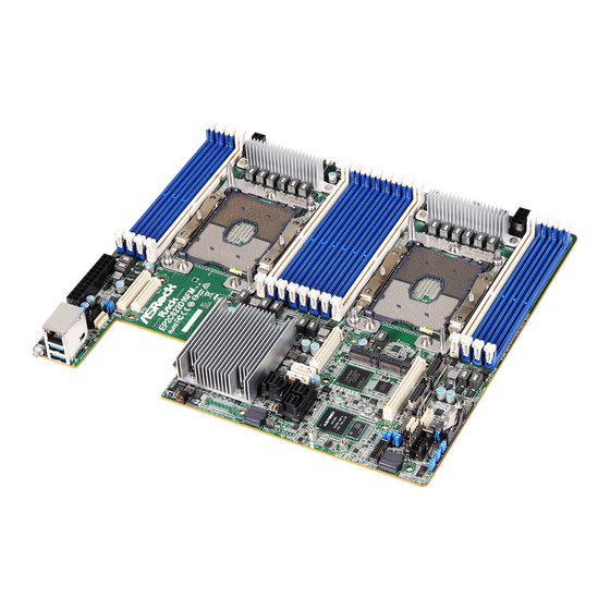
Motherboard Layout
2
1
2
MAIN_PWR
UID1
PWR_PMB
1
1
BPB_SMB
52
51
RoHS
50
MEZZ_A1
NMI1
SYS_LED1
Intel
C622/C621
49
SSATA_2_5
48
BIOS
ROM
47
46
45
CLRMOS1
SATA_0_7
44
43
NUT42
NUT80
BMC
42
NUT42_2
NUT80_2
41
40
MEZZ_A2
39
ME_RECOVERY
VGA
38
1
TPM1
SLIMLIN2
1
1
1
NCSI_SEL1
37
36
NMI_BTN1
1
35
1
AUX_PENEL1
1
IPMB1
34
COM
USB1_2
PLED PWRBTN
33
RAID_1
PENEL1
1
1
1
HDLED RESET
32
BATT(CR2032)
CHASSIS_ID1
CHASSIS_ID2
CHASSIS_ID3
31
30
29
28
27
3
I/O Panel
2
1
3
No. Description
1
UID Switch (UID1)
2
LAN RJ-45 Port (IPMI_LAN)
3
USB 3.0 Ports (USB3_1_2)
3
4
26.7 cm (10.5 in)
DDR4_C1 (64 bit, 288-pin module, Blue)
DDR4_B1 (64 bit, 288-pin module, Blue)
1
FRONT_LED_LAN34
DDR4_A1 (64 bit, 288-pin module, Blue)
DDR4_A2 (64 bit, 288-pin module, White)
MEZZ_B1
MEZZ_C1
CPU1
DDR4_D2 (64 bit, 288-pin module, White)
DDR4_D1 (64 bit, 288-pin module, Blue)
DDR4_E1 (64 bit, 288-pin module, Blue)
DDR4_F1 (64 bit, 288-pin module, Blue)
DDR4_I1 (64 bit, 288-pin module, Blue)
DDR4_H1 (64 bit, 288-pin module, Blue)
DDR4_G1 (64 bit, 288-pin module, Blue)
DDR4_G2 (64 bit, 288-pin module, White)
MEZZ_B2
CPU2
SLIMLIN1
DDR4_J2 (64 bit, 288-pin module
DDR4_J1 (64 bit, 288-pin module
DDR4_K1 (64 bit, 288-pin module
SYS_RST1
DDR4_L1 (64 bit, 288-pin module, Blue)
26
25
24
23
4
5
No. Description
4
NMI Button (NMI1)
5
System Stats LED (SYS_LED1)
1
Install the Server Board
1
Insert the server board into the chassis.
2
A f f i x t he screws clock w ise into t he
mounting holes in all of the corners of
the server board.
Do not over-tighten the screws
CPU1_PWR
CPU1_FAN1
FRNT_FAN1
FRNT_FAN2
CPU2_FAN1
FRNT_FAN3
FRNT_FAN4
CPU2_PWR
, White
)
, Blue
)
, Blue
)
4
Jumper Cap On/Off
When the jumper cap is placed on the pins, the
jumper is "Short". If no jumper cap is placed on the
pins, the jumper is "Open".
The illustration shows a 3-pin jumper whose pin1
and pin2 are "Short" when a jumper cap is placed on
these 2 pins.
www.asrockrack.com
EP2C622D16FM
1
PWR PMBus Header (PWR_PMB1)
2
BPB SMBus Header (BPB_SMB)
3
ATX Power Connector (MAIN_PWR)
4
Front Lan LED Connector (FRONT_LED_LAN34)
5
3 x 288-pin DDR4 DIMM Slots (DDR4_A1, DDR4_B1,
5
DDR4_C1)
6
1 x 288-pin DDR4 DIMM Slot (DDR4_A2)
6
7
CPU1 ATX 12V Power Connector (CPU1_PWR)
7
8
CPU1 Fan Connector (CPU1_FAN1)
9
CPU Socket 1 LGA-3647 (Socket P) (CPU1)
8
10
Front Fan Connector (FRNT_FAN1)
11
Front Fan Connector (FRNT_FAN2)
9
12
1 x 288-pin DDR4 DIMM Slot (DDR4_D2)
3 x 288-pin DDR4 DIMM Slots (DDR4_D1, DDR4_E1,
13
10
DDR4_F1)
3 x 288-pin DDR4 DIMM Slots (DDR4_G1, DDR4_H1,
14
11
DDR4_I1)
15
1 x 288-pin DDR4 DIMM Slot (DDR4_G2)
12
16
CPU2 Fan Connector (CPU2_FAN1)
17
Front Fan Connector (FRNT_FAN3)
13
18
CPU Socket 2 LGA-3647 (Socket P) (CPU2)
19
Front Fan Connector (FRNT_FAN4)
14
20
CPU2 ATX 12V Power Connector (CPU2_PWR)
21
1 x 288-pin DDR4 DIMM Slot (DDR4_J2)
15
3 x 288-pin DDR4 DIMM Slots (DDR4_J1, DDR4_K1,
22
DDR4_L1)
16
23
Slimline NVMe Connector (SLIMLIN1)
24
Slimline NVMe Connector (SLIMLIN2)
25
Intelligent Platform Management Bus header (IPMB_1)
17
18
26
Clear CMOS Pad (SYS_RST1)
27
Virtual RAID On CPU Header (RAID_1)
28
USB 2.0 Header (USB1_2)
19
29
Battery (BATT(CR2032))
30
Chassis ID3 Jumper (CHASSIS_ID3)
20
31
Chassis ID2 Jumper (CHASSIS_ID2)
21
32
Chassis ID1 Jumper (CHASSIS_ID1)
33
System Panel Header (PANEL1)
22
34
COM Port Header (COM)
35
Auxiliary Panel Header (AUX_PANEL1)
36
Non Maskable Interrupt Button (NMI_BTN1)
37
NCSI Mode Jumper (NCSI_SEL1)
38
VGA Header (VGA)
39
ME Recovery Jumper (ME_RECOVERY1)
40
TPM Header (TPM1)
41
Mezzanine Card Slot (MEZZ_A2)
42
M.2 Socket (M2_2) (Type 2242 / 2280)
43
M.2 Socket (M2_1) (Type 2242 / 2280)
44
SATA3 Connector (SSATA_0)
45
Clear CMOS Pad (CLRMOS1)
46
MINI-SAS HD Connector (SATA_0_7)
47
SATA3 Connector (SSATA_1)
48
MINI-SAS HD Connector (SSATA_2_5)
49
Mezzanine Card Slot (MEZZ_B2)
50
Mezzanine Card Slot (MEZZ_A1)
51
Mezzanine Card Slot (MEZZ_C1)
52
Mezzanine Card Slot (MEZZ_B1)
EP2C621D16FM
Advertisement
Table of Contents

Related Manuals for ASROCK Rack EP2C622D16FM


Summary of Contents for ASROCK Rack EP2C622D16FM
- Page 1 EP2C622D16FM EP2C621D16FM Install the Server Board The server board User's Manual is available for download from the ASRock Rack's official website at http://www.asrockrack.com. Take note of the following precautions before you install server board components or change any Insert the server board into the chassis.
- Page 2 Quick Installation Guide EP2C622D16FM / EP2C621D16FM www.asrockrack.com EP2C622D16FM EP2C621D16FM Install the Processor and Heatsink Remove the CPU socket cover. Align and Carefully flip the carrier assembly. Apply Then install the heatsink to the carrier Install the heatsink. Tighten the screws in a sequential order (6-1>6-2>6-3>6-4). When install the processor on the carrier.
Need help?
Do you have a question about the EP2C622D16FM and is the answer not in the manual?
Questions and answers