Table of Contents
Advertisement
Quick Links
*15G065134000AK*
P/N: 15G065134000AK V1.0
Quick Installation Guide
D2143D8UM2 / D2123D8UM2
The server board User's Manual is available for download from the ASRock Rack's offi cial website
at http://www.asrockrack.com.
Take note of the following precautions before you install server board components or change any
server board settings.
1.
Unplug the power cord from the wall socket before touching any components.
2.
To avoid damaging the server board's components due to static electricity, NEVER place your
server board directly on the carpet or the like. Also remember to use a grounded wrist strap or
touch a safety grounded object before you handle the components.
3.
Hold components by the edges and do not touch the ICs.
4.
Whenever you uninstall any component, place it on a grounded anti-static pad or in the bag
that comes with the component.
5.
When placing screws into the screw holes to secure the server board to the chassis, please do
not over-tighten the screws! Doing so may damage the server board.
2
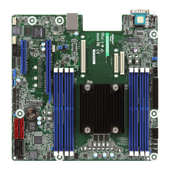
Motherboard Layout
1
2
1
1
ME_RECOVERY1
CHASSIS_ID3
UID1
1
SYSTEM_FAN5
CHASSIS_ID2
1
CHASSIS_ID1
45
44
D2143D8UM2 / D2123D8UM2
RoHS
43
MEZZ_MB_A1
USB 3.0
IPMI
T: USB2
LAN
B: USB1
42
1
NCSI_SEL1
41
1
PECI1
40
1
RAID_1
39
BMC
AST2500
38
PCIE4
37
COM2
BMC_SMB_1
IPMB1
BMC FW
1
1
36
35
34
I/O Panel
3
3
2
1
No. Description
No. Description
1
UID Switch (UID1)
4
2
VGA Port (VGA1)
5
3
COM Port (COM1)
3
4
5
6
7
24.4cm (9.6 in)
1
ATXPWR1
PSU_SMB1
DDR4_B1 (
DDR4,
64 bit, 288-pin module, Blue)
DDR4_B2 (
DDR4,
64 bit, 288-pin module,
DDR4_A1 (
DDR4,
64 bit, 288-pin module, Blue)
DDR4_A2 DDR4,
(
64 bit, 288-pin module,
MEZZ_MB_B1
MEZZ_MB_C1
CPU1
DDR4_C2 (
DDR4,
64 bit, 288-pin module,
DDR4_C1 (
DDR4,
64 bit, 288-pin module,
DDR4_D2 (
DDR4,
64 bit, 288-pin module,
DDR4_D1 DDR4,
(
64 bit, 288-pin module,
PCIE6
M2_80
M2_60
M2_42
M2_30
FRONT_LED_LAN1
SPEAKER1
NMI_BTN1
USB3_3_4
1 1
1 1
1 1
TPM1
AUX_PANEL1
1
1
30
33
32
31
5
4
USB 3.0 Ports (USB3_1_2)
LAN RJ-45 Port (IPMI_LAN)
1
Install the Server Board
1
Insert the server board into the chassis.
2
A f f i x t he screws clock w ise into t he
mounting holes in all of the corners of
the server board.
Do not over-tighten the screws
8
9
10
11
SYSTEM_FAN1
ATX12V1
SYSTEM_FAN3
SYSTEM_FAN2
White
)
White
)
CPU_FAN1
White
)
Blue
)
White
)
Blue
)
Dr.
BIOS
BAT1
Debug
ROM
SSATA_SGPIO1
CLRMOS1
SATA_0_7
SYSTEM_FAN4
SSATA_0
1
T 1
R
1 1
PANEL1
PLED PWRBTN
SATAPWR1
1
1
SSATA_2
HDLED RESET
27
26
25
24
22
29
28
23
21
Jumper Cap On/Off
4
When the jumper cap is placed on the pins, the
jumper is "Short". If no jumper cap is placed on the
pins, the jumper is "Open".
The illustration shows a 3-pin jumper whose pin1
and pin2 are "Short" when a jumper cap is placed on
these 2 pins.
www.asrockrack.com
D2143D8UM2
No. Description
1
System Fan Connector (SYSTEM_FAN5)
2
ME Recovery Jumper (ME_RECOVERY1)
3
Chassis ID Jumper (CHASSIS_ID3)
4
Chassis ID Jumper (CHASSIS_ID2)
5
PSU SMBus (PSU_SMB1)
12
6
Chassis ID Jumper (CHASSIS_ID1)
7
ATX Power Connector (ATXPWR1)
13
8
ATX 12V Power Connector (ATX12V1)
9
System Fan Connector (SYSTEM_FAN3)
10
System Fan Connector (SYSTEM_FAN2)
11
System Fan Connector (SYSTEM_FAN1)
12
2 x 288-pin DDR4 DIMM Slots (DDR4_A1, DDR4_B1)
13
2 x 288-pin DDR4 DIMM Slots (DDR4_A2 DDR4_B2)
14
CPU Fan Connector (CPU_FAN1)
15
2 x 288-pin DDR4 DIMM Slots (DDR4_C2, DDR4_D2)
16
2 x 288-pin DDR4 DIMM Slots (DDR4_C1 DDR4_D1)
14
17
M.2 Socket (M2_1) (Type 2230/2242/2260/2280)
15
18
Clear CMOS Pad (CLRMOS1)
19
SATA SGPIO Connector (SSATA_SGPIO1)
16
20
System Fan Connector (SYSTEM_FAN4)
21
MINI-SAS HD Connector (SATA_0_7)
22
SATA3 Connector (SSATA_0)
17
23
SATA3 Connector (SSATA_2)
18
24
SATA3 Connector (SSATA_1)
19
25
SATA DOM Connector (SSATA_3)
26
SATA DOM Power Jumper (SATAPWR1)
20
27
ermal Sensor Header (TR1)
28
System Panel Header (PANEL1)
29
Non Maskable Interrupt Button (NMI_BTN1)
30
Auxiliary Panel Header (AUX_PANEL1)
31
Front LAN LED Connector (FRONT_LED_LAN1)
32
USB 3.1 Gen1 Header (USB3_3_4)
33
TPM Header (TPM1)
34
COM Port Header (COM2)
35
Intelligent Platform Management Bus header (IPMB1)
36
BMC SMB Header (BMC_SMB_1)
37
PCI Express 3.0 Card Slot 4 (PCIE4)
38
Speaker Header (SPEAKER1)
39
PCI Express 3.0 Card Slot 6 (PCIE6)
40
Virtual RAID On CPU Header (RAID_1)
41
CPU PECI Jumper (PECI1)
42
NCSI Mode Jumper (NCSI_SEL1)
43
Mezzanine Card Slot (MEZZ_MB_A1)
44
Mezzanine Card Slot (MEZZ_MB_C1)
45
Mezzanine Card Slot (MEZZ_MB_B1)
D2123D8UM2
Advertisement
Table of Contents

Related Manuals for ASROCK Rack D2143D8UM2


Summary of Contents for ASROCK Rack D2143D8UM2
- Page 1 D2143D8UM2 D2123D8UM2 Install the Server Board The server board User's Manual is available for download from the ASRock Rack's offi cial website at http://www.asrockrack.com. Take note of the following precautions before you install server board components or change any Insert the server board into the chassis.
- Page 2 Quick Installation Guide D2143D8UM2 / D2123D8UM2 www.asrockrack.com D2143D8UM2 D2123D8UM2 Install the Power Cables LAN Port LED Indications IPMI LAN Port Activity / Link LED Speed LED Status Description Status Description ACT/LINK LED SPEED LED Off No Link Off 10M bps connection or no...
Need help?
Do you have a question about the D2143D8UM2 and is the answer not in the manual?
Questions and answers