Advertisement
Quick Links
*15G065263000AK*
P/N: 15G065263000AK V1.0
Quick Installation Guide
SPC741D8UD-2T | SPC741D8UD-2T/X550
The server board User's Manual is available for download from the ASRock Rack's official website
at http://www.asrockrack.com.
Take note of the following precautions before you install server board components or change any
server board settings.
1.
Unplug the power cord from the wall socket before touching any components.
2.
To avoid damaging the server board's components due to static electricity, NEVER place your
server board directly on the carpet or the like. Also remember to use a grounded wrist strap or
touch a safety grounded object before you handle the components.
3.
Hold components by the edges and do not touch the ICs.
4.
Whenever you uninstall any component, place it on a grounded anti-static pad or in the bag
that comes with the component.
5.
When placing screws into the screw holes to secure the server board to the chassis, please do
not over-tighten the screws! Doing so may damage the server board.
2
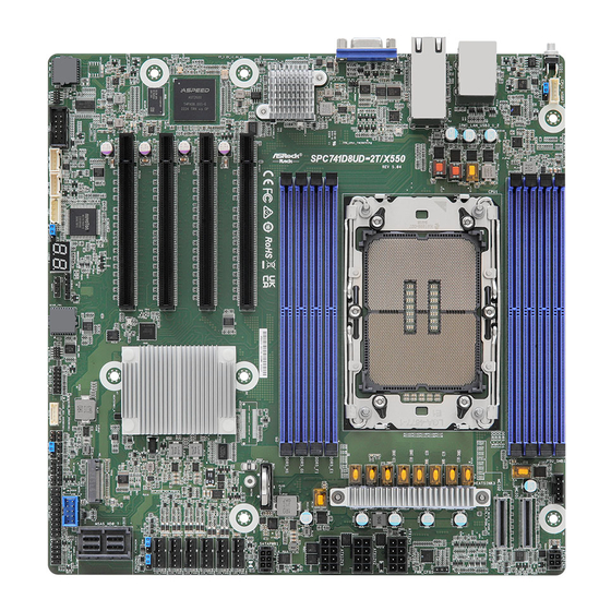
Motherboard Layout
1
2
3
4
DDR5_D1
CPU1_HSBP1
DDR5_C1
UID1
PECI1
DDR5_B1
DDR5_A1
USB 3.2
Gen1 Ports
IPMI_LAN1
T:USB3_2
B:USB3_1
LAN1
LAN2
VGA1
DDR5_E1
DDR5_F1
SPC741D8UD-2T:
DDR5_G1
Intel
X710-AT2
SPC741D8UD-2T/X550:
DDR5_H1
Intel
X550-AT2
PCIE7
45
44
PCIE6
ASPEED
AST2600
PCIE5
43
PCIE4
42
SPC741D8UD-2T/X550 only:
COM1
BMC_SMB_1
BMC
ROM
41
40
3
I/O Panel
3
5
1
2
4
No. Description
1
UID Switch (UID1)
2
USB 3.2 Gen1 Ports (USB3_1_2)
3
LAN RJ-45 Port (IPMI_LAN1)
26.7 cm (10.5 in)
CPU0
SUPER
I/O
BMC_SMB_2
IPMB_1
ME_RECOVERY1
BIOS
ROM
Dr. Debug
39
38
37
6
No. Description
4
10G LAN RJ-45 Port (LAN1)
5
10G LAN RJ-45 Port (LAN2)
6
VGA Port (VGA1)
1
Install the Server Board
1
Insert the server board into the chassis.
2
A f f i x t he screws clock w ise into t he
mounting holes in all of the corners of
the server board.
Do not over-tighten the screws
5
PSU_SMB1
MCIO1
MCIO2
BAT1
M2_1
M2_1
USB1_2
TPM_BIOS_PH1
RAID_1
PASSWORD_CLEAR1
SPEAKER1
AUX_PANEL1
TR1
36
35
34
33
32
31
30
4
Jumper Settings
When the jumper cap is placed on the pins, the jumper
is "Short". If no jumper cap is placed on the pins, the
jumper is "Open".
The illustration shows a 3-pin jumper whose pin1 and
pin2 are "Short" when a jumper cap is placed on these 2
pins.
www.asrockrack.com
No.
Description
Backplane PCI Express Hot-Plug Con-
1
nector (CPU1_HSBP1)
2
CPU PECI Mode Jumper (PECI1)
2 x 288-pin DDR5 DIMM Slots
6
3
(DDR5_A1, DDR5_C1)
ATX4PIN1
2 x 288-pin DDR5 DIMM Slots
7
4
(DDR5_B1, DDR5_D1)
8
5
PSU SMBus Header (PSU_SMB1)
Micro-Fit ATX 4Pin Power Connector
6
(ATX4PIN1)
Mini Cool Edge IO x8 Connector
7
(MCIO1)
9
PWM_CFG1
Mini Cool Edge IO x8 Connector
8
(MCIO2)
10
PWM Configuration Header
ATX12V1
9
11
(PWM_CFG1)
10
LGA 4677 CPU Socket (CPU0)
ATX12V2
11
ATX 12V Power Connector (ATX12V1)
12
12
ATX 12V Power Connector (ATX12V2)
ATX12V3
13
ATX 12V Power Connector (ATX12V3)
13
2 x 288-pin DDR5 DIMM Slots
14
14
(DDR5_E1, DDR5_G1)
15
2 x 288-pin DDR5 DIMM Slots
15
(DDR5_F1, DDR5_H1)
SATAPWR1
Micro-Fit SATA Power Connector
16
16
(SATAPWR1)
17
CLRMOS1
17
Clear CMOS Pad (CLRMOS1)
18
FAN1
18
System Fan Connector (FAN1)
19
FAN2
19
System Fan Connector (FAN2)
20
FAN3
20
System Fan Connector (FAN3)
21
FAN4
21
System Fan Connector (FAN4)
22
FAN5
23
22
System Fan Connector (FAN5)
FAN6
24
23
System Fan Connector (FAN6)
25
MiniSAS HD SATA/PCIE Selection
MINISAS_1 MINISAS_2
24
Jumper (MINISAS_2)
MiniSAS HD SATA/PCIE Selection
26
25
Jumper (MINISAS_1)
27
26
MiniSAS HD Connector (MSAS_HD0_7)
28
27
Speaker Header (SPEAKER1)
SPC741D8UD-2T/X550 only:
USB 2.0 Header (USB1_2)
PANEL1
28
(SPC741D8UD-2T/X550 only)
29
System Panel Header (PANEL1)
30
Auxiliary Panel Header (AUX_PANEL1)
29
Non Maskable Interrupt Button
31
(NMI_BTN1)
32
Thermal Sensor Header (TR1)
Password Reset Jumper
33
(PASSWORD_CLEAR1)
34
Virtual RAID On CPU Header (RAID_1)
35
SPI TPM Header (TPM_BIOS_PH1)
36
M-key M.2 Socket (M2_1) (Type 2280)
ME Recovery Jumper
37
(ME_RECOVERY1)
Intelligent Platform Management Bus
38
Header (IPMB_1)
BMC SMBus Header (BMC_SMB_2)
39
(SPC741D8UD-2T/X550 only)
40
BMC SMBus Header (BMC_SMB_1)
41
Serial Port Header (COM1)
42
PCI Express 5.0 x16 Slot (PCIE4)
43
PCI Express 5.0 x16 Slot (PCIE5)
44
PCI Express 5.0 x16 Slot (PCIE6)
45
PCI Express 5.0 x16 Slot (PCIE7)
SPC741D8UD-2T
SPC741D8UD-2T/X550
Advertisement

Related Manuals for ASROCK Rack SPC741D8UD-2T


Summary of Contents for ASROCK Rack SPC741D8UD-2T
- Page 1 SPC741D8UD-2T SPC741D8UD-2T/X550 Install the Server Board The server board User's Manual is available for download from the ASRock Rack's official website at http://www.asrockrack.com. Take note of the following precautions before you install server board components or change any Insert the server board into the chassis.
- Page 2 Quick Installation Guide SPC741D8UD-2T | SPC741D8UD-2T/X550 www.asrockrack.com SPC741D8UD-2T SPC741D8UD-2T/X550 Install the Processor and Heatsink Remove the CPU socket cover and open Align and install the processor on the Carefully flip the carrier assembly. Apply Install the heatsink to the CPU carrier.
Need help?
Do you have a question about the SPC741D8UD-2T and is the answer not in the manual?
Questions and answers