Table of Contents
Advertisement
Quick Links
*15G065100000AK*
P/N: 15G065100000AK V1.0
Quick Installation Guide
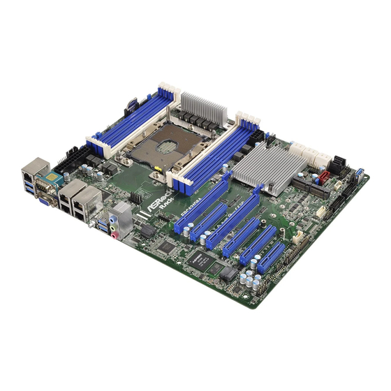
EPC621D8A
The server board User's Manual is available for download from the ASRock Rack's official website
at http://www.asrockrack.com.
Take note of the following precautions before you install server board components or change any
server board settings.
1.
Unplug the power cord from the wall socket before touching any components.
2.
To avoid damaging the server board's components due to static electricity, NEVER place your
server board directly on the carpet or the like. Also remember to use a grounded wrist strap or
touch a safety grounded object before you handle the components.
3.
Hold components by the edges and do not touch the ICs.
4.
Whenever you uninstall any component, place it on a grounded anti-static pad or in the bag
that comes with the component.
5.
When placing screws into the screw holes to secure the server board to the chassis, please do
not over-tighten the screws! Doing so may damage the server board.
2
Motherboard Layout
1
REAR_FAN1
ATXPWR1
46
LAN1 LAN2
LAN3 LAN4
45
UID1
1
FRONT_LED_LAN34
USB 3.0
T: USB3_2
B: USB3_1
44
BIOS
ROM
BMC
PCIE1
HD_AUDIO1
T 1
R
1
1
1
43
42
3
I/O Panel
2
4
6
3
5
1
No. Description
1
LAN RJ-45 Port (IPMI_LAN)
2
USB 3.0 Ports (USB3_1_2)
3
VGA Port (VGA1)
4
Serial Port (COM1)
5
LAN RJ-45 Port (LAN1)
6
LAN RJ-45 Port (LAN2)
7
LAN RJ-45 Port (LAN3)
2
3
4
5
6
7
8 9
10
PSU_SMB1
1
1
1
1
1
CHASSIS_ID0
CHASSIS_ID1
CHASSIS_ID2
NMI_BTN1
1
1
1
1
PECI1
PMBUS_SEL_ALT1
PMBUS_SEL_DAT1
PMBUS_SEL_CLK1
DDR4_C1 (64 bit, 288-pin module)
DDR4_B1 (64 bit, 288-pin module)
DDR4_A1 (64 bit, 288-pin module)
DDR4_A2 (64 bit, 288-pin module)
CPU1
CPU1_FAN1
DDR4_D2 (64 bit, 288-pin module)
DDR4_D1 (64 bit, 288-pin module)
DDR4_E1 (64 bit, 288-pin module)
DDR4_F1 (64 bit, 288-pin module)
EPC621D8A
PCIE6
PCIE5
RoHS
PCIE4
PCIE3
NUT80
NUT60
NUT42
NUT30
PCIE2
NUT80_2
NUT60_2
NUT42_2
NUT30_2
1
1
BMC_SMB_1
SPEAKER
PANEL1
PLED PWRBTN
AUX_PANEL1
TPM1
1
1
1
HDLED RESET
41
40
39
38
37
13
8
12
7
9
10
11
No. Description
8
LAN RJ-45 Port (LAN4)
9
UID Switch (UID1)
10
USB 3.0 Ports (USB3_3_4)
11
Line In (Light Blue)
12
Front Speaker (Lime)
13
Microphone (Pink)
1
Install the Server Board
1
Insert the server board into the chassis.
2
A f f i x t he screws clock w ise into t he
mounting holes in all of the corners of
the server board.
Do not over-tighten the screws
11
12
24.4cm (9.6 in)
FRNT_FAN1
CMOS
1
Battery
AEP_1
ATX12V1
AEP_2
1
FRNT_FAN2
Intel
C621
SSATA_SGPIO1
1
SATAPWR1
SATA_0_3
1
(RED)
SATA_4
SATA_SGPIO1
1
1
SATA_SGPIO2
IPMB_1
FRNT_FAN3
USB3_7_8
USB3_5_6
USB3_9
36
35
34
33
32
4
Jumper Cap On/Off
When the jumper cap is placed on the pins, the
jumper is "Short". If no jumper cap is placed on the
pins, the jumper is "Open".
The illustration shows a 3-pin jumper whose pin1
and pin2 are "Short" when a jumper cap is placed on
these 2 pins.
www.asrockrack.com
No. Description
1
ATX Power Connector (ATXPWR1)
2
Rear Fan Connector (REAR_FAN1)
3
PSU SMBus (PSU_SMB1)
4
CPU PECI Jumper (PECI1)
13
5
PMBUS Mode Jumper (PMBUS_SEL_ALT1)
14
6
Chassis ID0 Jumper (CHASSIS_ID0)
7
Chassis ID1 Jumper (CHASSIS_ID1)
8
Chassis ID2 Jumper (CHASSIS_ID2)
9
PMBUS Mode Jumper (PMBUS_SEL_CLK1)
10
Non Maskable Interrupt Button (NMI_BTN1)
11
Front Fan Connector (FRNT_FAN1)
12
Support NVDIMM Jumer (AEP_1)
3 x 288-pin DDR4 DIMM Slots (DDR4_A1, DDR4_
13
15
B1, DDR4_C1, Blue)
14
1 x 288-pin DDR4 DIMM Slot (DDR4_A2, White)
16
15
1 x 288-pin DDR4 DIMM Slot (DDR4_D2, White)
3 x 288-pin DDR4 DIMM Slots (DDR4_D1, DDR4_
16
17
E1, DDR4_F1, Blue)
18
17
ATX 12V Power Connector (ATX12V1)
19
18
Support NVDIMM Jumer (AEP_2)
20
21
19
Front Fan Connector (FRNT_FAN2)
22
20
SATA SGPIO Connector (SSATA_SGPIO1)
23
21
SATA2 Connector (SSATA_1)
24
22
SATA2 Connector (SSATA_0)
25
23
SATA2 Connector (SSATA_3)
26
24
SATA2 Connector (SSATA_2)
27
25
SATA2 Connector (SSATA_5)
28
26
SATA2 Connector (SSATA_4)
29
30
27
SATA DOM Power Jumper (SATAPWR1)
31
28
MINI-SAS HD Connector (SATA_0_3)
29
SATA SGPIO Connector (SATA_SGPIO1)
30
SATA SGPIO Connector (SATA_SGPIO2)
31
Front Fan Connector (FRNT_FAN3)
32
Vertical Type A USB 3.0 (USB3_9)
33
SATA3 DOM Connector (SATA_4), Red
34
USB 3.0 Header (USB3_5_6)
35
USB 3.0 Header (USB3_7_8)
36
System Panel Header (PANEL1)
37
Intelligent Platform Management Bus header (IPMB_1)
38
BMC SMBus Header (BMC_SMB_1)
39
TPM Header (TPM1)
40
Auxiliary Panel Header (AUX_PANEL1)
41
Speaker Header (SPEAKER1)
42
Thermal Sensor header (TR1)
43
Front Panel Audio Header (HD_AUDIO1)
44
CPU Fan Connector (CPU1_FAN1)
45
Front LAN LED Connector (FRONT_LED_LAN34)
46
PMBUS Mode Jumper (PMBUS_SEL_DAT1)
Advertisement
Table of Contents

Related Manuals for ASROCK Rack EPC621D8A


Summary of Contents for ASROCK Rack EPC621D8A
- Page 1 EPC621D8A www.asrockrack.com Install the Server Board The server board User's Manual is available for download from the ASRock Rack's official website at http://www.asrockrack.com. Take note of the following precautions before you install server board components or change any Insert the server board into the chassis.
- Page 2 Quick Installation Guide EPC621D8A www.asrockrack.com Install the Processor and Heatsink Remove the CPU socket cover. Align and Carefully flip the carrier assembly. Apply Then install the heatsink to the carrier Install the heatsink. Tighten the screws in a sequential order (6-1>6-2>6-3>6-4). When install the processor on the carrier.
Need help?
Do you have a question about the EPC621D8A and is the answer not in the manual?
Questions and answers