
Related Manuals for ASROCK Rack 1U4G-ROME


Summary of Contents for ASROCK Rack 1U4G-ROME
- Page 1 1U4G-ROME User Manual Version 1.0 Published September 2020 Copyright©2020 ASRock Rack INC. All rights reserved.
- Page 2 In no event shall ASRock Rack, its directors, officers, employees, or agents be liable for any indirect, special, incidental, or consequential damages (including damages for loss of profits, loss of business, loss of data, interruption of business and the like), even if ASRock Rack has been advised of the possibility of such damages arising from any defect or error in the documentation or product.
- Page 3 Setting up the Server in a Restricted Access Location • Access can only be gained by service persons or by users who have been instructed about the reasons for the restrictions applied to the location and about any precautions that shall be taken. • Access is through the use of a tool or lock and key, or other means of security, and is controlled by the authority responsible for the location.
-
Page 4: Table Of Contents
Contents Chapter 1 Introduction Shipping Box Contents Specifications Chapter 2 Server System Overview System Components Internal Features System Front Panel System Rear Panel Front Control Panel Buttons and LEDs Drive Tray LEDs Chapter 3 Hardware Installation and Maintenance Server Top Cover SSD Drive (EDSFF Short/E1.S) SSD Drive (M.2/ED_M2W_G4) Power Supply... -
Page 5: Chapter 1 Introduction
In case any modifications of this documentation occur, the updated version will be available on ASRock Rack’s website without further notice. If you require technical support related to this product, please visit our website for specific information about the model you are using. -
Page 6: Shipping Box Contents
1.1 Shipping Box Contents Item Quantity 1U4G-ROME Barebone (1U form factor) System Boards (MB) Power Supply Unit System Fans HDD Backplane (BPB) Front Panel Board (FPB) Power Distribution Board (PDB) Riser-L Card for GPU Card Riser-R Card for GPU Card Riser Card for Add-on Card M.2 Adpater Board... -
Page 7: Specifications
1U4G-ROME 1.2 Specifications 1U4G-ROME System Physical Status Form Factor 1U Rackmount Dimension 438 mm x 880 mm x 43.5 mm (L/W/H) Support MB Size Half MB Model MBD-EPYC2ROME/128 Front Panel Buttons • Power button • System reset button • UID button LEDs •... -
Page 8: Chapter 2 Server System Overview
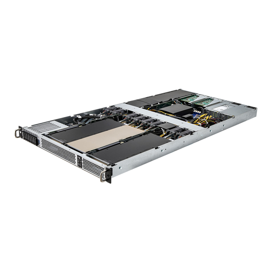
Chapter 2 Server System Overview This chapter provides diagrams showing the location of important components of the server system. 2.1 System Components 2 x Riser Card Brackets 2 x Power Supply Units 1 x GPU Card Slot 8 x System Fans Server Board 3 x GPU Card Slots Front Controls and Indicators... -
Page 9: Internal Features
1U4G-ROME 2.2 Internal Features... - Page 10 Description GPU Card (GPU4) Riser-L Card (for GPU4) Serverboard (MB) 2 x Power Supply Units Power Distribution Board (PDB) System Fan8 System Fan7 System Fan6 System Fan5 System Fan4 System Fan3 System Fan2 System Fan1 Backplane Board (BPB) 8 x SSD Drive Trays Riser-L Card (for GPU1) GPU Card (GPU1) GPU Card (GPU2)
-
Page 11: System Front Panel
1U4G-ROME 2.3 System Front Panel Description 8 x NVMe SSD Drives (EDSFF-S (E1.S) or M.2 (ED_M2W_G4) 1 x USB 3.2 Gen1 Port Control Panel Buttons and LEDs Front Vent 2.4 System Rear Panel Description 2 x Power Supply Units I/O Shield... -
Page 12: Front Control Panel Buttons And Leds
2.5 Front Control Panel Buttons and LEDs Front Control Panel Description UID Button Power Button System Reset Button Power LED LAN1 Activity LED LAN2 Activity LED System Fail LED *Please be noted that the functions are supported depending on the type of the server board. UID Button Press the ID button to toggle the front panel UID LED and the baseboard UID LED on and off. - Page 13 1U4G-ROME LAN1, LAN2 LED Status Description Yellow Link between system and network or no access Blinking Yellow Network access System Fail LED Status Description Running or normal operation At least one sensor has critical alert...
-
Page 14: Drive Tray Leds
2.6 Drive Tray LEDs Description HDD Power & Activity LED (ED_M2W_G4) HDD Power & Activity LED (E1.S) Status LED Definitions HDD Activity LED Status Description HDD present, no activity Blinking HDD accessing or rebuild HDD not present HDD Power LED Status Description Power on / Card populated... -
Page 15: Chapter 3 Hardware Installation And Maintenance
1U4G-ROME Chapter 3 Hardware Installation and Maintenance This chapter helps you assemble the chassis and install components. Before You Begin Before you work with the server, pay close attention to the “Important Safety Instructions” at the beginning of this manual. -
Page 16: Server Top Cover
3.1 Server Top Cover Removing the Server Top Covers 1. Before removing the top cover, power off the server and unplug the power cord. 2. The system must be operated with the chassis top cover installed to ensure proper cooling. Top Rear Cover Top Front Cover 1. - Page 17 1U4G-ROME Installing the Server Top Covers Top Rear Cover Top Front Cover 1. Lower the top FRONT cover on the chassis, making sure the side latches align with the cutouts. Slide the top front cover toward the REAR. 2. Secure the top front cover with the screws.
-
Page 18: Ssd Drive (Edsff Short/E1.S)
3.2 SSD Drive (EDSFF Short/E1.S) Installing EDSFF-S Solid State Drives 1. Rotate the lever out and away from the drive bay. 2. Pull the hard drive tray out of the chassis. Attention! If a M.2 SSD (ED_M2W_G4) is installed in the drive tray, remove the M.2 SSD and its standoff before installing an EDSFF-S SSD. - Page 19 1U4G-ROME 3. Install an EDSFF-S SSD drive on the drive tray and secure it with screws. EDSFF-S(E1.S) SSD Drive Drive Tray 4. Insert the drive tray into the drive bay. 5. When it is about to fully inserted, push in the lever to lock the drive tray into place.
-
Page 20: Ssd Drive (M.2/Ed_M2W_G4)
3.3 SSD Drive (M.2/ED_M2W_G4) Installing M.2 Solid State Drives 1. Rotate the lever out and away from the drive bay. 2. Pull the hard drive tray out of the chassis. - Page 21 1U4G-ROME Attention! Remove the EDSFF-S SSD if it is installed in the drive tray. 3. Install the M.2 adapter board and secure it with screws. M.2 Adapter Board 4. Depending on the length of your M.2 module, find the corresponding nut location to be used.
- Page 22 5. Install the M.2 module. 6. Tighten the screw with a screwdriver to secure the module into place. Please do not overtighten the screw as this might damage the module.
- Page 23 1U4G-ROME 7. Insert the drive tray into the drive bay. 8. When it is about to fully inserted, push in the lever to lock the drive tray into place. 9. Reverse the procedures to remove the M.2 SSD drive.
-
Page 24: Power Supply
Installing and Removing the Power Supply Installing the Power Supply Unit The 1U4G-ROME Series can accommodate two AC or two DC power supplies in the bay at the rear of the chassis. Each unit provides up to 2000 or 2200 Watts of power... - Page 25 1U4G-ROME Removing the Power Supply Unit To remove a failed power supply, identify the failed power supply by checking the power supply LED on the PSU. 1. Hold onto the power supply handle while pressing the locking lever towards the power supply handle.
-
Page 26: System Fan
3.5 System Fan Replacing the Simple-Swap Fan 1. Open the chassis covers and lift the failed fan from the chassis. 2. Place the new fan into the vacant space in the housing while making sure the mounting holes on the fan bar are aligned with the fan mounts on the fan. 3. -
Page 27: Add-On Card
1U4G-ROME 3.6 Add-on Card 1. You can install an add-on card to the chassis only when you have a riser card installed on the server board. 2. Before installing the add-on card, power off the server and unplug the power cord. - Page 28 Installing the Add-on Card 1. Install the add-on card to the riser card bracket. 2. Secure the add-on card to the bracket with one screw. 3. Align the riser card assembly with the openings of the chassis. Make sure it is properly installed.
- Page 29 1U4G-ROME Left Add-on Card Slot Removing the Blanking Plate from the Chassis 1. Lift up the riser card bracket. 2. Remove the screw securing the blanking plate to the riser card bracket. 3. Slide the blanking plate out sideways.
- Page 30 Installing the Add-on Card 1. Install the add-on card to the riser card bracket. 2. Secure the add-on card to the bracket with one screw. 3. Align the riser card assembly with the openings of the chassis. Make sure it is properly installed.
-
Page 31: Gpu Card (For Gpu1 / Gpu2 / Gpu3 Slot)
1U4G-ROME 3.7 GPU Card (for GPU1 / GPU2 / GPU3 Slot) 1. Before installing the add-on card, power off the server and unplug the power cord. 2. Before installing GPU2, be sure to remove GPU3 first. 1. Release the screws. Keep them for later use. - Page 32 6. Install the PCIE card to the riser card bracket. 7. Install the mounting bracket back to the riser card bracket and secure it with screws. (This step is for NVIDIA V100/V100S GPU cards only.) Mounting Bracket...
- Page 33 1U4G-ROME 8. Use the screw you set aside in Step 1 to secure the PCIE card to the riser card bracket. (This step is for NVIDIA V100/V100S GPU cards only.) 9. Install the riser card assembly to the PCIE slot on the server board.
-
Page 34: Gpu Card (For Gpu4 Slot)
3.8 GPU Card (for GPU4 Slot) 1. Before installing the add-on card, power off the server and unplug the power cord. 2. Before installing GPU4, be sure to remove the right add-on card first. Please refer to the section entitled “Add-on Card“ for instructions. 1. - Page 35 1U4G-ROME 3. Hand-release the thumbscrew and the screw that secure the riser card bracket to the chassis. 4. Life up and remove the riser card bracket. 5. Release the screw securing the blanking plate to the riser card bracket. 6. Remove the blanking plate sideways.
- Page 36 9. Install the mounting bracket back. 10. Use both screws and thumbscrews to secure the add-on card assembly to the chassis.
Need help?
Do you have a question about the 1U4G-ROME and is the answer not in the manual?
Questions and answers