Table of Contents
Advertisement
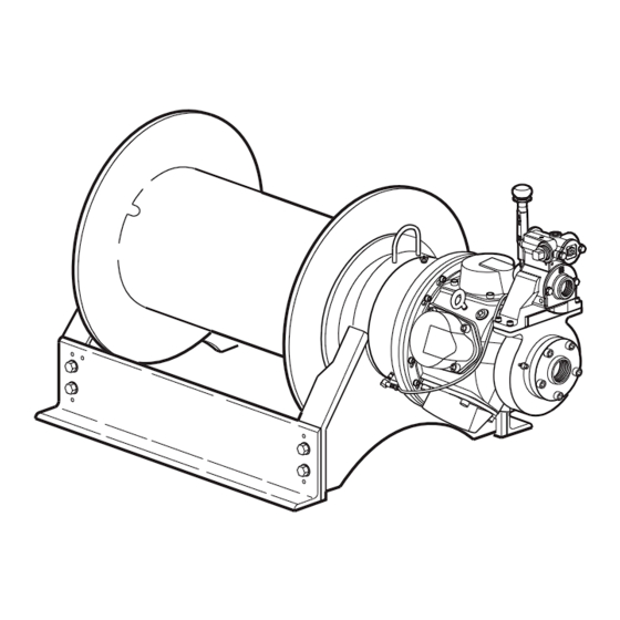
PARTS, OPERATION AND MAINTENANCE MANUAL
READ THIS MANUAL BEFORE USING THESE PRODUCTS. This manual
contains important safety, installation, operation and maintenance
information. Make this manual available to all persons responsible for the
installation, operation and maintenance of these products.
Do not use this winch for lifting, supporting, or transporting people unless winch is
approved for Man Rider
Always operate, inspect and maintain this winch in accordance with American Society of
Mechanical Engineers Standards Safety Code (ASME B30.7) and any other applicable
safety codes and regulations.
Form MHD56037
Edition 5
May 2006
71062103
© 2006 Ingersoll Rand Company
MODEL FA5 AND FA5T
WARNING
applications. Do not lift or support loads over people.
TM
Get other manuals https://www.bkmanuals.com
Form MHD56037
(Dwg. MHP2107)
Advertisement
Chapters
Table of Contents

Related Manuals for Ingersoll-Rand force 5 FA5


Summary of Contents for Ingersoll-Rand force 5 FA5
- Page 1 Form MHD56037 PARTS, OPERATION AND MAINTENANCE MANUAL MODEL FA5 AND FA5T (Dwg. MHP2107) READ THIS MANUAL BEFORE USING THESE PRODUCTS. This manual contains important safety, installation, operation and maintenance information. Make this manual available to all persons responsible for the installation, operation and maintenance of these products.
-
Page 2: Table Of Contents
TABLE OF CONTENTS Description Page No. Safety Information Danger, Caution, Warning and Notice ................3 Safe Operating Instructions . -
Page 3: Safety Information
SAFETY INFORMATION This manual provides important information for all personnel The Occupational Safety and Health Act of 1970 generally places involved with the safe installation, operation and proper the burden of compliance with the user, not the manufacturer. maintenance of this product. Even if you feel you are familiar Many OSHA requirements are not concerned or connected with with this or similar equipment, you should read this manual the manufactured product but are, rather, associated with the final... -
Page 4: Safe Operating Instructions
SAFE OPERATING INSTRUCTIONS The following warnings and operating instructions have been Never lift a load greater than rated capacity of the winch. adapted in part from American Society of Mechanical Engineers Refer to labels attached to winch or to “SPECIFICATIONS” (Safety) Standard ASME B30.7 and are intended to avoid unsafe section. -
Page 5: Specifications
SPECIFICATIONS Model Code Explanation Example: FA5-24MK320P Series (Capacity) = Air Powered Winch (5 metric ton / 11,000 lbs.) Drum Flange Height or Man Rider ® = Standard flange: 27 inch (660 mm) diameter = Tall flange: 35 inch (890 mm) diameter = Man Rider (Refer to FA5 Man Rider Supplement Form #MHD56042) -
Page 6: Performance Graphs
Performance Graphs FA5 Winch (Dwg. MHP1890) FA5T Winch (Dwg. MHP1891) MHD56037 - Edition 5 Get other manuals https://www.bkmanuals.com... -
Page 7: General Specifications
Model General Specifications: FA5T Rated Operating Pressure 90 psig (6.3 bar) Air System Air Consumption 700 scfm 20 cu.m/min. 700 scfm 20 cu.m/min. (at rated pressure and load) Full Drum Line Pull 11,000 lbs 4,490 kgs 8,400 lbs 3,810 kgs Mid Drum Line Speed 65 fpm 20 m/min. -
Page 8: Traceability
M2–Material Traceability certificates according to EN 10204 (Ex Traceability DIN 50049) 3.1b on load bearing parts. Conformity documents affirm (by a department independent of the manufacturing Load bearing parts are documented to provide traceability. The department) that the actual parts are in compliance with the documentation includes chemical and physical properties of raw requirements of the order based on specific inspection and testing material, heat treating, hardening, tensile and charpy tests as... -
Page 9: Wire Rope
Table 2–Winch Bolt Hole Mounting Dimensions Wire Rope Drum Length (inches) Dimension CAUTION inch 31.25 “A” FA5 - - - • Maintain at least 3 tight wraps of wire rope on drum at all times. • Install wire rope to come off drum for overwind operation. inch 34.25 “A”... -
Page 10: Air Supply
Support wire rope spool and have wire rope come off top of spool Installing Wire Rope and over top of winch drum. This will prevent damage to wire rope. CAUTION Spooling Wire Rope onto Winch Drum • To avoid disc brake damage when installing wire rope pressurize brake with a minimum of 60 psi (4.1 bar) air from an auxiliary source. -
Page 11: Motor
Air Lines Air Pressure Regulator Inside diameter of winch air supply lines must not be less than If an air pressure regulator is used, install between lubricator and sizes shown in Table 4 on page 11. Before making final filter. Refer to Dwg. MHP0191 on page 11. connections, all air supply lines should be purged with clean, moisture free air or nitrogen before connecting to winch inlet. -
Page 12: Constant Tension
Emergency Stop and Overload System Components Constant Tension (optional feature) (old style) Refer to Dwg. MHP1865 on page 12 and Dwg. MHP1176 on page 12. The air supply line is connected to one of the two top ports on the control valve. -
Page 13: Initial Operating Checks
For winches that have been in storage the following start-up Initial Operating Checks procedures are required. Give the winch an inspection conforming to requirements of Winches are tested for proper operation prior to leaving factory. “Winches Not in Regular Use” in the “INSPECTION” Before winch is placed into service the following initial operating section. -
Page 14: Underwound Operation
Winch Mounted Throttle Control Valve Operation (old style) (Dwg. MHP2043) Remote Pilot Pendant Throttle (optional feature) Refer to Dwg. MHP2233 on page 14 and MHP1311 on page 15. Provides for remote winch control at distances of up to 50* feet (15 metres) away from winch. -
Page 15: Emergency Stop And Overload System
Pendant Hose and Operating Levers (old style) Emergency Stop Operation (Dwg. MHP1311) (Dwg. MHP2047) * For distances greater than 50 feet (15 metres) contact Ingersoll Rand Technical Sales for control suitability. NOTICE Remote Pilot Lever Throttle (optional feature) • If winch overload occurs, overload device, if equipped, also stops winch. -
Page 16: Overload Device
To operate winch, depress appropriate ‘Haul-in’ or ‘Payout’ Overload Device lever. In event of an emergency all winch operation can be stopped An overload device is available on winches with the emergency by pushing the emergency stop button. This will prevent air shutoff option. -
Page 17: Winch Overload Device
Remote Pendant Emergency Stop Valve Operation WARNING • Ensure slack load line is taken up by operating winch control valve with selector in NORMAL position. If selector lever is placed in TENSION position the winch will immediately attempt to establish line tension causing line to ‘snap’ resulting in injury or damage to property. -
Page 18: Limit Switch
pull rod and ensure locking pin engages and is seated in drum hole and gland deep groove. WARNING • Ensure that all braking mechanisms are engaged and all personnel are clear of winch load and rigging before disengaging locking pin. •... -
Page 19: Lubrication
LUBRICATION To ensure continued satisfactory operation of winch, all points Recommended Grease requiring lubrication must be serviced with correct lubricant at proper time interval as indicated for each assembly. Temperature Type Oil The lubrication intervals recommended in this manual are based -20°... - Page 20 K5B Motor Lubrication Locations To ensure correct performance, highest efficiency and long life, it is essential that lubricating oil be maintained at correct level. Rotate drum until fill plug is located at top dead center then add oil up to level plug hole. Oil capacity for reduction gear assembly is 4 quarts (3.8 litres).
-
Page 21: Inspection
If drum locking pin is disassembled, clean all parts thoroughly Drum Locking Pin (optional feature) and coat with clean grease. Refer to ‘Recommended Lubricants’ section. Use sufficient grease to provide a good protective coat. Refer to Dwg. MHP0155 on page 61. Lubricate at least once every month, depending on environment Lubrication will help to prevent rust and allow easier locking pin and duty cycle, through grease fitting (139) located in gland (138) -
Page 22: Periodic Inspection
10. MOTOR. During operation check motor housing for excess ALL COMPONENTS. Inspect for wear, damage, distortion, heat build up. Housing should not be hot to touch. Listen for deformation and cleanliness. If external evidence indicates grinding or knocking noises. Ensure lubricated air supply damage, disassemble as required to conduct a detailed provides 6 to 9 drops per minute of ISO VG 32 (SAE 10W) inspection. -
Page 23: Inspection And Maintenance Report
Refer to the Parts, Operation and Maintenance Manual “INSPECTION” section for general inspection criteria. Also, refer to appropriate National Standards and Codes of practice. If in doubt about an existing condition, contact the nearest Ingersoll-Rand Distributor or the factory for technical assistance. -
Page 24: Troubleshooting
TROUBLESHOOTING This section provides basic troubleshooting information. Determination of specific causes to problems are best identified by thorough inspections performed by personnel instructed in safety, operation and maintenance of this equipment. The chart below provides a brief guide to common winch symptoms, probable causes and remedies. SYMPTOM CAUSE REMEDY... - Page 25 SYMPTOM CAUSE REMEDY Automatic Disc Brake: Brake fails to release. Low air supply pressure. Ensure air pressure at inlet to disc brake is at least 50 psig (3.4 bar/340 kPa). Leaking piston seals. Inspect brake breather. If air escapes from brake breather when attempting to release brake, replace brake seals.
-
Page 26: Maintenance
MAINTENANCE Rotate link stud (103) clockwise to increase brake torque. WARNING Install pin (101) and check adjustment. Brake should be adjusted until brake lever over center • Never perform maintenance on winch while it is supporting a position can be attained with 50 to 100 lb. (23 to 45 kg) load. - Page 27 Rotating adjustment screw counterclockwise will decrease Overload Valve Adjustment (old style) pressure required to activate overload valve. Overload Valve Adjustment (new style) (Dwg. MHP1678) (Dwg. MHP2216) Limit Switch Adjustment (optional feature) Overload Valve Adjustment (optional feature) old style Refer to Dwg. MHP1678 on page 27. Adjust overload valve by turning adjustment screw located at bottom of valve.
-
Page 28: Disassembly
Hold cam adjustment screw in position (venting air) and Disassembly tighten red setscrew. If required, adjust payout limit switch. Test winch set points General Disassembly Instructions by operating winch through three complete cycles to ensure consistent limit switch operation within +/- 2 feet (2/3 metre) The following instructions provide necessary information to of set points. - Page 29 Drain oil from reduction gear assembly by removing one To disassemble reduction gear refer to Reduction Gear plug (48) when positioned at it’s lowest point, and one plug Disassembly section. (48) from it’s highest point to vent. Refer to Dwg. MHP0140 on page 20 in “LUBRICATION”...
- Page 30 Control Valve Removal and Replacement NOTICE Refer to Dwg. MHP2036 on page 50 or MHP0165 on page 54. • Do not disassemble planetary gear assemblies (54), (58) and Replacement of K5B control valve with K5C2 control valve. (67). Turn off air supply to valve and disconnect main air supply line at motor.
-
Page 31: K5C2 Control Valve Disassembly
Move reverse valve (943) out exhaust flange side of housing Piston Removal until ball (916) is visible on reverse valve. Allow ball (916) to drop out of bushing (944) and remove ball (916). Remove capscrews (901) and washers (902) from piston Remove bushing (944) out exhaust flange side of housing. -
Page 32: Assembly
Inspect drum band brake lining for oil, grease and glazing. If Holding ball (916) in position on reverse valve platform, drum band brake lining is oil-soaked replace brake bands as rotate reverse valve from neutral position to approximately a set. Remove glazed areas of band brake lining by sanding 45 degrees in either direction. -
Page 33: K5C2E Control Valve Assembly
Place handle assembly over reverse valve end. Slide handle Pilot Valve Assembly will have to be lifted slightly to allow pin to fit into slot in seal bracket. Follow assembly instructions for K5C2 Control Valve. Secure handle assembly (930) to reverse valve with tab lock washer (909) and capscrew (901), torque to 15 ft lbs. - Page 34 Install two seal rings (251) on each end of rotary valve NOTICE (250). Place bearing (252) onto the rear of rotary valve (250) and press into position. Press only on bearing inner race. • ‘O’ ring, item 5 listed in step 24 refers to part number 51459 With rotary valve housing (247) exhaust flange down, install as shown on winch assembly Dwg.
- Page 35 18. Align capscrew and dowel holes and install cover (73). Use a 14. Install one brake spring (9) in each brake spring holes. soft hammer or mallet to carefully tap the cover until flush 15. Lubricate and install ‘O’ ring (33) in groove on brake with ring gear (72).
- Page 36 25. Install the motor assembly to motor mounting plate using Install stop plate (126) on inside of side rail (82) with capscrews (4) and lockwashers (3). Lightly coat capscrew capscrew (119) and washer (117). Install adjusting screw threads with Loctite 242 and torque to 85 ft lbs (115 Nm).
-
Page 37: Testing
Testing Operational Test Prior to initial use, all new or repaired winches shall be tested to ensure proper operation. Check oil level in motor, reduction gear assembly and disc brake are correct. Top off levels as required before operation as described in the “LUBRICATION” section. To initially ‘break in’... -
Page 38: Fa5 Winch Assembly Drawings Reference Diagram
FA5 WINCH ASSEMBLY DRAWINGS REFERENCE DIAGRAM (Dwg. MHP1493) MHD56037 - Edition 5 Get other manuals https://www.bkmanuals.com... -
Page 39: Fa5 Winch Drawings And Parts Lists Table Of Contents
FA5 WINCH DRAWINGS AND PARTS LISTS TABLE OF CONTENTS Description Page No. Drum, Base and Reduction Gear Assembly Drawing (Dwg. MHP0157) ........... . 40 Drum, Base and Reduction Gear Assembly Parts List . -
Page 40: Fa5 Winch Drawings And Parts Lists
DRUM, BASE AND REDUCTION GEAR ASSEMBLY DRAWING (Dwg. MHP0157) MHD56037 - Edition 5 Get other manuals https://www.bkmanuals.com... -
Page 41: Drum, Base And Reduction Gear Assembly Parts List
Seal sleeve, item 44 is no longer used and is not available as a replacement part. For units purchased with seal sleeves requiring replacement contact your Ingersoll-Rand distributor or factory. Serial numbers A1480801 and above will have new reduction gear 28744, drive shaft 28738 and sun gear 28826. Winches with Serial numbers below A1480801 needing reduction gear parts will have to purchase new reduction gear and drive shaft 28738. -
Page 42: Drum, Base And Reduction Gear Assembly Parts List (Continued)
DRUM, BASE AND REDUCTION GEAR ASSEMBLY PARTS LIST (CONT’D) UPRIGHT ASSEMBLY PARTS LIST Inboard Upright Total Part Outboard Upright Total Part (Item 42) Number (Item 84) Number Standard Drum Flange (27 inch) † 10789 Standard Drum Flange (27 inch) † 10790 Tall Drum Flange (35 inch) †... -
Page 43: Muffler Assembly Drawing (Dwg. Mhp2090) And Parts List
MUFFLER ASSEMBLY DRAWING AND PARTS LIST K5C2 Control Valve K5B Motor Mufflers with Remote Muffler Assembly Actuated Pilot Control Valve K5B Motor Muffler with Round Exhaust K5B Motor Muffler and K5B Control Manifold K5B Control Valve with Muffler Valve with Long Exhaust Manifold (Dwg. -
Page 44: K5B Motor Assembly Drawing (Dwg. Mhp2093)
K5B MOTOR ASSEMBLY DRAWING K5C2 Valve K5B Valve (Dwg. MHP2093) MHD56037 - Edition 5 Get other manuals https://www.bkmanuals.com... -
Page 45: K5B Motor Assembly Parts List
K5B MOTOR ASSEMBLY PARTS LIST Item Description Total Part Item Description Total Part of Part Number of Part Number Motor Assembly Oil Slinger K5B-540 with Control Valve * K5B-546M-S Crank Assembly K5B-A516 without Control Valve * K5B-546LM-S Sleeve K5B-519 Capscrew 51471 Bushing K5B-511... -
Page 46: Disc Brake Assembly Drawing (Dwg. Mhp0152)
DISC BRAKE ASSEMBLY DRAWING Note: Tee fitting for use on units with Disc and Auto Band Brake only. (Dwg. MHP0152) MHD56037 - Edition 5 Get other manuals https://www.bkmanuals.com... -
Page 47: Disc Brake Assembly Parts List
DISC BRAKE ASSEMBLY PARTS LIST Item Description Total Part of Part Number Brake Assembly (includes items 1, 7 through 32 and 44) 11366 Capscrew (with Disc Brake) 51471 Oil Seal 51873 Motor Adapter 14227 Shaft Extender 10594 Brake Reaction Plate 10597 Spring 50751... -
Page 48: Drum Brake Assembly Drawing (Dwg. Mhp0153)
DRUM BRAKE ASSEMBLY DRAWING (Dwg. MHP0153) MHD56037 - Edition 5 Get other manuals https://www.bkmanuals.com... -
Page 49: Drum Brake Assembly Parts List
DRUM BRAKE ASSEMBLY PARTS LIST Part Number Item Description Total of Part Manual Brake Automatic Brake Drum with band brake Refer to page 42 Side Rail, Right Hand Refer to page 42 Side Rail, Left Hand Common Parts: Pin † 4308-S 4308-S Cotter Pin... -
Page 50: K5C2 Control Valve Assembly Drawing (Dwg. Mhp2036)
K5C2 CONTROL VALVE ASSEMBLY DRAWING Note: Brake Fitting Old Version K5C Control Valve Optional 0.720 New Style Piston (922) Shown From Cap (906) End (Dwg. MHP2036) * Item 920 is not sold with any valve parts, must be purchased separately. MHD56037 - Edition 5 Get other manuals https://www.bkmanuals.com... -
Page 51: K5C2 Control Valve Assembly Parts List
K5C2 CONTROL VALVE ASSEMBLY PARTS LIST Item Description Total Part Item Description Total Part of Part Number of Part Number Control Valve Assembly K5C2-X Seal Bracket (Note 3) 28733-S Capscrew 71342034 Tag, No FA2B 71392757 Washer 71303408 ‘O’ Ring 71357198 Cover, Poppet 26997 ‘O’... -
Page 52: Emergency Stop And Overload K5C2-Ex Valve Assembly Drawing (Dwg. Mhp2180)
EMERGENCY STOP AND OVERLOAD K5C2-EX VALVE ASSEMBLY DRAWING Note: Brake Fitting 0.720 New Style Piston (922) Shown From Cap (906) End (Dwg. MHP2180) MHD56037 - Edition 5 Get other manuals https://www.bkmanuals.com... -
Page 53: Emergency Stop And Overload K5C2-Ex Valve Assembly Parts List
EMERGENCY STOP AND OVERLOAD K5C2-EX VALVE PARTS LIST Item Description Total Part Item Description Total Part of Part Number of Part Number Control Valve Assembly K5C2-EX IR Pilot Valve Tool (MHP2036) 26998 27491 ‘O’ Ring 52537 Grommet 71365779 Piston (Note 2) 28735-S Plunger 27490... -
Page 54: K5B Control Valve Assembly Drawing (Dwg. Mhp0165) And Parts List
K5B CONTROL VALVE ASSEMBLY DRAWING AND PARTS LIST (old style) (Dwg. MHP0165) Item Description Total Part of Part Number Not available; order Valve Assembly (Includes item 96, 246 and 300 through 318) K5C2-X Valve on page 51 Lockwasher 50200 Grease Fitting 53095 Handle K5B-556... -
Page 55: Full Flow Remote Control Valve Assembly Drawing (Dwg. Mhp2092) And Parts List
FULL FLOW REMOTE CONTROL VALVE ASSEMBLY DRAWING AND PARTS LIST (Dwg. MHP2092) Item Description Total Part of Part Number Capscrew 51471 Hose End 51029 Hose (bulk) As Req’d 50923 Gasket K5B-928 Exhaust Cover KK5B-276M Control Valve Assembly K5C2-SBK Fitting, Elbow 54270 Hose End 54738... -
Page 56: Remote Pilot Air Control (Optional) Assembly Drawing (Dwg. Mhp0167)
REMOTE PILOT AIR CONTROL (OPTIONAL) ASSEMBLY DRAWING Brake Remote Pilot Remote Pilot Lever Throttle Pendant Throttle Old Style Pendant Throttle (Dwg. MHP0167) MHD56037 - Edition 5 Get other manuals https://www.bkmanuals.com... -
Page 57: Remote Pilot Air Control (Optional) Assembly Parts List
REMOTE PILOT AIR CONTROL (OPTIONAL) ASSEMBLY PARTS LIST Item Description Total Part of Part Number Lockwasher 50200 Capscrew 51780 Fitting, Hose End – Disc Brake Only 51029 Fitting, Hose End – Disc and Automatic Drum Brake Hose, Bulk As Req’d 50923 Gasket (item not illustrated) K5B-547... -
Page 58: Remote Pendant Assembly Drawings (Dwg. Mhp2346 And Mhp1677)
REMOTE PENDANT ASSEMBLY DRAWINGS Pendant without Emergency Stop (Dwg. MHP2346) Pendant with Emergency Stop (Dwg. MHP1677) MHD56037 - Edition 5 Get other manuals https://www.bkmanuals.com... -
Page 59: Remote Pendant Assembly Parts List
REMOTE PENDANT ASSEMBLY PARTS LIST Part Item Description Total Number of Part With E-Stop Without E-Stop Pendant Assembly* PHS2E PHS2E-U Lifting Eye 64222332 Emergency Stop Valve 95790108 - - - Plug 95790106 • 443 ‘O’ Ring 2(5) 58209229 Plug 2(4) 54292 Spring 2(4) -
Page 60: Pilot Air Control Valve (Optional) Assembly Drawing (Dwg. Mhp0141) And Parts List
PILOT AIR CONTROL VALVE (OPTIONAL) ASSEMBLY DRAWING AND PARTS LIST (Dwg. MHP0141) Part Number Item Description Total of Part 510 size Valve Assembly (includes items 265 through 280) 20993 End Cap 71136725 Gasket 71136733 Valve Body Not sold separately, order item 355 End Cap Assembly (includes items 270 and 271) 25591 Capscrew... -
Page 61: Drum Locking Pin (Optional) Assembly Drawing (Dwg. Mhp0155) And Parts List
DRUM LOCKING PIN (OPTIONAL) ASSEMBLY DRAWING AND PARTS LIST OLD STYLE (Dwg. MHP0155) Item Description Total Part Item Description Total Part of Part Number of Part Number 27 inch Standard Flange Drum (old style) 35 inch Tall Flange Drum (old style) 12 inch with band brake 10860–2 12 inch with band brake... -
Page 62: Drum Guard Assembly Drawing (Dwg. Mhp0154) And Parts List
DRUM GUARD ASSEMBLY DRAWING AND PARTS LIST (Dwg. MHP0154) Part Number Item Description Total of Part Standard Flange Tall Flange Drum Guard Assembly (includes items 3, 96 and 150 through 158) 12 inch long drum 10925-2 10927-2 16 inch long drum 10925-3 10927-3 24 inch long drum... -
Page 63: Emergency Stop Valve And Overload Assembly Drawing (Dwg. Mhp1341) And Parts List
EMERGENCY STOP VALVE, OVERLOAD ASSEMBLY DRAWING AND PARTS LIST (old style) (Dwg. MHP1341) Item Description Total Part Item Description Total Part of Part Number of Part Number Washer 50200 Valve, Shut-off 25541 Hose End 51029 Fitting, Nipple 52191 Hose (bulk) As Req’d 50923 Pilot Valve... -
Page 64: Pendant Control Assembly (Optional) Drawing (Dwg. Mhp0168) And Parts List
PENDANT CONTROL ASSEMBLY DRAWING AND PARTS LIST (old style) (Dwg. MHP0168) Item Description Total Part of Part Number Fitting, Adapter 71048268 Pendant Assembly (includes items 370–381 and 383) No longer available Order item 353 Pendant Handle (only available as part of assembly item 352) on page 59 Throttle Valve MLK-K264B... - Page 65 SERVICE NOTES MHD56037 - Edition 5 Get other manuals https://www.bkmanuals.com...
-
Page 66: Emergency Stop Overload Assembly Drawing (Dwg. Mhp1488)
EMERGENCY STOP OVERLOAD ASSEMBLY DRAWING (Dwg. MHP1488) MHD56037 - Edition 5 Get other manuals https://www.bkmanuals.com... -
Page 67: Emergency Stop Overload Assembly Parts List
EMERGENCY STOP OVERLOAD ASSEMBLY PARTS LIST Item Description Total Part Item Description Total Part of Part Number of Part Number Fitting, Tee 52181 Muffler 52472 Hose End 51029 Fitting, Connector 71078158 Hose (bulk) As Req’d 50923 Fitting, Tee 71067789 Fitting, Nipple 71057483 Delta ‘P’... -
Page 68: Limit Switch Assembly Drawing (Dwg. Mhp2027)
LIMIT SWITCH ASSEMBLY DRAWING (Dwg. MHP2027) MHD56037 - Edition 5 Get other manuals https://www.bkmanuals.com... -
Page 69: Limit Switch Assembly Parts List
LIMIT SWITCH ASSEMBLY PARTS LIST Item Description Total Part of Part Number Capscrew 51086 Lockwasher 50200 Capscrew 51780 Hose As Req’d 50923 Fitting, Elbow 51281 Fitting, Elbow 52179 Retainer (replaces Retainer, item 191, on standard winch) 11485 Washer 71372114 Buttonhead Screw 71393409 Bracket, Limit Switch 29102... -
Page 70: Pilot Air Valve Plumbing Assembly Drawing (Dwg. Mhp1679)
PILOT AIR VALVE PLUMBING ASSEMBLY DRAWING Note: This drawing is for Pilot Air Valve Assembly with Limit Switch. For Remote Pilot Air installation refer to Dwg. MHP0167 on page 56. (Dwg. MHP1679) MHD56037 - Edition 5 Get other manuals https://www.bkmanuals.com... -
Page 71: Pilot Air Valve Plumbing Assembly Parts List
PILOT AIR VALVE PLUMBING ASSEMBLY PARTS LIST Item Description Total Part of Part Number Washer 50200 Capscrew 51780 Fitting, Hose End 51029 Hose (bulk) As Req’d 50923 Capscrew 71030118 Fitting, Elbow 52182 Capscrew 54681 Washer 50893 Adapter Manifold 13881 Fitting, Tee 54678 Fitting, Connector 51814... -
Page 72: Tensioning Manifold Assembly Drawing (Dwg. Mhp2028)
TENSIONING MANIFOLD ASSEMBLY DRAWING (Dwg. MHP2028) MHD56037 - Edition 5 Get other manuals https://www.bkmanuals.com... -
Page 73: Tensioning Manifold Assembly Parts List
TENSIONING MANIFOLD ASSEMBLY PARTS LIST Item Description Total Part of Part Number Fitting, Hose End 51029 Hose (bulk) As Req’d 50923 Gasket K5B-547 Control Valve Assembly K5B-REMOTE Shuttle Valve 50277 Washer 71320964 Capscrew 71127054 Rivet 50915 Label, Tensioning Manifold 26217 Gasket 26216 Cover... -
Page 74: Air Preparation Assembly Drawing (Dwg. Mhp0223) And Parts List
AIR PREPARATION ASSEMBLY DRAWING AND PARTS LIST (Dwg. MHP0223) Note: Drawing for reference only; components may not resemble those shown in drawing. Item Description Total Part of Part Number Filter (1–1/2 FNPT) F35-0B-C28 Regulator (1–1/2 FNPT) R40-0B-G00 Pipe Nipple (1-1/2 FNPT*) As Req’d Lubricator (1–1/2 FNPT) L40-0B-G00... -
Page 75: Labels And Tags Replacement Drawing (Dwg. Mhp1676) And Parts List
LABELS AND TAGS (Dwg. MHP1676) Item Description Total Part Item Description Total Part of Part Number of Part Number 22261-4-S Product Label 12-16 in. long drum 71111777 Label and Tag Kit * Product Label 24 in. and longer 22261-5-S 71109508 drum 24305-4-S Warning Label... - Page 76 KITS Description Part of Kit Number Automatic Brake Kit (converts manual band brake to automatic band brake). Refer to Dwg. MHP0153on FA5-ABK page 48; includes items 102, 105 through 115, 117 through 120, 129 and 134. Disc Brake Kit (adds disc brake to winch). Refer to Dwgs. MHP0152on page 46 and MHP0157on page 40; FA5-DBRK includes items 1, 7–12, 16–32, 34–38) Full Flow Remote Control Kit (converts winch live air control valve to remote control)
- Page 77 PARTS ORDERING INFORMATION Use of other than Ingersoll Rand replacement parts may Return Goods Policy adversely affect the safe operation and performance of this product. Ingersoll Rand will not accept any returned goods for warranty or service work unless prior arrangements have been made and For your convenience and future reference it is recommended that written authorization has been provided from the location where the following information be recorded.
- Page 78 SERVICE NOTES MHD56037 - Edition 5 Get other manuals https://www.bkmanuals.com...
-
Page 79: Warranty
WARRANTY LIMITED WARRANTY Ingersoll Rand Company (I-R) warrants to the original user its I-R makes no other warranty, and all implied warranties Hoists and Winches (Products) to be free of defects in material including any warranty of merchantability or fitness for a and workmanship for a period of one year from the date of particular purpose are limited to the duration of the purchase. - Page 80 www.winchandhoistsolutions.com Get other manuals https://www.bkmanuals.com...
Need help?
Do you have a question about the force 5 FA5 and is the answer not in the manual?
Questions and answers