
Subscribe to Our Youtube Channel
Related Manuals for Ingersoll-Rand FORCE 5i FA7i


Summary of Contents for Ingersoll-Rand FORCE 5i FA7i
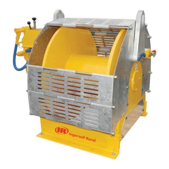
- Page 1 Product Maintenance Information FORCE 5i Air Winch Models FA7i, FA7Ti, FA7Ti-GL and FA7Ti-PL (Dwg. MHP2919) Save These Instructions Form MHD56398 Edition 3 October 2013 45877164 2013 Ingersoll-Rand ©...
-
Page 2: Periodic Inspection
Only allow trained technicians to perform maintenance on this product. For additional information contact factory or nearest Ingersoll Rand Ingersoll Rand Distributor. For additional supporting documentation refer to Table 1 ‘Product Information Manuals’ on page 2. Manuals can be downloaded from http://www.ingersollrandproducts.com. The use of other than genuine Ingersoll Rand replacement parts may result in safety hazards, decreased performance and increased maintenance and will invalidate all warranties. -
Page 3: Records And Reports
Table 2: Inspection Classifications Conditions Normal Heavy Severe Typical Use (operating time) Infrequent Regular Continual/Constant Load Range 60% of Capacity 75% of Times Used 80% of Capacity 75% of Times Used 100% of Capacity 75% of Times Used Installation Protected/Enclosed/Dry Not Sheltered/Exterior Full Exposure Atmosphere... - Page 4 Table 3: Maintenance Interval Chart Normal Application The following work can be completed by owner maintenance personnel System Air Filter Inspect system air filter every 45 days or 150 hours Grease Fittings Lubricate grease fittings every 180 days or 500 hours Gearbox Oil Level Check oil level in gearbox every 120 days or 340 hours It is recommended that the following work be completed by an Ingersoll Rand trained service technician.
-
Page 5: Inspection Report
INSPECTION REPORT Ingersoll Rand Force 5 Infinity Series FA7i and FA7Ti Air Winches Model Number: Date: Serial Number: Inspected by: Reason for Inspection: (Check Applicable Box) 1. Scheduled Periodic Inspection: Operating Environment: (_____ Months _____ Years) 2. Discrepancy(s) noted during Frequent Inspection 3. -
Page 6: Troubleshooting
TROUBLESHOOTING This section provides basic troubleshooting information. Determination of specific causes to problems are best identified by thorough inspections performed by personnel instructed in safety, operation and maintenance of this equipment. The chart below provides a brief guide to common winch symptoms, probable causes and remedies. SYMPTOM CAUSE REMEDY... -
Page 7: Maintenance
MAINTENANCE 5. Install pin (133) and check adjustment. WARNING 6. Brake should be adjusted until brake lever over center position can be attained with 50 to 100 lb. (23 to 45 kg) force on brake lever (104). 7. Install cotter pin (102) when adjustment is completed. Bend ends of cotter pin •... - Page 8 If a product is being completely disassembled for any reason, follow the order of Setting with test load: topics as they are presented. It is recommended that all maintenance work on Actuate auxiliary valve to TENSIONING position. Winch should operate, causing load product be performed in a clean dust-free work area.
- Page 9 28. Remove remaining capscrews (180) and lockwashers (178) that attach siderails 3. Slide reverse valve (943) out exhaust flange side of housing until ball (916) is (98) to outboard upright (184). Drive out dowel pins (181). visible on reverse valve. Allow ball (916) to drop out of bushing (944) and remove 29.
- Page 10 1. Remove capscrews (951) and washers (96) that secure valve to motor on adapter NOTICE (369). Capscrews and washers (96) cannot be removed until adapter is separated from valve body (339). Separate valve as an assembly from winch motor rotary •...
- Page 11 4. Holding ball (916) in position on reverse valve platform, rotate reverse valve from NOTICE neutral position to approximately 45 degrees in either direction. Ball will ‘walk’ up side of reverse valve platform and move in ball hole in bushing (944). •...
- Page 12 Emergency Stop Assembly: Rotary Valve Assembly: 1. Insert spring (711) into valve housing (917). 1. Assemble throttle control valve (900) and gasket (946) to rotary valve housing 2. Place ‘O’ rings (703) on plunger (707). (247) using four capscrews (951) and lockwashers (949). 3.
- Page 13 Brake Seal Installation 21. Align pin holes and install cover (94). Apply Loctite® 242 to eight capscrew (95) threads and install. Refer to “TORQUE CHART” on page 16 for torque requirements. Seal Lip 22. Ensure four plugs (56) are threaded fully into input housing (82) and that fit is tight.
- Page 14 16. Adjust automatic brake as described in 'Adjustments' in the “MAINTENANCE” section. Limit Switch Assembly Refer to Dwg. MHP2677. 1. Secure limit switch assembly to upright (184) with capscrews (97) and washers (96). 2. Install hose connections. Refer to label 71459929 on page 14. Sleeve (Dwg.
- Page 15 2. Install rollers (402) on smaller ends of press roller arm (407) and secure with a. Check oil level in motor, reduction gear assembly and disc brake are correct. capscrews (408) and washers (409). Apply a small amount of Loctite® 242 to b.
-
Page 16: Torque Chart
TORQUE CHART Standard Coarse Thread Torque SAE Grade 5 SAE Grade 8 Size Lubricated PTFE Lubricated PTFE 1/4-20 8-10 12-14 9-10 5/16-18 17-20 13-15 25-28 18-21 11-13 3/8-16 31-35 23-26 14-16 44-49 33-37 20-22 7/16-14 49-56 37-42 22-25 70-79 52-59 31-36 1/2-13 75-85... - Page 18 www.ingersollrandproducts.com...
Need help?
Do you have a question about the FORCE 5i FA7i and is the answer not in the manual?
Questions and answers