Table of Contents
Advertisement
PARTS, OPERATION AND MAINTENANCE
* This supplement should be used in conjunction with supporting documentation for the
hydraulic motor, disc brake, reduction gear assembly and controls as applicable.
READ THIS MANUAL BEFORE USING THESE PRODUCTS. This manual
contains important safety, installation, and maintenance information. Make
this manual available to all persons responsible for the operation,
installation and maintenance of these products.
Do not use this winch for lifting, supporting, or transporting people or lifting or
supporting loads over people.
Always operate, inspect and maintain this winch in accordance with American National
Standards Institute Safety Code (ASME B30.7) and any other applicable safety codes and
regulations.
Refer all communications to the nearest Ingersoll-Rand Material Handling Office or
Distributor.
Form MHD56181
Edition 1
April 1999
71350573
© 1999 Ingersoll-Rand Company
SUPPLEMENT*
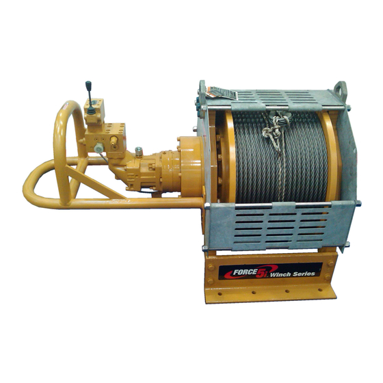
MODEL FH5
WARNING
Form MHD56181
Advertisement
Table of Contents

Related Manuals for Ingersoll-Rand Force 5 FH5


Summary of Contents for Ingersoll-Rand Force 5 FH5
- Page 1 Always operate, inspect and maintain this winch in accordance with American National Standards Institute Safety Code (ASME B30.7) and any other applicable safety codes and regulations. Refer all communications to the nearest Ingersoll-Rand Material Handling Office or Distributor. Form MHD56181...
-
Page 2: Table Of Contents
TABLE OF CONTENTS Description Page No. Safety Information Danger, Caution, Warning and Notice ................3 Safe Operating Instructions . -
Page 3: Safety Information
Safety procedures, precautions and work habits established structural engineer. by accepted industry standards. Ingersoll-Rand cannot know of, or provide all the procedures by NOTICE which product operations or repairs may be conducted and the hazards and/or results of each method. If operation or •... -
Page 4: Safe Operating Instructions
Always rig loads properly and carefully. Be certain the load is properly seated in the saddle of the Ingersoll-Rand recognizes that most companies who use winches hook. Do not tipload the hook as this leads to spreading and have a safety program in force at their facility. In the event that eventual failure of the hook. -
Page 5: Specifications
= Compliance with European Machinery Directive (includes Emergency Stop and Overload Protection) Notes: * Not covered in this manual. Contact the factory or your nearest Ingersoll-Rand distributor for information. ** Documentation, witness testing and material traceability available; must be requested at time of order. Specify options or contact the factory or your nearest Ingersoll-Rand distributor for information. -
Page 6: General Specifications
Model General Specifications: FH5T Utility Rating 5:1 Full Drum Line Pull @ 2700 psi (18620 kPa/ 11,000 lbs 4,490 kgs 8,400 lbs 3810 kgs design factor 186 bar) Mid Drum Line Speed @ 40 gpm (151 l/min) 65 fpm 20 m/min 80 fpm 24 m/min FH5-24MX1 Net Weight... -
Page 7: Installation
Traceability Load bearing parts are documented to provide traceability. The documentation includes chemical and physical properties of the raw material, heat treating, hardening, tensile and charpy tests as required for the part. Units with M2 or M3 in the model code have traceable load-bearing components. -
Page 8: Wire Rope
NOTICE • Some applications may require underwind operation. Consult the factory prior to use. Wire Rope Selection Consult a reputable wire rope manufacturer or distributor for assistance in selecting the appropriate type and size of wire rope and, where necessary, a protective coating. Use a wire rope that provides an adequate safety factor to handle the actual working load and that meets all applicable industry, trade association, federal, state and local regulations. -
Page 9: Hydraulic System
Pull the sleeve over the wire rope end until tight. Check that Table 4 Hydraulic Hose Recommendations the wire rope strands stay in the slots located on the split Oil Flow * Pressure Lines wedge. @ 3000 psig max (inside diameter) Pull the wire rope anchor into position in the drum anchor l/min inch... -
Page 10: Initial Operating Checks
Filters Motor Filters should be equipped with dirty filter indicators, which For optimum performance and maximum durability of parts, should be checked daily. Replace filters if indicators show filter is ensure hydraulic supply does not exceed recommended pressures dirty. It is also recommended that filters be changed if hydraulic and flows. -
Page 11: Operation
OPERATION The four most important aspects of winch operation are: Warm Up Procedure Follow all safety instructions when operating the winch. Allow only people trained in safety and operation of this winch to operate this equipment. CAUTION Subject each winch to a regular inspection and maintenance procedure. -
Page 12: Drum Locking Pin
The counterbalance valve will prevent a runaway load condition. WARNING Should the load try to drop faster than the winch is paying out, over-running the winch motor, the valve will sense a low pressure • Ensure that all braking mechanisms are engaged and all condition at the motor inlet, and restrict fluid flow from the motor personnel are clear of the winch load and rigging before outlet. -
Page 13: Lubrication
Other lubricants may affect the performance of the winch. Approval for the use of other lubricants must be obtained from your Ingersoll-Rand distributor. Failure to observe this Reduction Gear Assembly precaution may result in damage to the winch and/or its associated components. -
Page 14: Automatic Disc Brake
Automatic Disc Brake Wire Rope Refer to the manufacturer’s literature for lubrication requirements. Follow the wire rope manufacturer’s instructions. At a minimum, observe the following guidelines. Clean with a brush or steam to remove dirt, rock dust or other Seals and Bearings foreign material on the surface of the wire rope. -
Page 15: Inspection
INSPECTION Inspection information is based in part on American National WINCH. Prior to operation, visually inspect winch housings, Standards Institute Safety Codes (ASME B30.7). controls, brakes, side rails and drum for indications of damage. Do not operate the winch unless the wire rope feeds onto the drum smoothly, and any discrepancies noted have WARNING been reviewed and inspected further by personnel instructed... -
Page 16: Winches Not In Regular Use
WIRE ROPE. In addition to Frequent Inspection ALL COMPONENTS. Inspect for wear, damage, distortion, requirements, also inspect for the following: deformation and cleanliness. If external evidence indicates Build-up of dirt and corrosion. Clean with steam or a damage, disassemble as required to conduct a detailed stiff wire brush to remove dirt and corrosion if inspection. -
Page 17: Inspection And Maintenance Report
Refer to the Parts, Operation and Maintenance Manual “INSPECTION” section for general inspection criteria. Also, refer to appropriate National Standards and codes of practice. If in doubt about an existing condition, contact the nearest Ingersoll-Rand Distributor or the factory for technical assistance. -
Page 18: Troubleshooting
TROUBLESHOOTING This section provides basic troubleshooting information. Determination of specific causes to problems are best identified by thorough inspections performed by personnel instructed in safety, operation and maintenance of this equipment. The chart below provides a brief guide to common winch symptoms, probable causes and remedies. SYMPTOM CAUSE REMEDY... - Page 19 SYMPTOM CAUSE REMEDY Lower (payout) speed is Control valve may be restricted in its Check the travel of the control valve spool. The spool travel should be slower than lifting (haul- travel. the same in both directions. in) speed. Oil may be too thick, causing a high Change to lighter weight oil in the hydraulic system.
-
Page 20: Maintenance
MAINTENANCE Adjustments WARNING Automatic Disc Brake Adjustment • Never perform maintenance on the winch while it is supporting a load. Disc brake adjustment is not required. If the disc brake does not • Before performing maintenance, tag controls: hold the rated load disassemble and repair. DANGER - DO NOT OPERATE - Refer to manufacturer’s literature for service and maintenance EQUIPMENT BEING REPAIRED... -
Page 21: Disassembly Instructions
10. Make sure that all clean-out holes, filler caps and breather Reservoir cap filters on the reservoir are properly fastened. 11. Do not run the system unless all normally provided filtration Maintain fluid level at all times. The fluid should be checked after devices are in place. -
Page 22: Cleaning, Inspection And Repair
Remove cotter pins (102) and pins (121) so brake band Removing Winch halves (128) can be removed from the arm (124). Lower winch when brake band assembly has been removed. Remove the wire rope from the drum. Refer to ‘Brake Lining Instruction Sheet’ (Form Operate the winch to position reduction gear drain plug at its MHD56142) for brake lining replacement procedures. -
Page 23: Assembly Instructions
Clean seal surfaces and install seal (99) in outboard upright Repair (84). Ensure seal lip is toward drum. Pack bearing (49) with grease and install in outboard upright Actual repairs are limited to the removal of small burrs and other (84). -
Page 24: Testing
Motor Installation Apply Loctite 767 to motor splines. Carefully install motor ® on disc brake housing. Ensure motor splines are aligned. Install capscrews (45) and lockwashers (46) to secure. Testing Operational Test Prior to initial use, all new, altered or repaired winches shall be tested to ensure proper operation. -
Page 25: Winch Drawings And Parts Lists Table Of Contents
FH5 WINCH ASSEMBLY DRAWINGS REFERENCE DIAGRAM (Dwg. MHP1757) FH5 WINCH DRAWINGS AND PARTS LISTS TABLE OF CONTENTS Description Page No. Drum, Base and Reduction Gear Assembly Drawing (MHP1777) and Parts List..........26 Drum, Base and Reduction Gear Assembly Drawing Parts List (continued). -
Page 26: Parts Drawings And Parts Lists
DRUM, BASE AND REDUCTION GEAR ASSEMBLY DRAWING AND PARTS LIST SIDE RAIL PARTS LIST SIDE RAIL (ITEM 82) PART SIDE RAIL (ITEM 83) PART RIGHT HAND TOTAL NUMBER LEFT HAND TOTAL NUMBER Side Rail for drum with band brake: with 12 inch Drum † 11381-2 with 12 inch Drum †... -
Page 27: Parts Information
DRUM, BASE AND REDUCTION GEAR ASSEMBLY PARTS LIST ITEM DESCRIPTION QTY. PART ITEM DESCRIPTION QTY. PART OF PART TOTAL NUMBER OF PART TOTAL NUMBER Washer 71350995 Side Rail (Back - LH) † Capscrew 71351019 Outboard Upright † Capscrew 50872 Reducer/Brake Assembly 71346514 (ratio 83.99:1) Washer... - Page 28 DRUM BRAKE ASSEMBLY PARTS (Dwg. MHP0153) MHD56181 - Edition 1...
- Page 29 DRUM BRAKE ASSEMBLY PARTS LIST PART NUMBER ITEM DESCRIPTION QTY. OF PART TOTAL MANUAL BRAKE AUTOMATIC BRAKE Drum with band brake † Refer to Page 27 Tall 35 inch flange: Side Rail, Right Hand † Refer to Page 26 Side Rail, Left Hand † Common Parts: Pin †...
- Page 30 Pull Rod 16310 Contact your Ingersoll-Rand distributor or factory for additional replacement part information. † These parts also come in a cold weather version. For winches with a —C in the model code, adding CH to the end of these parts is required to retain winch certification.
- Page 31 DRUM GUARD (OPTIONAL) ASSEMBLY DRAWING AND PARTS LIST (Dwg. MHP0154) PART NUMBER ITEM DESCRIPTION OF PART TOTAL Standard Flange Tall Flange Lockwasher 50181 Lockwasher 50200 Drum Guard Assembly (12 inch long drum) 10925-2 10927-2 Drum Guard Assembly (16 inch long drum) 10925-3 10927-3 Drum Guard Assembly (24 inch long drum)
- Page 32 Winding Label 71109516 Winding Label - CE 96180103 Ingersoll-Rand Logo Label (12-16 inch drum) 71106272 Ingersoll-Rand Logo Label (24 inch or longer drum) 71109102 Label General - CE 71153464 Product Label (12-16 inch drum) 71111777 Product Label (24 inch or longer drum)
-
Page 33: Parts Ordering Information
Ingersoll-Rand will not accept any returned goods for warranty or service work unless prior arrangements have been made and For your convenience and future reference it is recommended that... - Page 34 SERVICE NOTES MHD56181 - Edition 1...
-
Page 35: Warranty
WARRANTY LIMITED WARRANTY Ingersoll-Rand Company (I-R) warrants to the original user its I-R makes no other warranty, and all implied warranties Products to be free of defects in material and workmanship for a including any warranty of merchantability or fitness for a period of one year from the date of purchase. -
Page 36: Office Locations
1200 Cliveden Avenue Chicago, IL world. Contact the nearest Delta, B. C. Ingersoll-Rand 888 Industrial Drive Ingersoll-Rand office for the V3M 6G4 Distribution Center Elmhurst, IL 60126 name and address of the Phone: (604) 523-0803 P.O. Box 618...
Need help?
Do you have a question about the Force 5 FH5 and is the answer not in the manual?
Questions and answers