Table of Contents
Advertisement
Quick Links
Advertisement
Table of Contents

Subscribe to Our Youtube Channel
Related Manuals for Ingersoll-Rand FORCE FA7i


Summary of Contents for Ingersoll-Rand FORCE FA7i
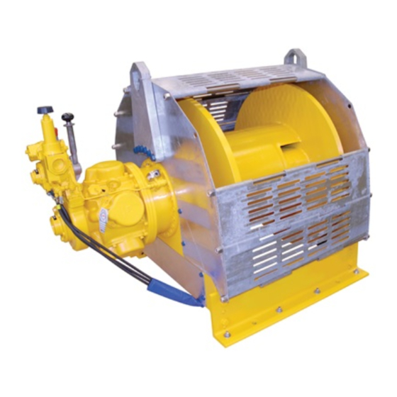
- Page 1 Product Information FORCE 5i Air Winch Models FA7i, FA7i-CE, FA7Ti, FA7Ti-CE, FA7Ti-GL, FA7Ti-GL-CE, FA7Ti-PL and FA7Ti-PL-CE (-CE compliant with European Directives) (Dwg. MHP2919) Save These Instructions Form MHD56438 Edition 3 October 2013 45899804 2013 Ingersoll-Rand ©...
-
Page 2: Product Description
Only allow trained technicians to perform maintenance on this product. For additional information contact factory or nearest Ingersoll Rand Ingersoll Rand Distributor. For additional supporting documentation refer to Table 1 ‘Product Information Manuals’ on page 2. Manuals can be downloaded from http://www.ingersollrandproducts.com. The use of other than genuine Ingersoll Rand replacement parts may result in safety hazards, decreased performance and increased maintenance and will invalidate all warranties. -
Page 3: Specifications
SPECIFICATIONS Model Code Explanation Example: FA7i-24MK320P FA7i Series (Capacity): FA7i 15,400 lbs (7 metric tons) FA7i/FA7Ti 10,200 lbs (4.6 metric tons) FA7Ti-GL 3,400 lbs (1.5 metric tons) Drum Flange Height: Standard flange Tall flange Guidline (42 inch drum) Podline (42 inch drum) Drum Length (Distance between drum flanges): Standard (Refer to Table 4 ‘Available Drum Lengths’... - Page 4 Table 2: Specifications Air System Rated Performance (at rated pressure/volume) Air Consumption Full Drum Full Drum Max Stall Maximum Force Models (at rated pressure Net Weight ** Rated Operating Line Pull Line Speed Pull, 1st Layer Freeboard Limit and load) Pressure Factor scfm cu.m/min...
-
Page 5: Installation
INSTALLATION Prior to installing the product, carefully inspect it for possible shipping damage. Table 7: Winch Bolt Hole Mounting Dimensions Products are supplied fully lubricated from the factory. Check oil levels and adjust Drum Length (inches) as necessary before operating product. Refer to “LUBRICATION” section Dimension on page 9 for recommended oils and lubrication intervals. - Page 6 Always ensure wire rope is correctly spooled and the first layer is tight against NOTICE drum. Always follow wire rope manufacturer’s recommendation on use and maintenance of wire rope. • When air filter is used ensure it allows air to pass through at products rated scfm.
-
Page 7: Operation
5. Check operation of brakes. Adjust if necessary as described in “MAINTENANCE” section in the Product Maintenance Information Manual. n Initial Winch Operating Checks 6. Check operation of limit switches, locking mechanisms and all safety devices when equipped. Winches are tested for proper operation prior to leaving the factory. Before the winch 7. -
Page 8: Frequent Inspection
2. Operate winch normally to position end of load line. Air pressure ported through brake housing overcomes spring pressure and moves 3. Connect load line to load. piston which releases brake. When control valve is placed in neutral position, air is vented, spring pressure overcomes air pressure and spring pressure moves piston, WARNING engages brake and prevents drum rotation. -
Page 9: Recommended Lubricants
2. Equipment which has been idle for a period of over six months shall be given a NOTICE complete inspection conforming with the requirements of ‘Periodic Inspection’ before being placed in service. Refer to Product Maintenance Information • The full extent of wire rope wear cannot be determined by visual inspection. Manual. - Page 10 The motor should be level-checked daily or at the start of each shift after any NOTICE accumulated water has been drained off. When motors are operated in temperatures below freezing, wait long enough at the end of shift for water to separate from oil but not long enough for it to freeze.
- Page 11 PRODUCT INFORMATION GRAPHICS Air Out Regulator DRUM Air In Lubricator (Dwg. MHP0133) Filter (Dwg. MHP0191) (Dwg. MHP2686) (Dwg. MHP2398) (Dwg. MHP2772) Fill Plug Drum Position Reduction Gear Assembly Level Plug Position Inboard Upright (Dwg. MHP2688) (Dwg. MHP0140) Form MHD56438 Edition 3...
- Page 12 PRODUCT INFORMATION GRAPHICS (CONTINUED) Lift Slider To Brake Handle UP to Unlock Haul-In Payout Threaded Air Inlet Port Ports 1-1/4 NPT Brake Release Port 1/4 NPT (Dwg. MHP2043) Exhaust Port 1-1/2 NPT (Dwg. MHP1809) “Emergency Stop” Button “ON” Button Function Levers Pendant Handle...
- Page 13 PRODUCT INFORMATION GRAPHICS (CONTINUED) Guideline/Podline Components Control Bracket and Valve View Rotated 180 (Dwg. MHP1348) Normal Position Guideline Position (Dwg. MHP1171) (Dwg. MHP1349) Form MHD56438 Edition 3...
-
Page 14: Service Notes
SERVICE NOTES Form MHD56438 Edition 3... - Page 15 DECLARATION OF CONFORMITY (CS) PROHLÁŠENÍ O SHODĚ (DA) OVERENSSTEMMELSESERKLÆRING (DE) KONFORMITÄTSERKLÄRUNG (EL) ∆ΗΛΩΣΗ ΑΝΑΓΝΩΡΙΣΗΣ (ES) DECLARACIÓN DE CONFORMIDAD (FI) VAKUUTUS NORMIEN TÄYTTÄMISESTÄ (FR) CERTIFICAT DE CONFORMITÉ (HU) MEGFELELŐSÉGI (IT) DICHIARAZIONE DI CONFORMITÀ (NL) SCHRIFTELIJKE NYILATKOZAT (LT) ATBILSTĪBAS DEKLARĀCIJA (LV) ATITIKTIES DEKLARACIJA VERKLARING VAN CONFORMITEIT (NO) KONFORMITETSERKLÆRING (PT) DECLARAÇÃO DE CONFORMIDADE (PL) DEKLARACJA ZGODNOŚCI (SK) PREHLÁSENIE O ZHODE (SL) IZJAVA O SKLADNOSTI...
- Page 16 www.ingersollrandproducts.com...
Need help?
Do you have a question about the FORCE FA7i and is the answer not in the manual?
Questions and answers