
Subscribe to Our Youtube Channel
Related Manuals for Ingersoll-Rand Force FH5i


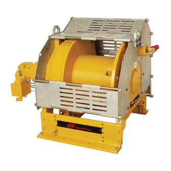
Summary of Contents for Ingersoll-Rand Force FH5i
- Page 1 Product Maintenance Information Models FH5i FH5Ti (Dwg. MHP2851) Save These Instructions Form MHD56358 Edition 1 November 2006 71477319 © 2006 Ingersoll Rand Company...
-
Page 2: Periodic Inspection
Only allow Ingersoll Rand trained technicians to perform maintenance on this product. For additional information contact Ingersoll Rand factory or nearest Distributor. For additional supporting documentation refer to Table 1 on page 2. Manuals can be downloaded from www.winchandhoistsolutions.com The use of other than genuine Ingersoll Rand replacement parts may result in safety hazards, decreased performance and increased maintenance and may invalidate all warranties. - Page 3 Table 3: Maintenance Interval Chart Normal Application The following work can be completed by owner maintenance personnel System Hydraulic Filter Inspect system hydraulic filter every 45 days or 125 hours. Grease Fittings Lubricate grease fittings every 180 days or 500 hours. Gearbox Oil Level Check oil level in gearbox every 180 days or 500 hours.
-
Page 4: Inspection Report
INSPECTION REPORT Ingersoll Rand Force 5 infinity Series Models FH5i or FH5Ti Hydraulic Winches Model Number: Date: Serial Number: Inspected by: Reason for Inspection: (Check Applicable Box) 1. Scheduled Periodic Inspection: (_____ Months _____ Years) Operating Environment: 2. Discrepancy(s) noted during Frequent Inspection Normal: ___ Heavy: ___ Severe: ___ 3. -
Page 5: Troubleshooting
TROUBLESHOOTING This section provides basic troubleshooting information. Determination of specific causes to problems are best identified by thorough inspections performed by personnel instructed in safety, operation and maintenance of this equipment. The chart below provides a brief guide to common winch symptoms, probable causes and remedies. SYMPTOM CAUSE REMEDY... - Page 6 Automatic Band Brake: SYMPTOM CAUSE REMEDY Brake cylinder will not release. Band brake out of adjustment. Adjust band brake to maintain correct cylinder stroke. Damaged cylinder seals. Replace or repair cylinder. Restricted return valve. Check return valve. Automatic Disc Brake: SYMPTOM CAUSE REMEDY...
- Page 7 3. Do not heat a part with a flame to free it for removal unless part being heated is Reservoir already worn or damaged beyond repair and no additional damage will occur to other parts. Maintain fluid level at all times. The fluid should be checked after the first 10 hours of initial operation.
-
Page 8: Cleaning, Inspection And Repair
Disconnect and remove hose and fittings from cylinder (110). 3. Remove capscrews (408) and washers (409) from both ends of shaft (403), and Remove cotter pin (102) and pin (101) from link stud (103) and brake band carefully slide shaft (403) through hole in upright (42). Press roller assembly (128). - Page 9 2. Install connecting link (125) on arm (124) and secure in position with pin Reduction Gear Assembly (121), washer (98) and cotter pin (102). Assemble connecting link (125) so NOTICE curved surface matches contour of brake band. 3. Install halves of brake band (128) to connecting link (125) and secure with pins •...
- Page 10 9. Lubricate and install ‘O’ ring (5) on seal adapter (10). Install oil seal (2) in seal adapter (10) ensuring seal lip will face into motor assembly. Testing 10. Install seal adapter assembly in brake adapter (6) bore. 11. Align holes in brake assembly with studs (7) and install brake assembly (20) on Operational Test brake adapter.
- Page 11 Table 4: Torque Chart Standard Coarse Thread Torque SAE Grade 5 SAE Grade 8 Size Lubricated PTFE Lubricated PTFE 1/4-20 8-10 12-14 9-10 5/16-18 17-20 13-15 25-28 18-21 11-13 3/8-16 31-35 23-26 14-16 44-49 33-37 20-22 7/16-14 49-56 37-42 22-25 70-79 52-59 31-36...
- Page 12 www.winchandhoistsolutions.com...
Need help?
Do you have a question about the Force FH5i and is the answer not in the manual?
Questions and answers