Table of Contents
Advertisement
Quick Links
Advertisement
Table of Contents

Subscribe to Our Youtube Channel
Related Manuals for Ingersoll-Rand FORCE 5i FA2.5i


Summary of Contents for Ingersoll-Rand FORCE 5i FA2.5i
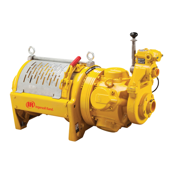
- Page 1 Product Information FORCE 5i Air Winch Models FA2.5i, FA2.5i-CE, FA5i, FA5i-CE, FA5Ti, and FA5Ti-CE (-CE compliant with European Directives) (Dwg. MHP2669) Save These Instructions Form MHD56434 Edition 6 October 2015 45899762 2015 Ingersoll Rand ©...
-
Page 2: Product Description
Only allow trained technicians to perform maintenance on this product. For additional information contact factory or nearest Ingersoll Rand Ingersoll Rand Distributor. For additional supporting documentation refer to Table 1 ‘Product Information Manuals’ on page 2. Manuals can be downloaded from ingersollrandproducts.com The use of other than genuine Ingersoll Rand replacement parts may result in safety hazards, decreased performance and increased maintenance and will invalidate all warranties. -
Page 3: Specifications
SPECIFICATIONS Model Code Explanation Example: FA5i-24MK1P FA5i Series (Capacity): FA2.5i 5,000 lbs (2.5 metric ton) FA5i 11,000 lbs (5 metric ton) FA5Ti 8,400 lbs (4 metric ton) Drum Flange Height: Standard flange Tall flange Drum Length (Distance between drum flanges): Standard (Refer to Table 4 ‘Available Drum Lengths’... -
Page 4: Installation
Table 2: Specifications Air System Rated Performance (at rated pressure/volume) Air Consumption Full Drum Full Drum Mid Drum Max Stall Pull Maximum Rated Force Models (at rated pressure Line Pull Line Speed Line Speed 1st Layer Freeboard Weight ** Operating Limit and load) Pressure... - Page 5 When considering wire rope requirements the actual working load must include not WARNING only the static or dead load but also loads resulting from acceleration, retardation and shock load. Consideration must also be given to the size of the winch wire rope •...
- Page 6 n Air Supply n Tensioning System (optional feature) The air supply must be clean, free from moisture and lubricated to ensure optimum Refer to Dwg. MHP1176 on page 12; A. Payout; B. Motor; C. Haul-In; D. Brake; E. motor performance. Foreign particles, moisture and lack of lubrication are the Check Valve;...
-
Page 7: Operation
Table 8: Winch Bolt Hole Mounting Dimensions - Refer to Dwg. MHP0133 on page 11; A. Drum. Drum Length (inches) Models Dimension inch “A” inch “B” * FA2.5i inch Note 3 “B” ** (Note 1) inch 0.6875 “C” 17.5 Bolt Hole Qty each Siderail inch 31.25... - Page 8 Automatic Drum Band Brake NOTICE The automatic drum band brake is a spring applied, air released brake which utilizes • If winch overload occurs, overload device, if equipped, also stops winch. To an air actuated, spring loaded cylinder, that automatically disengages brake when operate winch after an overload, reduce load and reset overload.
-
Page 9: Frequent Inspection
Careful inspection on a regular basis will reveal potentially dangerous conditions 11. Wire Rope Spooling. Visually check reeving and ensure wire rope feeds on and while still in the early stages, allowing corrective action to be taken before the off the drum smoothly. Verify spooling direction (overwind or underwind) is condition becomes dangerous. -
Page 10: Recommended Lubricants
WARNING CAUTION • Pneumatic products use oil to prevent excessive heat buildup and to • Do not over fill. Excess oil will reduce operating efficiency and increase oil prevent wear that could cause sparks. Oil levels must be properly temperature. maintained. - Page 11 PRODUCT INFORMATION GRAPHICS Lift Slider Handle UP to Unlock DRUM Haul-In Payout Air Inlet Port 1-1/4 NPT (Dwg. MHP0133) Brake Release Port 1/4 NPT Exhaust Port 1-1/2 NPT (Dwg. MHP1809) (Dwg. MHP2686) Air Out Regulator Air In Lubricator Filter (Dwg. MHP2619) (Dwg.
- Page 12 PRODUCT INFORMATION GRAPHICS (CONTINUED) Fill Cap Vent Cap Level Plug Drain Plug (Dwg. MHP2126) (Dwg. MHP1176) Fill Plug Drum Regulator Position Reduction Gear Assembly Auxiliary Valve Pressure (shown in Normal Gauge Position) Level Plug Position Inboard Upright Control Valve (Dwg. MHP0140) (Dwg.
- Page 13 PRODUCT INFORMATION GRAPHICS (CONTINUED) To Brake Threaded Ports (Dwg. MHP2688) (Dwg. MHP2043) (Dwg. MHP2772) (Dwg. MHP2398) “Emergency Stop” Button “ON” Button Function Levers Pendant Handle (Dwg. MHP1892) Form MHD56434 Edition 6...
-
Page 14: Service Notes
SERVICE NOTES Form MHD56434 Edition 6... - Page 15 DECLARATION OF CONFORMITY (CS) PROHLÁŠENÍ O SHODĚ (DA) OVERENSSTEMMELSESERKLÆRING (DE) KONFORMITÄTSERKLÄRUNG (EL) ∆ΗΛΩΣΗ ΑΝΑΓΝΩΡΙΣΗΣ (ES) DECLARACIÓN DE CONFORMIDAD (FI) VAKUUTUS NORMIEN TÄYTTÄMISESTÄ (FR) CERTIFICAT DE CONFORMITÉ (HU) MEGFELELŐSÉGI NYILATKOZAT (IT) DICHIARAZIONE DI CONFORMITÀ (LT) ATBILSTĪBAS DEKLARĀCIJA (LV) ATITIKTIES DEKLARACIJA (NL) SCHRIFTELIJKE VERKLARING VAN CONFORMITEIT (NO) KONFORMITETSERKLÆRING (PT) DECLARAÇÃO DE CONFORMIDADE (PL) DEKLARACJA ZGODNOŚCI (SK) PREHLÁSENIE O ZHODE (SL) IZJAVA O SKLADNOSTI (SV) FÖRSÄKRAN OM ÖVERENSSTÄMMELSE Ingersoll Rand...
- Page 16 ingersollrandproducts.com...
Need help?
Do you have a question about the FORCE 5i FA2.5i and is the answer not in the manual?
Questions and answers