
Subscribe to Our Youtube Channel
Related Manuals for Digitus DN-651146


Summary of Contents for Digitus DN-651146
- Page 1 8-Port 10/100Base-TX to 100Base-FX Industrial Ethernet (PoE) Switch Quick Installation Guide DN-651132 & DN-651133 DN-651146 & DN-651147...
-
Page 2: Table Of Contents
Table of content Overview ..................2 Features ..................3 Specification ................3 Packages ..................6 Switch Panel ................7 Interface Definition ..............8 LED Indicator ................10 Installation caution ..............10 1. Overview Industrial Ethernet switch with 8-Port 10/100Mbps RJ45 + 100Mbps / 1000Mbps base-FX, the Product meet CE, RoHS standards. -
Page 3: Features
In line with industrial operating standards, the average trouble-free work in more than 300,000 hours Working power supply: DN-651132/DN-651146: DC 12-48V DN-651133/DN-651147 (PoE): DC 48-57V Lightning Surge Protection (Power): 5000A (8/20μs) 3. Specification 3.1 Standard:... - Page 4 3.6 Mechanical characteristic: IP40 aluminum housing DIN rail install Natural cooling, no fan 3.7 Industrial standard: FCC Part 15 Subpart B, EN55032, Class A IEC61000-4-2 (ESD): ±8kV (contact), ±12kV (air) IEC61000-4-3 (RS): 10V/m (80~1000MHz) IEC61000-4-4 (EFT): Power Port: ±4kV; Data Port: ±2kV IEC61000-4-5 (Surge): Power Port: ±2kV/DM, ±4kV/CM;...
- Page 5 3.8 Spec table: Model No DN-651132 DN-651133 Network port 8x 100Mbps 8x 100Mbps SFP slot 1x 100Mbps 1x 100Mbps IEEE802.3af/ PoE Spec. IEEE802.3at Power Pin 1/2+;3/6- Assignment Bandwidth 1.8G 1.8G Packet Buffer 1.25Mbit 1.25Mbit Memory Forwarding rate 1.4Mpps 1.4Mpps Mac address table Max.
-
Page 6: Packages
Model No DN-651146 DN-651147 Network port 8x 100Mbps 8x 100Mbps SFP slot 2x 1000Mpbs 2x 1000Mpbs IEEE802.3af/ PoE Spec. IEEE802.3at Power Pin 1/2+;3/6- Assignment Bandwidth 5.6Gbps 5.6Gbps Packet Buffer 1.2Mbit 1.2Mbit Memory Forwarding rate 4.2Mpps 4.2Mpps Mac address table Max. Frame Size... -
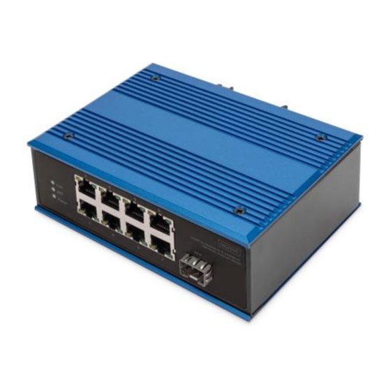
Page 7: Switch Panel
5. Switch Panel Side panel: P1 and P2 are the number of connecting terminals, P+1 and P-1 are respectively to the positive and negative poles to be connected; Earthing screw, used for Earthing equipment. Front panel: The orange light on the port is the LINK light, which is on when the connection is established and the data transmission is flashing. -
Page 8: Interface Definition
Switch size (mm) 6. Interface Definition 6.1 10/100Base-TX Ethernet interface: This series of switches provides MDI/MDI-X self-identification with cable support on all 10/100Basc-TX ports. In use, the Ethernet port of the switch can be connected with other Ethernet terminal devices through network cables (direct or cross). - Page 9 For the MDI-X port of a switch or hub, cross lines are used: 1-3, 2-6, 3-1, 6-2, 4-7, 5-8, 7-4, 8-5.10Base-T/100Base-T (X) pins are defined as follows: Pin No. MDI signal MDI-X signal 4,5,7,8 Note: "Tx ±" refers to send data ±, "Rx ±" refers to received data ±, and "-"...
-
Page 10: Led Indicator
7. LED Indicator LED indicator Status Definition Power supplying in Red LED on normal Power Power supply abnormal Red LED off or no powering Network connection in Yellow LED on normal Link communication in Yellow LED flashing RJ45 indicator normal Green LED on PoE feeding in normal Yellow/Green LED off... - Page 11 8.2 Din rail installation: The first step is to check the grounding and stability of the guide rail: the guide rail slot of the switch is clamped into the guide rail; The second step: from the center to both sides of the guide rail positioning screws in order.
- Page 12 This is a Class A product. In home environment, this product may cause radio interference. In this case, the user may be required to take appropriate measures. Hereby Assmann Electronic GmbH, declares that the Declaration of Conformity is part of the shipping content. If the Declaration of Conformity is missing, you can request it by post under the below mentioned manufacturer address.
Need help?
Do you have a question about the DN-651146 and is the answer not in the manual?
Questions and answers