
Subscribe to Our Youtube Channel
Related Manuals for Digitus DN-651138


Summary of Contents for Digitus DN-651138
- Page 1 16-port 10/100/1000Base-TX +2x Gigabit SFP Industrial Ethernet Switch Quick Installation Guide DN-651138...
-
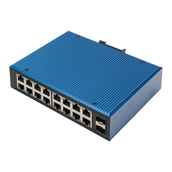
Page 2: Switch Panel
Industrial Ethernet switch with 16-Port 10/100/1000Mbps Base-TX and 2-Port Gigabit SFP, the Product meet CE, FCC, RoHS standards. DN-651138 switch has the operating temperature of -40°C ~ 80°C, has the super firmness can adapt to all kinds of harsh environment, can also be conveniently placed in the compact space of the control box. - Page 3 The green LED is POE light, which is only on when the switch port is supplying power to PD device (this model is not to support PoE); Power indicator light is on when connecting with Power. Switch size (mm) 3. Features Support long range transmission by fiber optical port.
-
Page 4: Specification
4. Specification 4.1 Standard: IEEE802.310Base-T; IEEE802.3i 10Base-T; IEEE802.3u 100Base-TX/FX; IEEE802.3ab 1000Base-T; IEEE802.3z 1000Base-X; IEEE802.3x 4.2 Interface: 16-Port RJ45; 2- Port SFP Uplink 4.3 Work environment: Working: -40 ~ 80 °C Storage: -40 ~ 80 °C Relative Humidity: 5%~95 % (No condensation) 4. -
Page 5: Interface Definition
4.7 Industrial standard: FCC Part 15 Subpart B, EN55032, Class A IEC61000-4-2 (ESD): ±8kV (contact), ±12kV (air) IEC61000-4-3 (RS): 10V/m (80~1000MHz) IEC61000-4-4 (EFT): Power Port: ±4kV; Data Port: ±2kV IEC61000-4-5 (Surge): Power Port: ±2kV/DM, ±4kV/CM; Data Port: ±2kV IEC61000-4-6 (CS): 3V (10 kHz-150 kHz); 10V (150 kHz-80MHz) IEC61000-4-16 (Common mode conduction): 30V (cont.), 300V (1s) Frequency range: 150kHz-80MHz Impact: IEC60068-2-27... - Page 6 For the MDI-X port of a switch or hub, cross lines are used: 1-3, 2-6, 3-1, 6-2, 4-7, 5-8, 7-4, 8-5.10Base-T/100Base-T (X) pins are defined as follows: Pin No. MDI signal MDI-X signal 4,5,7,8 Note: "Tx ±" refers to send data, "Rx ±" refers to received data ±, and "-"...
- Page 7 5.2.2 SFP module (Optional, not included) LC connector, Gigabit, 20km Single mode, dual fiber (DN-81011) LC connector, Gigabit, 20km Single mode, Single fiber (DN-81020 and DN-81021)
-
Page 8: Installation Caution
6. LED Indicator LED indicator Status Definition Power supplying in Red LED on normal P1/P2 Power supply abnormal Red LED off or no powering Network connection in Yellow LED on normal RJ45 indicator Link communication in Yellow LED flashing normal Yellow/Green LED off No connection at port Note: this model is not available with PoE... - Page 9 7.2 Din rail installation: The first step is to check the grounding and stability of the guide rail: the guide rail slot of the switch is clamped into the guide rail; The second step: from the center to both sides of the guide rail positioning screws in order.
- Page 10 8. Packages Content Industrial switch 1 PCS Quick installation guide 1 PCS Rackmount kit 1 SET Terminal block 1 PCS This is a Class A product. In home environment, this product may cause radio interference. In this case, the user may be required to take appropriate measures.
Need help?
Do you have a question about the DN-651138 and is the answer not in the manual?
Questions and answers