
Related Manuals for Digitus DN-651109


Summary of Contents for Digitus DN-651109
- Page 1 Industrial 4‐port Gigabit PoE+ Switch with 2 x SFP uplink ‐ DN‐651109 Industrial 8‐port Gigabit PoE+ Switch with 2 x SFP uplink ‐ DN‐651110 User Manual DN‐651109 / DN‐651110 ...
-
Page 2: Package Contents
If any part is lost and damaged, please contact your local agent immediately. Introduction The DIGITUS® Industrial Gigiabit PoE Switch is designed for harsh environments where it is exposed to moisture, temperature fluctuations and vibration. With a temperature range of ‐40°C to 75°C, the Industrial Gigabit PoE Switch can be used under the most adverse conditions. The PoE ports with IEEE802.3af/at support can supply PoE capable devices with up to 30 W per port. It ensures a constant ... -
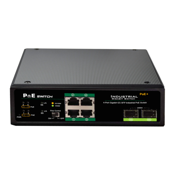
Page 3: Hardware Description
Hardware Description Front Panel The Front Panel Consists of Ethernet Ports. The LED indicators are also located on the panel. DN‐651109 DN‐651110 DIP Switch The DIP switch located on the panel. Flow Control ON: prevents data loose from mass data transmission and slow down the network speed. It is suitable for network environment where the network is shared to public. ... -
Page 4: Led Indicator
LED indicator LED Color Function Off: No Power supply PWR Green Light: Indicates the switch has power Off: No device is connected to the corresponding port Light: Indicates the link through that port is Green successfully established at 1000Mbps Blink: Indicates that the Switch is actively sending or receiving data over that port LNK/ACT Off: No device is connected to the corresponding port Light: Indicates the link through that port is Orange successfully established at 10/100Mbps Blink: Indicates that the Switch is actively sending or receiving data over that port Off: No PoE powered device (PD) connected PoE Orange Light: There is a PoE PD connected to be port Blink: Indicates port abnormal PoE function ... -
Page 5: Upper Panel
Upper Panel The upper panel has a standard 5‐Pin industrial power input terminal for double redundant power backup and accepts DC power input. Power input This unit provides a 5‐pin terminal block. It can be operated using 48‐57 V DC power source. Always make sure your input voltage is within this supported voltage range. To connect power: This unit supports two power inputs. Follow the printed polarity for +V1‐, +V2‐ and ground. Connect positive wires to V+, connect negative wires to V‐, and connect a neutral wire to the ground mark. +V1‐ is for power input one connection (PWR1). +V2‐ is for power input two connection (PWR2). Figure: ... -
Page 6: Installation Of The Switch
WARNING: Always SHUT OFF power source to connect power wire. WARNING: Any exceeded input voltage will not make this unit function and may damage this unit. Grounding column The switch already comes with lightning protection mechanism. You can also ground the switch through the PE (Protecting Earth) with Ground Cable. Installation of the Switch This part describes how to install your Ethernet Switch and make connections to it. Please follow the following instructions to avoid incorrect installation causing device damage and security threat. Before cleaning the switch, unplug the power plug of the switch first. Do not clean the switch with wet cloth or liquid; Do not place the switch near water or any damp area. Prevent water or moisture from entering the switch chassis; Do not place the switch on an unstable case or desk. The switch might be damaged severely in case of a fall; Ensure proper ventilation of the equipment room and keep the ventilation vents of the switch free of obstruction; ... -
Page 7: Din-Rail Mounting
DIN‐Rail Mounting The DIN‐Rail is already screwed on the Industrial Equipment. Please refer to following figures and know how to hang the Industrial Equipment: Step 1: Lightly press the button of DIN‐Rail into the track. Install Industrial Equipment in DIN‐Rail mount. Step 2: Check the DIN‐Rail is tightly on the track. ... - Page 8 Remove DIN‐Rail Mounting Step 1: Please refer to following procedures to remove the Industrial Equipment from the track . Remove Industrial Equipment in DIN‐Rail mount. Step 2: Lightly press the button of DIN‐Rail for remove it from the track. ...
-
Page 9: Specifications
Specifications Industrial 4‐Port Gigabit Industrial 8‐port Gigabit Model PoE+ Switch with 2 x SFP PoE+ Switch with 2 x SFP Uplink uplink IEEE802.3, IEEE802.3u, IEEE802.3az, IEEE802.3x, Standard IEEE802.3af, IEEE802.3at, IEEE 802.3ab, IEEE 802.3z 10BASE‐T: UTP category 3,4,5 cable (≤100m) 100BASE‐TX: UTP category 5 cable (≤100m) 1000BASE‐T: UTP category 5e, 5 cable (≤100m) Network 1000BASE‐TX : Gigabit SFP optical RJ45 electrical module Media(Cable) 1000BASE‐SX : Gigabit SFP multimode (850nm, LC, DDM) 1000BASE‐LX : Gigabit SFP mode (1310nm, LC, DDM) 1000BASE‐ZX: Gigabit SFP single mode (1550nm, LC, DDM) MAC Address Table 4K, Auto‐learning, Auto‐aging Transfer mode Store‐and‐Forward Jumbo frame 9216 Byte Packet buffer 1.5M bit Switching Capacity 12Gbps 20Gbps Packet Forward Speed 8.9Mpps 14.88Mpps Input power supply DC:48‐57V ... - Page 10 This is a Class A product. In home environment, this product may cause radio interference. In this case, the user may be required to take appropriate measures. Hereby Assmann Electronic GmbH, declares that the Declaration of Conformity is part of the shipping content. If the Declaration of Conformity is missing, you can request it by post under the below mentioned manufacturer address. www.assmann.com Assmann Electronic GmbH Auf dem Schüffel 3 58513 Lüdenscheid Germany ...
Need help?
Do you have a question about the DN-651109 and is the answer not in the manual?
Questions and answers