Table of Contents
Advertisement
Quick Links
Instructions
Packaged condensing unit
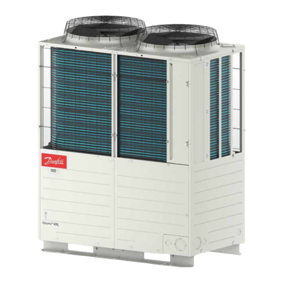
Optyma™ iCO2 (Transcritical/Inverter)
Universal application
Fig. 1 OP-UPAC015COP04E
© Danfoss | Climate Solutions | 2023.02 | LCA012A024
1 - Introduction ............................................................................................. 6
2 - Handling and storage ........................................................................... 7
3 - Installation precautions ....................................................................... 7
4 - Installation ................................................................................................ 9
5 - Pressure test ...........................................................................................12
6 - Vacuum dehydration ...........................................................................13
7 - Electrical connections .........................................................................21
8 - Filling the system ..................................................................................23
9 - Setting the electronic controller .....................................................24
10 - Procedure and caution for commissioning ..............................35
11 - Operation ..............................................................................................38
12 - Check with running unit ..................................................................39
13 - Guidance at delivery .........................................................................39
14 - Maintenance ........................................................................................39
15 - Declaration of incorporation ........................................................43
16 - Warranty .................................................................................................44
17 - Disposal .................................................................................................45
18 - Servicing ..............................................................................................45
Annex A - Technical data ............................................................... 48
Annex B - PID and GA ..................................................................... 50
Annex C - Wiring diagram ............................................................. 54
Annex D - Outline of installation ................................................. 56
Annex E - Outline of refrigerant ................................................... 57
Annex F - Check list ........................................................................ 58
118A5495A - AN405821998738en-000102 | 1
Advertisement
Table of Contents

Related Manuals for Danfoss Optyma iCO2


Summary of Contents for Danfoss Optyma iCO2
-
Page 1: Table Of Contents
Annex D - Outline of installation ..........56 Fig. 1 OP-UPAC015COP04E Annex E - Outline of refrigerant ........... 57 Annex F - Check list ................ 58 118A5495A - AN405821998738en-000102 | 1 © Danfoss | Climate Solutions | 2023.02 | LCA012A024... - Page 2 When using a burner, take care not to burn nearby parts, oil return pipe, or sound insulation cover. If the oil return cover is burned, oil under high pressure will burst out, causing fire, or injury. 118A5495A - AN405821998738en-000102 | 2 © Danfoss | Climate Solutions | 2023.02 | LCA012A024...
- Page 3 Use a circuit breaker with the contact gap of category 3, or higher, at the source power supply. Shield communication cables used for communication with and remote monitoring of the indoor unit. © Danfoss | Climate Solutions | 2023.02 | LCA012A024 118A5495A - AN405821998738en-000102 | 3...
- Page 4 Do not mount or place something on the condensing unit. It could cause injury if you fall, damage the machine, or drop the object. CAUTION Refrain from touching hands on the gas cooler fin directly. You could get hurt. 4 | AN405821998738en-000102 - 118A5495A © Danfoss | Climate Solutions | 2023.02 | LCA012A024...
- Page 5 Oil is retained at the high pressure side of scroll-rotary compressor. WARNING Care must be taken particularly when charging or discharging oil during maintenance, service, or test run. © Danfoss | Climate Solutions | 2023.02 | LCA012A024 118A5495A - AN405821998738en-000102 | 5...
-
Page 6: Introduction
• Pass the power supply cable through a metal pipe. Make sure to ground the pipe. • Ground the refrigerating machine and the receiving devices individually and independently. 6 | AN405821998738en-000102 - 118A5495A © Danfoss | Climate Solutions | 2023.02 | LCA012A024... -
Page 7: Handling And Storage
(*) Be sure to keep more than 100mm Service space spaces when the unit contacts with a wall. If the unit installed in succession, 10mm gust. spaces is enough. Fig. 3 © Danfoss | Climate Solutions | 2023.02 | LCA012A024 118A5495A - AN405821998738en-000102 | 7... - Page 8 Instructions • The installation in which the condensing unit is installed must comply to Pressure Equipment Directive (PED) no. 2014/68/EU. The Optyma iCO2 condensing unit assembly (partially completed assembly) certified for PED by Notified body (Vincotte - notification number 0026).
-
Page 9: Installation
50% of refrigeration unit’s rated capacity. Module controller Use specific module controllers and expansion valves recommended by Danfoss Select an appropriate diameter for electronic expansion valve. Expansion valve Recommended (Example) ... When 3 units of low pressure side devices are connected: AKV 10P4... - Page 10 1. Install the outdoor unit on a stand that is higher than expected surface of snow. 2. Install the unit under the eaves, or a snow roof (provided at site). 10 | AN405821998738en-000102 - 118A5495A © Danfoss | Climate Solutions | 2023.02 | LCA012A024...
- Page 11 Vacuum dry (2nd). iv. Ultimate vacuum must be maintained at -1 bar after letting it alone. If it is not, repeat the Reducer vacuum dry and vacuum break. © Danfoss | Climate Solutions | 2023.02 | LCA012A024 118A5495A - AN405821998738en-000102 | 11...
-
Page 12: Pressure Test
When venting the gas, start from the low pressure side. (Take care not to make the low pressure side of compressor higher than the high pressure side.) 12 | AN405821998738en-000102 - 118A5495A © Danfoss | Climate Solutions | 2023.02 | LCA012A024... -
Page 13: Vacuum Dehydration
• Time of oil level low with OLS1-2 during compressor running can be summed and checked with 7-segment display “C42”, which displays “Accumulated time of CM1 ON and OLS1-2 OFF”. © Danfoss | Climate Solutions | 2023.02 | LCA012A024 118A5495A - AN405821998738en-000102 | 13... - Page 14 Farthest equipment in group b First branch φ9.52 φ9.52 φ12.7 φ15.88 φ15.88 φ19.05 Group c Farthest equipment in group c φ9.52 φ9.52 φ12.7 φ15.88 Fig. 16 14 | AN405821998738en-000102 - 118A5495A © Danfoss | Climate Solutions | 2023.02 | LCA012A024...
- Page 15 Φ19.05 equivalent pipe length = Piping refrigerating oil quantity(cc)/16(cc/m) 4,800 4380cc 4,300 3,800 3430cc 3,300 2780cc 2,800 2,300 1830cc 1,800 100m Equivalent pipe length (m) Standard oil quantity Maximum oil quantity Fig. 17 © Danfoss | Climate Solutions | 2023.02 | LCA012A024 118A5495A - AN405821998738en-000102 | 15...
- Page 16 6. Please note that a special device (manual pump) is required when condensing unit oil is charged after operating the unit, 7. Dispose of the condensing unit oil and container after opening according to the regulations of each country. 16 | AN405821998738en-000102 - 118A5495A © Danfoss | Climate Solutions | 2023.02 | LCA012A024...
- Page 17 (3).1 Standard refrigerant quantity of condensing unit Standard refrigerant quantity of condensing unit (kg) Evaporation temperature setting ≤ -5°C Evaporation temperature setting > -5°C 10.2 12.2 © Danfoss | Climate Solutions | 2023.02 | LCA012A024 118A5495A - AN405821998738en-000102 | 17...
- Page 18 Piping refrigerant quantity = 0.098 (kg/m) x 10 (m) + 0.054 (kg/m) + (10 (m) + 10 (m)) + 0.025 (kg/m) x (5 (m) + 5 (m)) = 2.3 kg………………… (a) 18 | AN405821998738en-000102 - 118A5495A © Danfoss | Climate Solutions | 2023.02 | LCA012A024...
- Page 19 Overcharge of refrigerant could cause the liquid back from the medium pressure receiver. While the condensing unit is operating, take care to avoid the degree of superheat of under-dome (under-dome temperature - saturation temperature of medium pressure sensor) becomes lower than 10 deg. © Danfoss | Climate Solutions | 2023.02 | LCA012A024 118A5495A - AN405821998738en-000102 | 19...
- Page 20 5. Even when the charge pressure dropped in the cylinder, never heat the cylinder higher than 40°C for reason of security. 6. Do not lay flat the cylinder during charging. 20 | AN405821998738en-000102 - 118A5495A © Danfoss | Climate Solutions | 2023.02 | LCA012A024...
-
Page 21: Electrical Connections
When tightening electric wires and operation circuit wires to the terminal block, tighten the screws at torques as shown in the table at right. Screw size Tightening torque (Nm) 1.0 ~ 1.3 2.0 ~ 2.5 4.0 ~ 5.0 9.0 ~ 11.0 18.0 ~ 23.0 © Danfoss | Climate Solutions | 2023.02 | LCA012A024 118A5495A - AN405821998738en-000102 | 21... - Page 22 • Communication method is based on RS485. • Connect signal cable to A, B on the terminal board. • Signal cables has the polarity. Connect them as shown in fig. 24. 22 | AN405821998738en-000102 - 118A5495A © Danfoss | Climate Solutions | 2023.02 | LCA012A024...
-
Page 23: Filling The System
• The remaining charge is done until the installation has reached a level of stable nominal condition during operation. • Never leave the filling cylinder connected to the circuit. © Danfoss | Climate Solutions | 2023.02 | LCA012A024 118A5495A - AN405821998738en-000102 | 23... -
Page 24: Setting The Electronic Controller
Once it reverts, as a result of control, to a state that it can operate within the allowable range, the control function is released and it returns to ordinary operation. 24 | AN405821998738en-000102 - 118A5495A © Danfoss | Climate Solutions | 2023.02 | LCA012A024... - Page 25 5. Display change : Special display shows other than CXX, PXX and FXX. If specialdisplay occurs. [CXX] Special display Button operation Special display No operation for 10 sec.* release Auto feed Button operation Fig. 26 © Danfoss | Climate Solutions | 2023.02 | LCA012A024 118A5495A - AN405821998738en-000102 | 25...
- Page 26 External input 1: Short) 1's place: CNS3 (*2) 100's place: 52X1 0, 1 Relay output (0: Open 10's place: 52X2 (Spare) 1: Short) 1's place: (Spare) 26 | AN405821998738en-000102 - 118A5495A © Danfoss | Climate Solutions | 2023.02 | LCA012A024...
- Page 27 Cause of compressor error detection 3 0~127 operation. This is retained in EEPROM memory till the cause of compressor stop by first error occurs after turning power on. © Danfoss | Climate Solutions | 2023.02 | LCA012A024 118A5495A - AN405821998738en-000102 | 27...
- Page 28 20: (Default) EEVSC target superheat degree change value 1 – 40 (0.5 – 20 deg) 0: (Default) EEV-LB target discharge pipe temp. change -20 – 20 deg 28 | AN405821998738en-000102 - 118A5495A © Danfoss | Climate Solutions | 2023.02 | LCA012A024...
- Page 29 Medium pressure sensor broken wire (PSM) Continuous Once Medium pressure sensor output error Continuous Once External input error stop Continuous Once E88-1 Oil level error (CM1) Continuous Once CPU-CPU communication error © Danfoss | Climate Solutions | 2023.02 | LCA012A024 118A5495A - AN405821998738en-000102 | 29...
- Page 30 Module controller code “r28” is set to 0, PsD is the value +1.0bar from value set with rotary SW of the condensing unit and PsU is the value -1.0bar from value set with rotary SW of the condensing unit. 30 | AN405821998738en-000102 - 118A5495A © Danfoss | Climate Solutions | 2023.02 | LCA012A024...
- Page 31 • Medium pressure receiver inlet electronic expansion valve OFF (full open) Compressor error stop • Gas cooler fan OFF after delay 3 min. delay time elapsed? Fig. 27 © Danfoss | Climate Solutions | 2023.02 | LCA012A024 118A5495A - AN405821998738en-000102 | 31...
- Page 32 • When the discharge gas temperature (Td) rises to 150°C even if this control is turned on, the condensing unit is stopped with the retry stop. If the retry stop repeats 5 times, however, the machine is stopped with the error stop. (Alarm code “E36” is displayed.) 32 | AN405821998738en-000102 - 118A5495A © Danfoss | Climate Solutions | 2023.02 | LCA012A024...
- Page 33 • After restart, if the compressor is running and the oil level switch (OLS 1-2) detects "no oil" for 30 seconds in a row, an insufficient amount of oil is output. After restart, if the compressor is running and the oil level switch (OLS 1-2) detects "oil present" for 30 seconds continuously, reset it. © Danfoss | Climate Solutions | 2023.02 | LCA012A024 118A5495A - AN405821998738en-000102 | 33...
- Page 34 EEV-LB1 temperature. EEV for liquid bypass Initial speed 40 rps Compressor speed Ordinary control 0 rps 3 min. 0 rps 105 sec Fig. 33 34 | AN405821998738en-000102 - 118A5495A © Danfoss | Climate Solutions | 2023.02 | LCA012A024...
-
Page 35: Procedure And Caution For Commissioning
6. Turn on the source power supply 6 hours or more before starting the compressor to energize the crankcase without turning on the operation switch (CNS2). 7 segment display Operation switch(CNS2) Bracket Carton Carton Fig. 34 © Danfoss | Climate Solutions | 2023.02 | LCA012A024 118A5495A - AN405821998738en-000102 | 35... - Page 36 The low pressure setting at the shipment is "SW1"="0", "SW2"="0" A guide for setting of pressure value is shown below. *1 The evaporation temperature means the saturated temperature of suction pressure. 36 | AN405821998738en-000102 - 118A5495A © Danfoss | Climate Solutions | 2023.02 | LCA012A024...
- Page 37 25.47 bar Down Pressure equivalent to “Evaporation temperature (setting value) -10 °C” 21.89 bar Fig. 38 Pressure equivalent to “Evaporation temperature (setting value) -15 °C” 18.68 bar © Danfoss | Climate Solutions | 2023.02 | LCA012A024 118A5495A - AN405821998738en-000102 | 37...
-
Page 38: Operation
When the external input harness is inserted into the external input “CN3 ” of the control board while the compressor is in operation and the rotational speed is less than 70 rps, the oil return control is immediately executed. 38 | AN405821998738en-000102 - 118A5495A © Danfoss | Climate Solutions | 2023.02 | LCA012A024... -
Page 39: Check With Running Unit
• Check that all electrical connections are still adequately fastened. • Keep the unit clean and verify the absence of rust and oxidation on the unit components, tubes and electrical connections. © Danfoss | Climate Solutions | 2023.02 | LCA012A024 118A5495A - AN405821998738en-000102 | 39... - Page 40 • When the cause of failure is unknown, check the model of condensing unit, production No. and condition of failure, and report them to specified service company. 40 | AN405821998738en-000102 - 118A5495A © Danfoss | Climate Solutions | 2023.02 | LCA012A024...
- Page 41 2: Quiet mode input 3: Error reset 4: Compulsory oil return input CNG2 9:(Default) 0~20 5: Gas cooler fan snow control input 9: Multistage demand input © Danfoss | Climate Solutions | 2023.02 | LCA012A024 118A5495A - AN405821998738en-000102 | 41...
- Page 42 Connect the adequate low pressure devices pressure devices Defect the anomalous under dome E43-1 Liquid return error temp. Under dome temp. sensor, connector Replace disconnection or short-circuit 42 | AN405821998738en-000102 - 118A5495A © Danfoss | Climate Solutions | 2023.02 | LCA012A024...
-
Page 43: Declaration Of Incorporation
• Condensing unit measurements are made according to standard “EN 13771-2:2017” – Compressor and condensing units for refrigeration-performance testing and test methods- part 2: Condensing units. © Danfoss | Climate Solutions | 2023.02 | LCA012A024 118A5495A - AN405821998738en-000102 | 43... -
Page 44: Warranty
• Compressor opened or returned unsealed. • Rust, water or leak detection dye inside the compressor. • Use of a refrigerant or lubricant not approved by Danfoss. • Any deviation from recommended instructions pertaining to installation, application or maintenance. • Use in mobile applications. -
Page 45: Disposal
17 – Disposal Danfoss recommends that condensing units and oil should be recycled by a suitable company at its site. When the condensing unit is relocated and reinstalled after moving to new address, or other, specialized techniques are required. Consult your dealer or specified contact desk of maker. - Page 46 *1 Demand input: P04 *2 Demand rate setting for multistage demand input: 0%, 40%, 60%, 80% PF22: OFF → 000 → 040 → 060 → 080, P14, P15 46 | AN405821998738en-000102 - 118A5495A © Danfoss | Climate Solutions | 2023.02 | LCA012A024...
- Page 47 Spare (Spare setting to be same as default setting.) Fan ON output Spare (Spare setting to be same as default setting.) Oil return operation output Spare (Spare setting to be same as default setting.) © Danfoss | Climate Solutions | 2023.02 | LCA012A024 118A5495A - AN405821998738en-000102 | 47...
-
Page 48: Annex A - Technical Data
10mm spaces is enough. (*2) A space of 330mm is necessary when the power cable is taken in from L2 side, where units are installed in series. 48 | AN405821998738en-000102 - 118A5495A © Danfoss | Climate Solutions | 2023.02 | LCA012A024... - Page 49 Adjustable time delay (Compressor) Yes (available in Controller) Electronic Expansion Valve Solenoid valve Receiver Service valves Accumulator Oil separator Subcooling coil Pressure relief valve Stop valve Check Valve © Danfoss | Climate Solutions | 2023.02 | LCA012A024 118A5495A - AN405821998738en-000102 | 49...
-
Page 50: Annex B - Pid And Ga
(*) Stated as the rated output of compressor motor Rated speed at freezing or refrigeration, whichever is larger, is taken. OP-UPAC015COP04E … Rated speed 104 rps 50 | AN405821998738en-000102 - 118A5495A © Danfoss | Climate Solutions | 2023.02 | LCA012A024... - Page 51 Gas refrigerant inlet ø19.05 copper tube, brazing connection Liquid refrigerant outlet ø12.7 copper tube, brazing connection Liquid feed temp. sensor EEV for subcooling coil All dimensions in mm © Danfoss | Climate Solutions | 2023.02 | LCA012A024 118A5495A - AN405821998738en-000102 | 51...
- Page 52 Degradation coefficient for fixed and staged units 0.25 Sound pressure level The A-weighted sound pressure level does not exceed 70 dB(A). (at a distance of 1 m from surface of product) 52 | AN405821998738en-000102 - 118A5495A © Danfoss | Climate Solutions | 2023.02 | LCA012A024...
- Page 53 Instructions © Danfoss | Climate Solutions | 2023.02 | LCA012A024 118A5495A - AN405821998738en-000102 | 53...
-
Page 54: Annex C - Wiring Diagram
Instructions Annex C - Wiring diagram 54 | AN405821998738en-000102 - 118A5495A © Danfoss | Climate Solutions | 2023.02 | LCA012A024... - Page 55 If they will be used, use the attached harness and be sure to connect to unit relay (Coil resistance of 750Ω or more provided on site). © Danfoss | Climate Solutions | 2023.02 | LCA012A024 118A5495A - AN405821998738en-000102 | 55...
-
Page 56: Annex D - Outline Of Installation
Set up Dip switch Install Panel Test run Test run (Operation check) 1 Refrigerant charge Delivery (Hand over) and instruction 2 Refrigerant oil 3 Oil return operation 56 | AN405821998738en-000102 - 118A5495A © Danfoss | Climate Solutions | 2023.02 | LCA012A024... -
Page 57: Annex E - Outline Of Refrigerant
Critical pressure (bar, absolute) 73.8 49.0 Source: NIST Refprop9.0, 4th IPCC Report 2007 Use condensing unit oils recommended by Danfoss. Synthetic oil (ester oil) compatible with R744 is used. © Danfoss | Climate Solutions | 2023.02 | LCA012A024 118A5495A - AN405821998738en-000102 | 57... -
Page 58: Annex F - Check List
Indoor unit is lower than CDU ;≤22m 2.06 unit and Condensing unit (CDU) within Be sure to follow the installation manual specification? "3 Installation precautions/Typical instillation". 58 | AN405821998738en-000102 - 118A5495A © Danfoss | Climate Solutions | 2023.02 | LCA012A024... - Page 59 4.08 Evaporator within the oil return Installation / Selection of installation specification?" place" Provide photos of system configuration 4.09 and set up of the refrigeration system? © Danfoss | Climate Solutions | 2023.02 | LCA012A024 118A5495A - AN405821998738en-000102 | 59...
- Page 60 Installation of the trap follows the 6.05 of the Gas pipe limited to use Ø19.05 " 3 Installation precautions/Typical (t1.4)? instillation" 7. Replenishment refrigerating oil /Refrigerant charge 60 | AN405821998738en-000102 - 118A5495A © Danfoss | Climate Solutions | 2023.02 | LCA012A024...
- Page 61 7 segment display C02: Outdoor air temperature (Tho-A) Are there any anomalous sound and/or 8.08 Audible and visual check Yes/No vibration? © Danfoss | Climate Solutions | 2023.02 | LCA012A024 118A5495A - AN405821998738en-000102 | 61...
- Page 62 Follow the oil check operation shown in Disconnect the sensor to confirm if the 11.01 the installation manual. alarm is working. "11 Operation / 11.1 Oil check verification". 62 | AN405821998738en-000102 - 118A5495A © Danfoss | Climate Solutions | 2023.02 | LCA012A024...
- Page 63 (7 segment display C08: Discharge pipe temperature (CM1), [Judgment guide] Td 125°C or under Is the waste heat short-circuited? (7 segment display C02: Outdoor air temperature (Tho-A)) © Danfoss | Climate Solutions | 2023.02 | LCA012A024 118A5495A - AN405821998738en-000102 | 63...
- Page 64 1. When the compressor is stopped and there is no pressure difference between medium pressure and low pressure 2. Compressor is runnning Check the data during compressor runnning 64 | AN405821998738en-000102 - 118A5495A © Danfoss | Climate Solutions | 2023.02 | LCA012A024...
- Page 65 *3 (u21) >5 Cooler5:expansion valve opening duty *3 (u23) 0~100 Cooler5:information Cooler5:Liquid feeding solenoid valve ON(1)/OFF(0) Cooler5:defrost status *3 (u60) ON(1)/OFF(0) Cooler5:fan Operating *3 (u59) ON(1)/OFF(0) © Danfoss | Climate Solutions | 2023.02 | LCA012A024 118A5495A - AN405821998738en-000102 | 65...
- Page 66 *3 (u21) >5 Cooler8:expansion valve opening duty *3 (u23) 0~100 Cooler8:information Cooler8:Liquid feeding solenoid valve ON(1)/OFF(0) Coole8:defrost status *3 (u60) ON(1)/OFF(0) Cooler8:fan Operating *3 (u59) ON(1)/OFF(0) 66 | AN405821998738en-000102 - 118A5495A © Danfoss | Climate Solutions | 2023.02 | LCA012A024...
- Page 68 © Danfoss | Climate Solutions | 2023.02| LCA012A024 68 | AN405821998738en-000102 - 118A5495A...
Need help?
Do you have a question about the Optyma iCO2 and is the answer not in the manual?
Questions and answers