Advertisement
Quick Links
Instructions
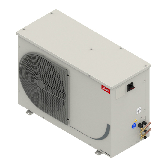
Optyma™ Slim Pack
OP-LPQE/MPVE/MPME
Name plate
A
OP-MPVE034MLW04E
114X7039
B
C
Application
MBP
D
Refrigerant
(1) R404A, R507, R22,
R448A, R449A, R452A
E
M.W.P. HP
(1) 28 bar
LP
(1) 7 bar
F
Voltage
380-400V3N~/50Hz
LRA
30.5 A
OIL INSIDE POE 46
G
Serial No.
123456CG0514
Barcode Serial No:
EAN No.
XXXXXXXXXXX
Danfoss A/S, 6430 Nordborg, Denmark
* For exact values please refer name plate in unit
A: Model
B: Code number
C: Application, Protection
D: Refrigerant
E: Housing Service Pressure
F: Supply voltage, Locked Rotor Ampere,
Maximum Current Consumption
G: Serial Number and bar code
Designation system for the Optyma™ Slim Pack range
OP-MPVE
034 ML W10
1 2 3 4
5
1
Application
M = MBP
L = LBP
2
Package
P = Packaged unit
3
Refrigerant
V= R22/R134a/R513A/R404A/R448A/R449A/R452A
M= R22
Q = R404A/R507/R452A
4
Condenser
E: Extreme and tropical ambient conditions up to 48°C
5
Swept volume
Swept volume in CC
6
Compressor platform
ML = MLZ (Scroll)
MT = MT (Reciprocating)
NT = NTZ (Reciprocating)
LL = LLZ (Scroll)
7
Version
See version control table - W02, W04, W08 and W10
8
Voltage code
G = Compressor 230V/1N~/50Hz, fan 230V/1~/50Hz
E = Compressor 400V/3N~/50Hz, fan 230V/1~/50Hz
© Danfoss | DCS (CC) | 2020.06
MADE IN INDIA
IP54
N
(2) R134a, R513A
(2) 23 bar
(2) 5 bar
MCC
7.5 A
Picture 1 : Minimum mounting distances
L
[mm]
250
E
6
7
8
L
O
M
M
N
O
[mm]
[mm]
[mm]
650
550
550
7. Version control
Service valves
Low Pressure cartridge
Receiver
Filter drier
Sight Glass
Solenoid Valve
Cranckase Heater (Only for LBP models)
Full Ebox
Fan speed controller
Dual Pressure switch KP
HP alarm provision
LP alarm Provision
Discharge gas thermostat provision
Installation and servicing of the conden-
sing units by qualified personnel only.
Follow these instructions and sound refri-
geration engineering practice relating to
installation, commissioning, maintenance
and service.
The condensing unit must only be used for
its designed purpose(s) and within its scope of
application.
Under all circumstances, the EN378 (or
other applicable local safety regulation)
requirements must be fulfilled.
The condensing unit is delivered under nitro-
gen gas pressure (1 bar) and hence it cannot
be connected as it is; refer to the «installation»
section for further details.
The condensing unit must be handled with cau-
tion in the vertical position (maximum offset
from the vertical : 15°)
W02
W04
118A0665C - AN238286441930en-001401 | 1
W08
W10
Advertisement

Subscribe to Our Youtube Channel
Related Manuals for Danfoss Optyma OP-LPQE Series


Summary of Contents for Danfoss Optyma OP-LPQE Series
- Page 1 LL = LLZ (Scroll) Version See version control table - W02, W04, W08 and W10 Voltage code G = Compressor 230V/1N~/50Hz, fan 230V/1~/50Hz E = Compressor 400V/3N~/50Hz, fan 230V/1~/50Hz © Danfoss | DCS (CC) | 2020.06 118A0665C - AN238286441930en-001401 | 1...
- Page 2 • Connect a vacuum pump to both the LP & HP • Ensure a foundation with horizontal surface sides. A DGT accessory is available from Danfoss: refer (less than 3° slope), strong and stable enough • Pull down the system under a vacuum of 500 to section “Spare parts &...
- Page 3 When Fan speed Controller is at factory setting (19 bar): - Maximum number of turns allowed in clockwise direction (+) = 4. - Maximum number of turns allowed in anti-clockwise direction (-) = 6 © Danfoss | DCS (CC) | 2020.06 118A0665C - AN238286441930en-001401 | 3...
- Page 4 -1 bar (Pe)(30in.Hg) LP, aut. reset LP, man. reset Manual reset Manual reset Test Manual test Test Convertible reset KP 17B 060-539366, 060-539466 LP diff. LP-auto. LP-auto. HP-man. HP-auto. 4 | AN238286441930en-001401 - 118A0665C © Danfoss | DCS (CC) | 2020.06...
- Page 5 OP-LPQE048 - 068, OP-MPVE034 - 046 - 057, OP-MPME048 - 060 Chassis: B2 Optyma Slim Pack OP-LPQE067 - 084 - 098, OP-MPVE068 - 080 - 093 - 099 - 108 Chassis: B3 Optyma Slim Pack © Danfoss | DCS (CC) | 2020.06 118A0665C - AN238286441930en-001401 | 5...
- Page 6 Instructions Code G (version W02): OP-MPVE034 - 046 & OP-MPME048 - 060 & OP-MPZE060 Code G (version W02): OP-MPVE068 - 080 - 093 6 | AN238286441930en-001401 - 118A0665C © Danfoss | DCS (CC) | 2020.06...
- Page 7 Code E (version W02) : OP-MPVE034 - 046 - 068 - 080 - 099 - 108 & OP-MPME048 - 060 Code G (version W04): OP-MPVE034 - 046 - 057 & OP-MPME048 - 060 & LPQE048 - 068 © Danfoss | DCS (CC) | 2020.06 118A0665C - AN238286441930en-001401 | 7...
- Page 8 Code E (version W04) : OP-MPVE034 - 046 - 057 - 068 - 080 - 099 - 108; OP-MPME048 - 060; OP-LPQE048 - 067 - 068 - 084 - 098 8 | AN238286441930en-001401 - 118A0665C © Danfoss | DCS (CC) | 2020.06...
- Page 9 Instructions Code E (version W08) : OP-MPVE046 - 068 - 080 - 099 - 108 Code G (version W10) : OP-MPVE034 -046- 057; OP-LPQE048 - 068 © Danfoss | DCS (CC) | 2020.06 118A0665C - AN238286441930en-001401 | 9...
- Page 10 Instructions Code E (version W10) : OP-MPVE046 - 057; OP-LPQE048 - 068 Code G (Version W10) : OP-MPVE068-080 WD10 10 | AN238286441930en-001401 - 118A0665C © Danfoss | DCS (CC) | 2020.06...
- Page 11 Room thermostat Start capacitor compressor Compressor Discharge gas thermostat white Run capacitor compressor Fan motor Terminals E1, E1* Crankcase heater K1, K1* Contactor Solenoid valve Main switch Start relay © Danfoss | DCS (CC) | 2020.06 118A0665C - AN238286441930en-001401 | 11...
- Page 12 Danfoss can accept no responsibility for possible errors in catalogues, brochures and other printed material. Danfoss reserves the right to alter its products without notice. This also applies to products already on order provided that such alterations can be made without subsequential changes being necessary in specifications already agreed. All trade- marks in this material are property of the respective companies.
Need help?
Do you have a question about the Optyma OP-LPQE Series and is the answer not in the manual?
Questions and answers