
Related Manuals for SUTO S605


Summary of Contents for SUTO S605
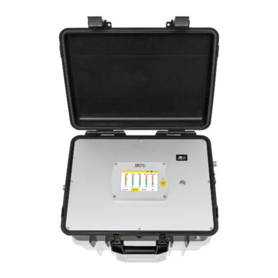
- Page 1 English Instruction and Operation Manual S605 Portable Breathing Air Quality Analyzer...
- Page 2 The device is designed exclusively for the described application. We offer no guarantee for the suitability for any other purpose. We are also not liable for consequential damage resulting from the delivery, capability or use of this device. S605...
-
Page 3: Table Of Contents
9.2 Value View................24 9.3 Graphic View..............24 9.4 Menu.................25 9.5 Configure S4A Remote Connection.........27 9.6 SIM Card Requirement for 4G/LTE Option.......27 9.6.1 Data Traffic..............27 9.6.2 PIN Code Protection............27 10 Guided Measurement...............28 10.1 Steps for Guided Measurement..........30 10.2 Reports for Guided Measurements........32 S605... - Page 4 12.1 Calibration for DP Sensor and Oil Sensor.......35 12.2 Calibration for O2, CO, CO2 Sensor........35 12.2.1 Calibration Gases............36 12.2.2 Calibration Procedure...........36 13 Optional Accessories..............42 14 Maintenance................42 15 Disposal or Waste..............42 16 Warranty................42 17 Appendix - Modbus Holding Register Table........43 17.1 Modbus Interface...............43 17.2 Modbus Register Table............44 S605...
-
Page 5: Safety Instructions
• maintenance work. • Do not exceed the permitted operating parameters as specified in the data sheet, this manual or written on the instrument. • Make sure the product is operated in its permitted limitations. S605... - Page 6 Or you may use any reference meter. Only after doing these examinations, you can rely on the measurement results after the instrument have been used for other measurement cycles. S605...
- Page 7 • purging air in prior to the use of the instrument through the test kit. A clean tissue may help to identify oil, water or any other lubricants in the air. S605...
-
Page 8: Registered Trademarks
EN 12021 or CFSR 1910.134(d). The S605 is mainly used in an industrial environment. It can not be used in hazardous or explosive environment and it not suited for permanent outside applications. -
Page 9: Technical Data
Humidity of the medium < 40%, non condensation Temperature of the medium 0°C ... +45°C Operation pressure 0.4 ... 1.5 MPa(g) Higher pressure needs an external pressure reducer. Storage & Transport temperature -10°C ... + 50°C Ambient temperature 0°C ... +50°C S605... -
Page 10: Measurement Data
Sensor principle Photo ionization detector UV lamp lifetime 6,000 working hours or 1 year, whichever comes first Oil Mist and Particle Sensor (only for S605-C version) Measuring range 0.0 ... 5.0 mg/m³ (Based on 1000 hPa(a), 20°C, 0% relative humidity) Accuracy 15% of reading ±... - Page 11 ±2 °C Td (-70...0 °C Td) ±3 °C Td (-100… -70 °C Td) Resolution 0.1 °C Td Sensor principle QCM + Polymer Pressure Sensor Measuring range 0... 16 bar(g) Accuracy 0.5% FS Resolution 0.01 bar Sensor principle Piezzo resistive pressure sensor S605...
-
Page 12: Dimensional Drawings
6 Dimensional Drawings 6 Dimensional Drawings Dimension of S605 in mm (cover closed): S605... -
Page 13: Installation On Site
7 Installation on Site Please make sure that all components listed below are included in your package. Qty. Description Item No. S605 Portable Breathing Air Quality Analyzer, in a hand carrying case with handle and shoulder belt S605-I version: USB OTG memory stick... -
Page 14: Compressed Air Inlet
7 Installation on Site 7.1 Compressed Air Inlet The compressed air inlet is located on the right side of the S605 housing. S605-I right view ATTENTION! Permissible pressure! Please observe the maximum permissible inlet pressure. If the pressure exceeds the range, the device will be damaged. -
Page 15: Compressed Air Connections
• The tubes should be not bended heavily and should be installed with a big curve radius to avoid turbulence in the air flow. Connect the S605 to the power during the measurement, and • make sure that the device is not turned off or plugged off during the measurement because data will then be lost. -
Page 16: Installation
In case you are not sure, please contact the manufacturer. 7.2.2 Installation 1. Remove the protection cap from the air inlet of the S605. 2. Connect your compressed air system to the air inlet of the S605 by using the supplied Teflon hose. Notes: •... -
Page 17: Electrical Connectors
7.4 Electrical Connections 7.4.1 RS-485 Networking (Modbus/RTU) Through the M12 connector, the S605 can be connected to the RS-485 network over the Modbus/RTU protocol. The RS-485 networking uses the following 3 pins in the M12 connector. The pin functions are described below. -
Page 18: Tcp/Ip Networking (Modbus/Tcp)
Appendix - Modbus Holding Register Table. 7.4.3 Connect with a PC or an OTG USB Stick Through the USB port on the front panel, the S605 can be connected with: • An OTG memory stick: To import firmware for upgrade and to export data. -
Page 19: Calibration Connector
7.6 Calibration Connector The calibration connector is located on the right side of the S605. When the sensors need to be calibrated, remove the connector cap, then connect the calibration hose. When the calibration is finished, put on the cap to avoid the dust or other substance entering. -
Page 20: Setup And Configuration
8 Setup and Configuration 8 Setup and Configuration The S605 is configured ex-works and ready to work when you get it. The S605 provides a guided measurement procedure to take you through device setup for each measurement parameter. All these setup settings are automatically saved into the device even on a power failure. -
Page 21: Operation
9 Operation 9 Operation After the S605 is powered on, the initialization screen is displayed with an active progress bar. During the initialization, the device configures the sensors and runs initialization routines. After the initialization is completed, the system information is shown including device type, serial number, and more. - Page 22 No goes to the Value screen. Note: If your system pressure is greater than 15 bar, be sure to enter your system pressure correctly, otherwise it may affect the measurement! The value screen appears, as shown on the left. S605...
-
Page 23: Main Screen
Low water level indication High water level indication 4G/LTE signal strength S4A remote connected Data logger status: - STOP—Indicates that the data logger is not running. - LOG—Indicates that the data logger is running. S605... -
Page 24: Value View
The graphic view is pre-configured in the factory, and you do not need to change anything. If you make changes, follow the description below. Item Description Y-axes Touch Y-axes to scale it. X-axes Touch X-axes to define viewing period. S605... -
Page 25: Menu
• To view device information, such as the serial number, firmware and hardware versions. To calibrate the touch screen if it does not respond to user inputs • correctly or precisely. • To update the system firmware. S605... - Page 26 Modbus/RTU protocol. You can configure the communication parameters such as address, baud rate etc. • S4A Remote: Used to configure the S605 to connect to the S4A remote server, viewing the measurement values, and reading out the logging files via the S4A software.
-
Page 27: Configure S4A Remote Connection
S4A remote function, customer needs to buy a SIM card locally. 9.6.1 Data Traffic Data traffic required is 7 GB/month if the system is running 7×24 hours. 9.6.2 PIN Code Protection The S605 does not support modifying PIN code on the screen. If your S605... -
Page 28: Guided Measurement
SIM card has PIN code protection, disable it by using other devices, for instance using your mobile phone. 10 Guided Measurement The S605 provides a software-based guided measurement which takes you through the complete measurement. This leads to a simplified measurement process and prevents you from wrong measurements. - Page 29 Guided Measurement. 4. Before starting the measurement, it is recommended to select the standard to be followed first. The S605 will set the alarm threshold according to the selected standard, evaluate the air quality according to the standard, and show all the information in the report.
-
Page 30: Steps For Guided Measurement
The Monitoring with manual stop indicates that no • measurement duration needs to be entered. The Monitoring until values valid indicates the measurement • duration and the valid time duration need to be entered. S605... - Page 31 4. The system checks whether the pressure is in the valid range or not. 5. A pop-up appears and asks if the cleaning is needed. If you click Yes, the cleaning process starts. If you click NO, the measurement starts. S605...
-
Page 32: Reports For Guided Measurements
10.2 Reports for Guided Measurements After performing guided measurements, you can view and manage measurement files through Menu > Files > Reports. To copy or delete files, select the file radio boxes, and click the corresponding button at the bottom. S605... -
Page 33: Firmware Updates
11 Firmware Updates 11 Firmware Updates To update the firmware, just need a OTG-USB drive(supplied with the S605) and the firmware file (format like DIS605_1.82.tar) 1. Insert the USB drive to the connector on the front panel. Make sure to do this after the S605 has fully booted. - Page 34 Make sure you do not disconnect the USB drive. Wait until the device is fully booted again before removing the USB drive. After the update is done, you can select the new language or use new functions offered in the update. S605...
-
Page 35: Calibration
The O sensor, CO sensor, and CO sensor can be calibrated on site or replaced with calibrated sensors using the exchange service of SUTO. ATTENTION! Please save all your measurement data on an external device before returning the instrument to calibration and service. -
Page 36: Calibration Gases
1000 ppm CO Uncertainty of gases is 1% (K=2) Attention! Please select the suitable calibration gas, otherwise the sensor measurement accuracy will be affected. 12.2.2 Calibration Procedure You can enter the calibration through Menu > Calibration. S605... - Page 37 Do not inhale the calibration gas. It can be harmful to health or even death! User Calibration Settings The calibration reference data can be set before the calibration through Menu > Calibration > User Calibration Settings. Zero calibration Enter the zero calibration through Menu > Calibration > Zero S605...
- Page 38 2. Screw off the cap from calibration connector if not. Connect the calibration hose from the gas cylinder to the calibration connector. 4. Adjust the flow controller at the gas cylinder to 0.5 l/min and the output pressure must 0 bar(g). Select Menu > Calibration > Zero/Span calibration. S605...
- Page 39 Just perform the same steps as above, but select the test in the span calibration menu. Calibration Records You can check the calibration records through Menu > Files > Calibration Records. Example for calibration records file: S605...
- Page 40 12 Calibration The figure below is an example for the gas connection. S605...
- Page 41 CO: 20 ppm CO, N background : 1000 ppm CO background 34L, steel calibration gas cylinders Test Gas MESA CO: 10 ppm CO, N background : 500 ppm CO background 34L, steel calibration gas cylinders Transport MESA Carrying cases casing ID:500 Website: https://mesagas.com/ S605...
-
Page 42: Optional Accessories
Please find the warranty as a separated warranty card included with the instrument delivery. The warranty does not cover any wear parts or consumables, therefore the UV lamp with limited lifetime as well as the internal filter are not covered by the warranty. S605... -
Page 43: Appendix - Modbus Holding Register Table
(EMMMMMMM *) SEEEEEEE) Byte 0 Byte 3 UINT32 1-0-3-2 Byte 1 Byte 2 INT32 Byte 1 Byte 0 UINT16 INT16 Byte 1 Byte 0 UINT8 XXX * DATA INT8 * S: Sign, E: Exponent, M: Mantissa, XXX: no value S605... -
Page 44: Modbus Register Table
High Byte is set to 0xFF Date time (8-bytes) 2005 DOUBLE 8-Byte Calibration date format is time- variant (Microsoft) Valid days from calibration 2009 INT16U 2-Byte date Number of Measuring 2010 INT16U 2-Byte 1...96 Channels 2011 STRING 16-Byte Device description “S605” etc. S605... - Page 45 16-Byte Device Location text User can enter a 2035 STRING 16-Byte Measurement Point text How many and which SUTO sensors are connected to 2043 INT16U 2-Byte Number of sensors the main unit. Their settings are found from 10000 Modbus/RTU Settings Response: →...
- Page 46 2-Byte Relay port/status relay close 1= channel alarm relay open bit 14: 0 = summary relay close 1 = summary relay open For S605: Always 0XFFFF: don’t support 2137 FLOAT 4-Byte CO2 High alarm threshold 2139 FLOAT 4-Byte CO2 Low alarm threshold...
- Page 47 Pressure: 2205 INT16U 2-Byte unit+resolution+type Temp.: 2206 INT16U 2-Byte unit+resolution+type Humidity Gas Sensor: 2207 INT16U 2-Byte unit+resolution+type Measurement Channel Status and Values 2300 INT16U 2-Byte Status (channels 1...8) Status information, with 2 bits: 2301 FLOAT 4-Byte Channel Value O2 S605...
- Page 48 4-Byte Channel Value Temperature 10 Sensor broken 11 Other error Channel Value Humidity 2315 FLOAT 4-Byte Gas S. Device specific System Information for S605 Bit1 bit0(water level): 00 : normal low level indicator high level indicator Bit 2: O2 Bit 3: CO2...
- Page 49 10007 FLOAT 4-Byte reference value User calibration point 0 10009 FLOAT 4-Byte actual value User calibration point 1 10011 FLOAT 4-Byte reference value (Reserved) User calibration point 1 10013 FLOAT 4-Byte actual value (Reserved) BYTE[1 10500 CO2 sensor settings S605...
- Page 50 User calibration point 1 11013 FLOAT 4-Byte actual value (Reserved) BYTE[1 H2O sensor settings 11500 (this is the dew point sensor) 11500 INT32U 4-Byte Serial number Factory S/N High = 0xFF, HW version 10 = 11502 INT16U 2-Byte Low byte HW version S605...
- Page 51 Serial number Factory S/N High = 0xFF, HW version 10 = 12502 INT16U 2-Byte Low byte HW version New firmware FW version (low 3 Bytes 12503 INT32U 4-Byte version format: used) XX.XX.XX Atmospheric pressure (in 12505 FLOAT 4-Byte hPa) S605...
- Page 52 SUTO iTEC GmbH SUTO iTEC (ASIA) Co., Ltd. Grißheimer Weg 21 Room 10, 6/F, Block B, Cambridge Plaza D-79423 Heitersheim 188 San Wan Road, Sheung Shui, N.T. Germany Hong Kong Tel: +49 (0) 7634 50488 00 Tel: +852 2328 9782 Email: sales@suto-itec.com...
Need help?
Do you have a question about the S605 and is the answer not in the manual?
Questions and answers