SUTO S421 Instruction And Operation Manual
Thermal mass fow meter (inline)
Hide thumbs
Also See for S421:
- Instruction and operation manual (40 pages) ,
- Instruction and operation manual (40 pages) ,
- Instruction and operation manual (44 pages)
Table of Contents
Advertisement
Quick Links
Advertisement
Table of Contents

Related Manuals for SUTO S421


Summary of Contents for SUTO S421
- Page 1 English Instruction and Operation Manual S421 Thermal Mass Fow Meter (Inline)
- Page 2 The device is designed exclusively for the described application. SUTO offers no guarantee for suitability for any other purpose. SUTO is also not liable for consequential damage resulting from the delivery, capability, or use of this device.
-
Page 3: Table Of Contents
10.2.2 Pulse Connection Diagrams (A1413).......29 10.3 Modbus Interface...............31 10.3.1 Modbus Information.............31 10.3.2 Connect Modbus/RTU Devices to a Master.......32 10.4 M-Bus Output..............36 10.5 Connection between S421 Outputs and Customer Equipment. .37 11 Configuration................41 11.1 Service App S4C-FS............41 11.2 Device Display (Optional)............42 11.2.1 Start-up..............43 11.2.2 Operations..............44... -
Page 4: Safety Instructions
• Consider all regulations for electrical installations. • The system must be disconnected from any power supply during maintenance. • Any electrical work on the system is only allowed by authorized qualified personal. S421... - Page 5 • Always observe the direction of the flow when installing the device. The direction is indicated on the housing. • Do not exceed the maximum operating temperature at the sensor tip. • Avoid condensation on the sensor element as this will affect accuracy enormously. S421...
-
Page 6: Registered Trademarks
• Avoid direct UV and solar radiation during storage. • For the storage, the humidity must be <90% with no condensation. 2 Registered Trademarks Trademark Trademark owner SUTO ® SUTO iTEC MODBUS ® Modbus Organization, Hopkinton, USA HART ® HART Communication Foundation, Austin, USA Android™,... -
Page 7: Rf Exposure Information And Statement
• Consult the dealer or an experienced radio/TV technician for help 。 • This device and its antenna(s) must not be co-located or operating in conjunction with any other antenna or transmitter. S421... -
Page 8: Application
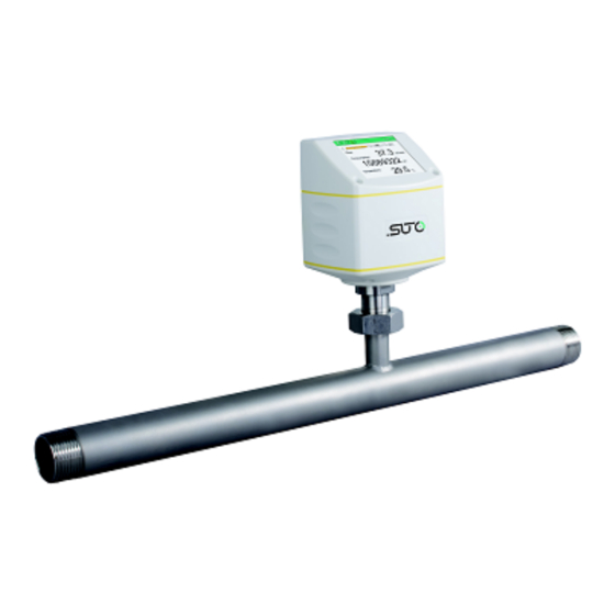
4 Application 4 Application The S421 is the inline-type flow meter that is designed to measure the consumption of compressed air and gases within the permissible operating parameters. (See chapter 6 Technical Data on the next page.) The S421 can measure the following values: •... -
Page 9: Technical Data
6 Technical Data 6 Technical Data 6.1 General FCC ID: 2ASK2-SUTO-001 Parameters Standard unit (flow): Other units (flow): /min, l/min, l/s, cfm, kg/h, kg/min, kg/s Units (Consumption): , ft , kg Reference conditions ISO1217 20°C 1000 hPa (Standard-Unit) DIN1343 0°C 1013.25 hPa (Norm-Unit) -
Page 10: Output-Signals
±0.25% of reading *Specified accuracy is valid only within the minimum and maximum flow rates that are indicated in section on this page. 6.5 Volumetric Vlow Ranges Inch S421 (m³/h) ½" DN15 0.5 ... 90 ¾" DN20 0.9 ... 170 1"... - Page 11 • To calculate flow ranges based on pipe sizes and reference conditions in your site, download and install the free "Flow range calculator" tool from http://www.suto-itec.com. • To fast access the tool download page, enter "flowrange" (without spaces) in the search field.
-
Page 12: Dimensional Drawing
1/2”/(DN15) 197.4 186.7 R 1/2” S421-3/4” 3/4”/(DN20) 200.2 186.7 R 3/4” S421-1” 1”/(DN25) 203.6 186.7 R 1” S421-1 1/4” 1 1/4”/ 207.9 186.7 R 1 1/4” (DN32) S421-1 1/2” 1 1/2”/ 210.9 186.7 R 1 1/2” (DN40) S421-2” 2”/(DN50) 216.9 186.7... - Page 13 (mm) [mm] S421-1/2" 1/2”(DN15) 234.2 186.7 4xØ14 S421-3/4” 3/4”/ 239.2 186.7 4xØ14 (DN20) S421-1” 1”/(DN25) 244.2 186.7 4xØ14 S421-1 1/4” 11/4”/ 256.7 186.7 4xØ18 (DN32) S421-1 1/2” 11/2”/ 261.7 186.7 4xØ18 (DN40) S421-2” 2”/(DN50) 269.2 186.7 4xØ18 S421-2 1/2” 2 1/2”/ 287.1...
- Page 14 4xØ15.7 (DN15) S421-3/4” 3/4”/ 245.4 186.7 117.3 82.5 4xØ19 (DN20) S421-1” 1”/ 248.7 186.7 123.9 88.9 4xØ19 (DN25) S421-1 1/4” 1 1/4”/ 253.4 186.7 133.3 98.5 4xØ19 (DN32) S421-1 1/2” 1 1/2”/ 264.4 186.7 155.4 114.3 4xØ22.3 (DN40) S421-2” 2”/ 269.3...
-
Page 15: Determe The Installation Point
• The flow meter is for indoor use only! At an outdoor installation, the flow meter must be protected from solar radiation and rain. • It is strongly recommended not to install S421 permanently in a wet environment such as the place right after a compressor outlet. - Page 16 8 Determe the Installation Point The S421 comes with a measuring section and a straight inlet section. Nevertheless, additional straight inlet sections must be added to the measuring section to meet the minimum inlet requirements. Please refer to the installation types below and select your additional inlet section 'LA' from the table.
- Page 17 1100 1300 3. 90° Bend Section size DN15 DN20 DN25 DN32 DN40 DN50 DN65 DN80 LA (mm) 1100 1300 4. 2 x 90° Bend Section size DN15 DN20 DN25 DN32 DN40 DN50 DN65 DN80 LA (mm) 1100 1500 1700 S421...
- Page 18 DN20 DN25 DN32 DN40 DN50 DN65 DN80 LA (mm) 1100 1500 1800 2400 3200 3800 8. Filter or similar (unknown objects) Section size DN15 DN20 DN25 DN32 DN40 DN50 DN65 DN80 LA (mm) 1100 1500 1800 2400 3200 3800 S421...
-
Page 19: Installation
A1321 ... A1328 (Flange, EN-1092-1) A1341 ... A1348 (Flange, ANSI 16.5) 9.1 Install the Flow Meter The S421 is shipped with a mounted measurement section. Please make sure that the flow meter is installed correctly to the flow direction in the tube. -
Page 20: Remove The Flow Meter
2. Release the connection nut at the connection thread. 3. Pull out the shaft slowly. 4. The measuring section can be closed with the optional closing cap so that the system can operate normally during maintenance of the flow meter. S421... -
Page 21: Electrical Connection
Re-installation after maintenance: 1. Place the O-ring into the recess of the connection nut. 2. Insert the flow meter back to the pipe. (The S421 comes with the Poka-Yoke design for simple and error-free insertion.) 3. Tighten the connection nut. - Page 22 4 ... 20mA+pulse, active active compatible to S400 (P/N: A1413) Modbus/TCP (P/N: A1424) See section 9.3.2. M-Bus + 4… 20 mA active active + Pulse Pin compatible to M-Bus M-Bus S400 (P/N: A1414) Wire color Brown White Blue Black Grey S421...
- Page 23 Modbus/RTU data - M-Bus M-Bus data Active 4 ... 20 mA signal (related to -V active Active pulse ouput (related to -V active Not applicable ATTENTION! Do not screw the M12 connector using force. Otherwise it might damage the connecting pins. S421...
-
Page 24: Ethernet Connection
When Modbus/TCP is chosen as the flow meter output, a 5 m 8-pore cable is supplied in the delivery package. The cable has the M12 and RJ45 plugs on the ends. RJ45 is used to connect the flow meter to a PoE switch. Front view of the M12 plug, female S421... - Page 25 Orange (O) Rx+ / -V / +V White-Green (W-G) Pair 3 Rx- / -V / +V Green (G) NA / -V White-Brown (W-BR) Pair 4 NA / -V Brown (BR) NA/ +V White-Blue (W-BL) Pair 1 Blue (BL) NA/ +V S421...
-
Page 26: Signal Outputs
0 to max flow. The corresponding flow rates to different pipe sizes can be calculated using the free "Flow range calculator" tool available in http://www.suto-itec.com. For more information about how to download, see section on page 10. - Page 27 10 Signal Outputs If the flow rate is too high, the S421 cannot output the pulses with default settings (one pulse per consumption unit). In this case, you can set the pulse to 1 pulse per 10 consumption units or 1 pulse per 100 consumption units, using the S4C-FS service App (S4C-FS) or a connected display.
-
Page 28: Pulse Connection Diagrams (A1410)
10 Signal Outputs 10.2.1 Pulse Connection Diagrams (A1410) Using the isolated pulse switch (Connector B: Pin 2 and 3) Variant 1: Variant 2: S421... -
Page 29: Pulse Connection Diagrams (A1413)
10 Signal Outputs 10.2.2 Pulse Connection Diagrams (A1413) Using the isolated pulse switch (Connector B: Pin 4 and 5) Variant 1: Variant 2: S421... - Page 30 10 Signal Outputs Using the Pulse Output P+ (Connector A: Pin 5) Variant 1: Variant 2: *GND of the external pulse counter might be connected to -V of the flow meter. S421...
-
Page 31: Modbus Interface
(EMMMMMMM *) SEEEEEEE) Byte 0 Byte 3 UINT32 1-0-3-2 Byte 1 Byte 2 INT32 Byte 1 Byte 0 UINT16 INT16 Byte 1 Byte 0 UINT8 XXX * DATA INT8 * S: Sign, E: Exponent, M: Mantissa, XXX: no value S421... -
Page 32: Connect Modbus/Rtu Devices To A Master
10.3.2 Connect Modbus/RTU Devices to a Master Sensors and devices with a Modbus/RTU output can be connected to a Modbus master device. This master can be either SUTO displays and gateways or any third-party Modbus/RTU master. See below specifications of the Modbus/RTU connections. - Page 33 (A553 0123). • The shield must be connected at one end to the master GND connection. • At the end of the bus, a 120 Ohm resistor should be placed a termination resistor. See the below picture for details. S421...
- Page 34 10 Signal Outputs 10.3.2.3 Daisy-Chain using RS-485 Splitter SUTO devices with M12 connectors can be easily connected in a Modbus/RTU daisy-chain using a M12 RS-485 splitter (A554 3310). Furthermore this allows to easily place the M12 termination resistor (C219 0055) at the last splitter in the bus-chain.
- Page 35 Make sure that at the end of the bus line, the termination resistor of 120 Ohm is placed to avoid interferences. Recommended connection of Modbus/RTU salves in a daisy-chain topology. Avoid a connection of slaves to the master in ring or star topology. S421...
-
Page 36: M-Bus Output
: 8-digit serial number of the device Manufacturer Code : 0x15C4 M-Bus version Baud rate : 2400 Response delay (ms) Response timeout (ms) : 100 Receive timeout (ms) : 500 Value register M-Bus Addr. Description Data bytes Total consumption 4-byte Flow 4-byte M-Bus status 4-byte S421... -
Page 37: Connection Between S421 Outputs And Customer Equipment
10.5 Connection between S421 Outputs and Customer Equipment This section provides figures to show how outputs supported by the S421 connect with the customer equipment. In the following figures, the SUTO Instrument indicates the S421. Analog output (Isolated) Analog output (3-wire) Note: The output applies to option A1413. - Page 38 10 Signal Outputs Modbus/RTU output M-Bus output Modbus/TCP output with PoE Class A S421...
- Page 39 10 Signal Outputs Class B Modbus/TCP output with external power supply Class A S421...
- Page 40 10 Signal Outputs Class B S421...
-
Page 41: Configuration
S4C-FS is an Android-based app that enables you to view measurement readings and change settings for SUTO flow sensors wirelessly. You can download S4C-FS from Google Play Store or SUTO website, and install it as you do for any apps on your Android devices. -
Page 42: Device Display (Optional)
• Change the flow meter settings. Operation keys Enter key Press for >3 seconds to enter the configuration mode. Press to confirm your selection. Up key Press to choose a parameter item, entry box, or to Down adjust the value. S421... -
Page 43: Start-Up
Icons shown in the status bar Indicate status or warnings for the flow meter in service. Icon Description Icon Description Calibration expired Pressure sensor damaged Temperature over Temperature sensor operating range damaged Flow over measuring Flow direction range Pressure over operating range S421... -
Page 44: Operations
3. Use the “Up” and “Down” keys to choose a setting that needs to be changed. 4. Use the “Up” and “Down” keys to select the desired entry box or adjust the values. 5. Press the “Enter” key to confirm the changes. S421... -
Page 45: Menu Map
11 Configuration 11.2.3 Menu Map S421... - Page 46 11 Configuration S421...
-
Page 47: Calibration
The flow meter, the accessories, and its packings must be disposed of according to your local statutory requirements. The waste can also be carried by the manufacturer of the product. For this, please contact the manufacturer. S421... - Page 48 SUTO iTEC GmbH SUTO iTEC (ASIA) Co., Ltd. Grißheimer Weg 21 Room 10, 6/F, Block B, Cambridge Plaza D-79423 Heitersheim 188 San Wan Road, Sheung Shui, N.T. Germany Hong Kong Tel: +49 (0) 7634 50488 00 Tel: +852 2328 9782 Email: sales@suto-itec.com...
Need help?
Do you have a question about the S421 and is the answer not in the manual?
Questions and answers