
Related Manuals for SUTO S601


Summary of Contents for SUTO S601
- Page 1 English Instruction and operation manual S601 Stationary compressed air purity analyzer...
- Page 2 The device is destined exclusively for the described application. SUTO offers no guarantee for the suitability for any other purpose. SUTO is also not liable for consequential damage resulting from the delivery, capability or use of this device.
-
Page 3: Table Of Contents
8.4.2 Alarm setting..............24 8.4.3 Logger setting..............24 8.4.4 Files................25 8.4.5 Service info ..............26 8.4.6 System setting...............26 8.4.7 Communication...............27 8.5 Configuring S601 using S4C-Display........28 8.5.1 RS-485 settings..............28 8.5.2 Ethernet settings............29 9. Software Installation..............31 10. Optional accessories..............31 11. Maintenance................31 12. Disposal or waste..............31 13. -
Page 4: Safety Instructions
• Any contact with energized parts of the product, may lead to a electrical shock which can lead to serious injuries or even death! • Consider all regulations for electrical installations. • The system must be disconnected from any power supply during maintenance work. S601... - Page 5 • Always observe the direction of the flow when installing the sensor. The direction is indicated on the housing. • Do not exceed the maximum operation temperature at the sensors tip. • Avoid condensation on the sensor element as this will affect the accuracy enormously. S601...
- Page 6 • Observe the measuring point always before measurement if it is free of contamination like water drops, oil drops or other rough contamination. • Should water hit the inner electronics, the senors could be seriously damaged. • Check your measurement point with the enclosed test kit. S601...
-
Page 7: Application
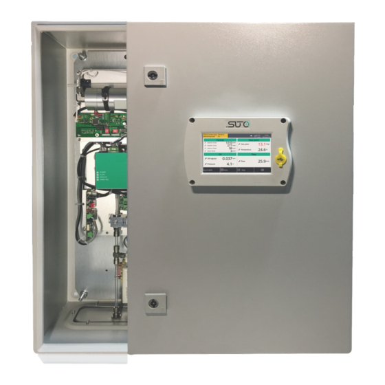
The compressed air purity analyzer S601 is a compact wall-mounted device that measures and records three major quality parameters of compressed air (particle quantity, dew point and temperature). The S601 is mainly used in industrial environments, and not developed to be used in explosive areas. 3. Features •... -
Page 8: Technical Data
Ceramic humidity sensor, oscillating crystal Oil vapor Medium Compressed air, non corrosive components Humidity of the < 40% rH, non condensation medium Temp. of the 0 ... +50°C medium Operation pressure 0.3 ... 1.5 MPa / 43.5 ... 217.6 psig S601... -
Page 9: Electrical Data
50% @ 0.1 < d ≤ 0.15 µm per JIS 100% @ 0.15 µm < d per JIS Dew point ± 2°C Td Oil vapor 5% of value ± 0.003 mg/m Temperature ± 0.2 K Pressure ± 0.08 bar S601... -
Page 10: Dimensions
5. Dimensions 5. Dimensions Dimensions in mm: S601... -
Page 11: Installation On Site
6. Installation on site Please make sure that all components listed below are included in your package. Qty. Description Item No. S601 compressed air analyzer in a wall mountable D500 0601 cabinet USB OTG memory stick A554 0087 Operation and instruction manual... -
Page 12: Mounting The Unit At The Wall
6. Installation on site 6.2 Mounting the unit at the wall S601... -
Page 13: Electrical Connections
• A power supply connector (The cable is inserted through a PG plug and wires are connected to the internal screw terminals.) • An M12 RS-485 connector: To connect S601 to a RS-485 network • A RJ-45 Ethernet connector: To connect S601 to a TCP/IP network In addition, two alarm output relays are provided inside the S601 cabinet. -
Page 14: Rs-485 Networking (Modbus Rtu)
Please observe voltage ranges and power levels! 6.3.2 RS-485 networking (Modbus RTU) Through the M12 connector at the bottom, the S601 can be connected to the RS-485 network over the Modbus RTU protocol. The RS-485 network requires a termination resistor at both far ends of the RS-485 bus. -
Page 15: Tcp/Ip Networking (Modbus Tcp)
Remove the protection cap and plug in the network cable (RJ-45). 6.3.4 Alarm outputs S601 provides two relays for alarm outputs (230 VAC, 3 A) in the S601 cabinet. The following figure shows the back of the S601 display where the two alarm output relays (terminals G and I) are housed. -
Page 16: Compressed Air Connection
6. Installation on site 6.4 Compressed air connection The S601 offers a compressed air input at the bottom of the cabinet, next to the electrical connectors. Installation precautions ATTENTION! Permissible pressure! Please observe the maximum permissible incoming pressure. It must be in between 0.3 and 1.5 MPa. If the pressure exceeds, it will damage the device. - Page 17 3. Check the filter in the test kit for high contamination of water, oil or dust. 4. If the filter is contaminated severely, stop using the S601 to measure because this may lead to serious damage. In case you are not sure, please contact the manufacturer.
-
Page 18: Setup
7. Setup 7. Setup The S601 is configured ex-work and ready to measure out of the box. The setup settings are saved in the device and will not be lost even after a power failure. To ensure an accurate measurement, before measurement, configure the altitude where the device is placed. -
Page 19: Operations And Configurations
8. Operations and configurations 8. Operations and configurations When the S601 is powered on, the initialization screen is displayed with an active progress bar. During the initialization, the device configures the sensors and runs initialization routines. After the initialization is... -
Page 20: Main Screen
8.1.2 Icons in the status bar USB stick connected System error Type of the connected Sensor unit is not sensor does not match matching with with the sensor type configuration configured in the device RTC backup battery Logger status status S601... -
Page 21: Value Screen
Value in the bottom bar. Note: During the first five minutes, the S601 automatically performs a purge process to ensure any remaining particles in the system are blown out. During this period, the counting numbers on the Particle pane appear green and blink. -
Page 22: Graphic Screen
Shows the dynamic graphs of all measurements. To view the graphic screen, press Graphic in the bottom bar. The graphic view is pre-configured in the factory. You can view the S601 measurement graph without configuring anything. In case that you want to manipulate the graph, follow the instructions indicated in the following figure. -
Page 23: Sensor Settings
To ensure an accurate oil vapor measurement, enter the altitude where the S601 is placed. The valid values can be positive only. If the S601 is placed at a negative altitude, please enter 0 instead of the actual negative value. S601... -
Page 24: Alarm Setting
8. Operations and configurations 8.4.2 Alarm setting Enables you to define alarms in the S601. The S601 offers two alarm relay outputs and an optical alarm indication (flashing value). 8.4.3 Logger setting Enables you to start and stop the logger and view logger status. -
Page 25: Files
◦ Wrap around: If the memory is full, new logging data overwrites the oldest data. 8.4.4 Files Shows all recorded log files and screenshots as well as memory status. You can select a log file to view log details or to delete the file. S601... -
Page 26: Service Info
Enables you to view the contacts of the service provider, which can be input using the S4C-Display software. For more information about how to use S4C-Display, see section 8.5 Configuring S601 using S4C-Display 8.4.6 System setting Enables you to configure the S601 general settings. S601... -
Page 27: Communication
Reset To reboot the display. 8.4.7 Communication The menu enables to configure the communication settings for S601. Click the desired button and follow the instruction shown on the display. Modbus master S601 works as the Modbus master. Enter the Modbus communication parameters for S601 to communicate with Modbus slaves. -
Page 28: Configuring S601 Using S4C-Display
Enter the IP address or domain name of the S4M server. 8.5 Configuring S601 using S4C-Display To change the S601 settings, in addition to the S601 display, you can use the configuration software S4C-Display. You can download S4C- Display for free from the SUTO web page at www.suto-itec.com. -
Page 29: Ethernet Settings
• Choose SUTO Protocol if the peer device is using SUTO software. Protocol selection • Choose Modbus if the S601 is connected to a Modbus network. Each device on the RS-485 network needs to have a Address unique device address. Please ensure that address 0 is not used and that there are no duplicated addresses. - Page 30 Modbus if device is connected to a Modbus selection network. After you select this option, the network router will dynamically assign the S601 an IP address. This is Get IP config convenient but not recommended in industrial networks. automatically We recommend you assign a static IP address to the S601.
-
Page 31: Software Installation
9. Software Installation 9. Software Installation Following software is available for download from www.suto-itec.com: S4C-Display Free configuration software Free logger readout and data analysis software Multiple-device data acquisition and analysis software After download, please follow the onscreen instructions to install the software. -
Page 32: Calibration
After you exchange a new sensor unit, remember to input its serial number to the S601 through Menu > System Setting > Device info. 14. Warranty SUTO provides a warranty for this product of 24 months covering the material and workmanship under the stated operating conditions from the date of delivery. - Page 33 • If the warranty sealing is removed or damaged. Other claims, especially those for damage occurring outside the instrument are not included unless responsibility is legally binding. Warranty repairs do not extend the period of warranty. ATTENTION! Batteries have a reduced warranty time of 12 months. S601...
- Page 34 S601...
- Page 35 S601...
- Page 36 SUTO iTEC GmbH SUTO iTEC (Asia) Co., Ltd. Werkstr. 2 Room 10, 6/F, Block B, Cambridge Plaza 79426 Buggingen 188 San Wan Road, Sheung Shui, N.T. Germany Hong Kong Tel: +49 (0) 7631 936889-0 Tel: +852 2328 9782 Fax: +49 (0) 7631 936889-19...
Need help?
Do you have a question about the S601 and is the answer not in the manual?
Questions and answers