
Related Manuals for SUTO S418-V


Summary of Contents for SUTO S418-V
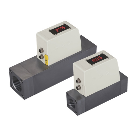
- Page 1 English Instruction and Operation Manual S418-V Compact Thermal Mass Flow Meter for Vacuum Application (Pro-Inline)
- Page 2 The device is designed exclusively for the described application. SUTO offers no guarantee for the suitability for any other purpose. SUTO is also not liable for consequential damage resulting from the delivery, capability or use of this device.
-
Page 3: Table Of Contents
9.1 Analog output..............16 9.2 Pulse output...............16 9.3 Modbus Interface..............18 9.3.1 Modbus Information............18 9.3.2 Connect Several S418-V to Modbus Master.......19 9.3.2.1 Modbus/RTU Cable Length.........19 9.3.2.2 Modbus/RTU Wiring and Cable Type......19 9.3.2.3 Create Daisy-Chain using RS-485 Splitter....20 9.3.2.4 Topology of Modbus/RTU Daisy-Chain......21 10 Configuration................23... -
Page 4: Safety Instructions
• Consider all regulations for electrical installations. • The system must be disconnected from any power supply during maintenance. • Any electrical work on system is only allowed by authorized qualified personal. S418-V... - Page 5 • Always observe the direction of the flow when installing the sensor. The direction is indicated on the housing. • Do not exceed the maximum operation temperature at the sensors tip. • Avoid condensation on the sensor element as this will affect accuracy enormously. S418-V...
-
Page 6: Registered Trademarks
• Avoid direct UV and solar radiation during storage. • For the storage the humidity must be <90%, no condensation. 2 Registered trademarks Trademark Trademark owner SUTO ® SUTO iTEC MODBUS ® Modbus Organization, Hopkinton, USA Android™, Google LLC Google Play... -
Page 7: Rf Exposure Information And Statement
• Consult the dealer or an experienced radio/TV technician for help • This device and its antenna(s) must not be co-located or operating in conjunction with any other antenna or transmitter. S418-V... -
Page 8: Application
4 Application 4 Application The S418-V is a Compact Thermal Mass Flow Meter that is designed to measure the actual flow at the low pressure side of vacuum pumps within the permissible operating parameters (in chapter 6 Technical data). The S418-V can measure the following values: Absolute volumetric flow (default unit: al/min) •... -
Page 9: Technical Data
6 Technical data 6 Technical data 6.1 General data FCC ID: 2ASK2-SUTO-003 Parameters Flow: Actual volumetric flow: l/min, m /min, cfm Consumption: m , ft Medium pressure: bar, psi Principle of measurement Thermal mass flow Sensor Glass coated resistive sensor... -
Page 10: Data Logger
Through mobile app S4C-FS (Free for download on Google Play Store and SUTO Website) Logger readout Through the software S4A via USB (Downloadable on the SUTO website) 6.4 Output signals Analogue output Signal: 4 ... 20 mA, isolated Scaling: 0 to max flow... -
Page 11: Accuracy Of Pressure
Remark: The total consumption value is saved to the permanent memory every 5 minutes. If within these 5 minutes the device is powered off, it will restore the last consumption value which was saved in the last cycle. 7 Dimensional drawing Unit : DN8/DN15 S418-V... - Page 12 7 Dimensional drawing DN20/DN25 S418-V...
-
Page 13: Installation
8 Installation 8 Installation S418-V is delivered with following components: Qty. Description Order no. S418-V Compact Thermal Mass Flow Meter, DN8 / S695 4190 S695 4191 S418-V Compact Thermal Mass Flow Meter, DN15 / S695 4192 S418-V Compact Thermal Mass Flow Meter, DN20 /... -
Page 14: Led Indicators
The flow sensor is equipped with two connectors “A” and “B”. By default the sensor is delivered with one 5 m cable with a M8 connector on one side and open wires on the other side. To make the S418-V work, one S418-V... - Page 15 Pin 3 Pin 4 Modbus Pulse and isolated isolated analog isolated isolated M-Bus M-Bus M-Bus M-Bus M-Bus Wire color Brown White Blue Black ATTENTION! Do not screw the M8 plug using force. Otherwise, it may damage the connecting pins. S418-V...
-
Page 16: Sensor Signal Outputs
The sensor outputs one pulse per consumption unit. This pulse output can be connected to an external pulse counter to count the total consumption. The number of m per second are summed up and indicated after one second. Pulse length depends on flow rate. S418-V... - Page 17 9 Sensor signal outputs Volumetric Volumetric Pulse length Max. pulse flow flow [ms] output per hour ≦ ≦ 10800 1080 > 3 > 10800 2880 > 6 > 21600 3960 Pulse connection diagram Variant 1: Variant 2: S418-V...
-
Page 18: Modbus Interface
Note: Modbus communication settings as well as other settings can be changed by the service App S4C-FS or through the windows based Service Software. Available measurement channels Register Channel name Resolution Format Length address Flow FLOAT 4-byte Consumption UNIT32 4-byte Pressure 0.01 FLOAT 4-byte S418-V... -
Page 19: Connect Several S418-V To Modbus Master
9 Sensor signal outputs 9.3.2 Connect Several S418-V to Modbus Master The S418-V with Modbus/RTU interface can be easily daisy-chained to a Modbus Master device. This master can be either SUTO displays and gateways or any third-party Modbus/RTU master. Through this method you can add up to 16 flow meters to the master device. -
Page 20: Create Daisy-Chain Using Rs-485 Splitter
See the below picture for details. 9.3.2.3 Create Daisy-Chain using RS-485 Splitter To connect the S418-V to the daisy-chain, the RS-485 splitter (A554 3310) and the M8 to M12 converter cable (A553 0161) are needed. Furthermore place a M12 termination resistor (C219 0055) at the last splitter in the daisy-chain, as show in the figure below. -
Page 21: Topology Of Modbus/Rtu Daisy-Chain
Other connection topologies are not recommended and should be avoided. Make sure that at the end of the bus line, the termination resistor of 120 Ohm is placed to avoid interferences. Recommended connection of Modbus/RTU salves in a daisy-chain Topology. S418-V... - Page 22 9 Sensor signal outputs Avoid a connection of Slaves to the master in ring or star topology. Avoid a star topology Avoid a ring topology S418-V...
-
Page 23: Configuration
10 Configuration 10 Configuration To change any settings on the S418-V, download and install the service App S4C-FS from the Google Play store or SUTO Website. This App works on any Android or iOS system with Bluetooth supported. To be allowed to change settings, the App needs to scan the QR code on the calibration certificate. -
Page 24: Read And Analysis Of Measurement Data
• The S418-V log file supports up to 5.6 million records due to its memory size, which is equivalent to 64-day data at the one- second sampling rate. -
Page 25: Operations
11.2 Operations 11.2.1 Logger configuration You can control and configure the S418-V data logger using the S4C-FS App. Detailed steps are as follows. 1. Install and launch the S4C-FS App. For more information, see the S4C-FS Instruction and Operation Manual. - Page 26 6. Click the File menu to have graphic views on measurement data in a log file; and if needed, to export this log file to the Excel or CSV format. For more information about operations on S4A, click the Help button on the top right corner. S418-V...
-
Page 27: Calibration
The sensor, the accessories and its packings must be disposed according to your local statutory requirements. The dispose can also be carried by the manufacturer of the product, for this please contact the manufacturer. S418-V... -
Page 28: Appendix - Specifications
The following table is used to find the appropriate flow meter size depending on the vacuum flow and absolute pressure. Example: If the actual situation is like this: absolution pressure = 300 hPa and vacuum flow = 750 l/min, the S418-V with DN20 will be the proper one. Process Absolute DN15... -
Page 29: Error Codes
Er. 50 Logger failure 14.3 Order table Order no. Code Description S695 419 S418-V S418-V Compact Thermal Mass Flow Meter, 1.5% o.RDG., 24 VDC Connection thread S695 419 DN8 G inner thread DN15 G inner thread DN20 G inner thread... - Page 30 Reverse display direction Accessories Order no. Description A554 3315 T-BOX for S418-V Modbus/M-Bus systems, including 2 m cable with a M8 connector A554 0109 Main power supply 100-240 VAC / 24 VDC, 0.5 A, 2 m cable with M8 connector...
- Page 31 S418-V...
- Page 32 SUTO iTEC GmbH SUTO iTEC (ASIA) Co., Ltd. Grißheimer Weg 21 Room 10, 6/F, Block B, Cambridge Plaza D-79423 Heitersheim 188 San Wan Road, Sheung Shui, N.T. Germany Hong Kong Tel: +49 (0) 7634 50488 00 Tel: +852 2328 9782 Email: sales@suto-itec.com...
Need help?
Do you have a question about the S418-V and is the answer not in the manual?
Questions and answers