SUTO S600 Instruction And Operation Manual
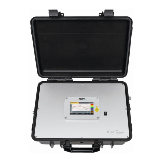
Portable compressed air purity analyzer
Hide thumbs
Also See for S600:
- Instruction and operation manual (48 pages) ,
- Instruction and operation manual (36 pages) ,
- Instruction and operation manual (36 pages)

Subscribe to Our Youtube Channel
Related Manuals for SUTO S600


Summary of Contents for SUTO S600
- Page 1 English Instruction and operation manual S600 Portable compressed air purity analyzer...
- Page 2 The device is designed exclusively for the described application. SUTO offers no guarantee for the suitability for any other purpose. SUTO is also not liable for consequential damage resulting from the delivery, capability or use of this device.
-
Page 3: Table Of Contents
8.3 Main menu................24 8.3.1 Files................25 8.3.2 System Setting...............25 8.4 Icons in the status bar............26 9. Guided measurement..............27 9.1 Steps for guided measurement..........28 9.2 Reports for guided measurements...........32 10. Optional accessories..............33 11. Maintenance................33 12. Calibration................33 13. Disposal or waste..............33 14. Warranty................33 S600... -
Page 4: Safety Instructions
• Any contact with energized parts of the product, may lead to a electrical shock which can lead to serious injuries or even death! • Consider all regulations for electrical installations. • The system must be disconnected from any power supply during maintenance work. S600... - Page 5 • Do not exceed the maximum operation temperature or pressure. • Avoid condensation inside the instrument caused by the supplied air or gas because it harms the instrument and affects the S600...
- Page 6 Please make sure, that your measuring point is free of excessive contamination/dirt. This should maintained before every measurement. • Observe the measuring point always before measurement if it is free of contamination like water drops, oil drops or other rough contaminations. S600...
- Page 7 A clean tissue may help to identify oil, water or any other lubricants in the air. ATTENTION! Overpressure! Remove always all protection caps before connecting the compressed air to the inlet. S600...
-
Page 8: Application
The S600 is mainly used in industrial environments, and is not developed to be used in explosive areas. 3. Features •... -
Page 9: Technical Data
Laser optical detection quantity Dew point Ceramic humidity sensor, oscillating crystal Oil vapor Volume flow Thermal mass flow (Anemometer) Medium Compressed air, non corrosive components Humidity of the < 40%, non condensation medium Temp. of the 0 ... +50°C medium S600... -
Page 10: Electrical Data
100% @ 0.15 μm < d Dew point ± 2°C Td Oil vapor 5% of value ± 0.003 mg/m Volume flow ± (2% of value + 0.3% of range) (isokinetic sampling device only) Temperature ±0.1 K Pressure ±0.08 bar / ±1.1603 psi S600... -
Page 11: Dimensions
5. Dimensions 5. Dimensions Dimensions of S600 in mm (cover closed): S600... - Page 12 5. Dimensions Dimensions of isokinetic sampling device (optional) in mm: S600...
- Page 13 5. Dimensions 3D view of the S600 and the isokinetic sampling device: S600...
-
Page 14: Installation On Site
The tubes should be not bended heavily and should be installed with a big curve radius to avoid turbulence in the air flow. The isokinetic sampling device must be set up next to the S600 to get a straight and short connection. Please observe the following chapter, connecting the isokinetic sampling device to the S600. - Page 15 2. Check the filter in the test kit to see if it shows high contamination of water, oil or dust. 3. If the filter is contaminated severely, stop using the S600 for measurement because this may lead to serious damage to the device.
- Page 16 ATTENTION! Always use the 6 mm Teflon hose adapter to connect the teflon hoses to the S600 and to the isokinetic sampling device! You may damage the device if not used. Directly plugging and pulling the teflon hose more than once may lead to particle contamination, which can affect the measurement.
-
Page 17: Connection With The Optional Isokinetic Sampling Device
On the next page you can find the detailed description of the sampling device. Also you can find which outlets of the sampling device need to be connected to which input at the S600. The following diagrams help you better understand the setup connection. -
Page 18: Connection Without The Isokinetic Sampling Device
5. Connect the isokinetic outlet 4 with the inlet for the particle counting at the S600 using the supplied 6 mm tube and the hose adapters. 6. Now open outlet valve 2 and 4 to pressurize the instrument. -
Page 19: Electrical Connections
6.4 Electrical connections The S600 offers three types of electrical connections. The power supply connector 1, the communication port for the isokinetic sampling device 2 and an Ethernet port 3 to communicate with network devices. -
Page 20: Compressed Air Connections (Inlet And Outlet)
6. Installation on site 6.5 Compressed air connections (inlet and outlet) The S600 offers two compressed air inputs on the right side of the housing. The inlets are shown on the picture above and are marked respectively to their functions: Gas inlet Oil / Dew point measurement and Gas inlet Particle counter measurement. -
Page 21: Setup And Configuration
7. Setup and configuration The S600 is configured ex-works and ready to work out of the box. The S600 provides a guided measurement procedure to take you through device setup for each measurement parameter. All these setup settings are automatically saved into the device even on a power failure. -
Page 22: Operation
8. Operation 8. Operation After the S600 is powered on, the initialization screen is displayed with an active progress bar. During the initialization, the device configures the sensors and runs initialization routines. After the initialization is completed, the date of the last calibration date is shown. -
Page 23: Value View
To switch to the value view, click Value in the bottom. Note: During the first five minutes, the S600 performs a purge process to ensure any remaining particles in the system are blown out. During this period, the counting numbers on the Particle pane appear green and blinking. -
Page 24: Main Menu
To perform general settings on date, time and settings language and so on. To view information such as the serial number. Communication To perform field bus settings and configure communication parameters. Sensor settings To change units for the measured parameters. S600... -
Page 25: Files
To calibrate the touch screen if it does not screen respond to user inputs correctly or precisely. Language To select the interface language. Date time To configure date and time. Device info To view device information such as serial number. S600... -
Page 26: Icons In The Status Bar
Calibration is overdue, please. Contact the The S600 is connected to manufacturer of your a PC by the USB cable. local dealer. Data logger status: - STOP—Indicates that the data logger is not running. -
Page 27: Guided Measurement
9. Guided measurement 9. Guided measurement The S600 provides a software-based guided measurement which takes you through the complete measurement. This leads to a simplified measurement process and prevents you from wrong measurements. To start a guided measurement, do the following: 1. -
Page 28: Steps For Guided Measurement
Click Yes to start. 2. The system asks if you are using the isokinetic sampling device, and this will affect the further steps and instructions. Select Yes if you have the isokinetic sampling device connected. Otherwise, click No. S600... - Page 29 6. Enter how long the measurement will take. The longer it takes, the more stabilized the values will be and the more exactly it will represent the system conditions. S600...
- Page 30 The following 3 steps only apply if you select Yes for the isokinetic sampling device, otherwise skip the next 3 steps 1. The S600 is now ready for measurement. Please read the instructions shown on the screen carefully, and then click Start.
- Page 31 9. Guided measurement 2. Follow the onscreen instructions to proceed. 3. Perform Isokinetic Setup as instructed on the screen. Now the device is well set up and starts to measure data. The remaining time is shown on the top left corner. S600...
-
Page 32: Reports For Guided Measurements
(not the check box on the right). A window appears showing the PDF for your preview. To copy, export , or • delete files, select the file check boxes, and then click the corresponding button at the bottom. S600... -
Page 33: Optional Accessories
12. Calibration The S600 unit is calibrated ex work. The exact calibration date is printed on the certificate which is supplied together with the unit. The accuracy of the unit is regulated by the onsite conditions, and parameters like high oil, high humidity or other impurities can affect the calibration and furthermore the accuracy. - Page 34 14. Warranty the date of delivery. Please report any findings immediately and within the warranty time. If faults occur during the warranty time SUTO will repair or replace the defective unit, without charge for labour and material costs but there is a charge for other service such as transport and packing costs.
- Page 35 S600...
- Page 36 SUTO iTEC GmbH SUTO iTEC (ASIA) Co., Ltd. Werkstr. 2 Room 10, 6/F, Block B, Cambridge Plaza 79426 Buggingen 188 San Wan Road, Sheung Shui, N.T. Germany Hong Kong Tel: +49 (0) 7631 936889-0 Tel: +852 2328 9782 Fax: +49 (0) 7631 936889-19...
Need help?
Do you have a question about the S600 and is the answer not in the manual?
Questions and answers