SUTO S430 Instruction And Operation Manual
Pitot tube flow meter for wet air (insertion)
Hide thumbs
Also See for S430:
- Instruction and operation manual (52 pages) ,
- Instruction and operation manual (32 pages) ,
- Instruction and operation manual (48 pages)

Related Manuals for SUTO S430


Summary of Contents for SUTO S430
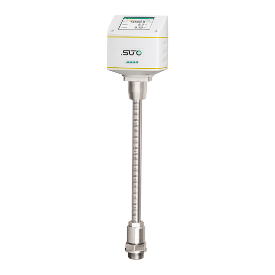
- Page 1 English Instruction and Operation Manual S430 Pitot Tube Flow Meter for Wet Air (Insertion)
- Page 2 The device is designed exclusively for the described application. SUTO offers no guarantee for suitability for any other purpose. SUTO is also not liable for consequential damage that results from the delivery, capability, or use of this device.
-
Page 3: Table Of Contents
9.2 Use Optional Display............31 9.2.1 Start-up..............31 9.2.2 Operations Keys............31 9.2.3 Menu Map..............34 10 Signal Outputs................36 10.1 Analog Output..............36 10.2 Pulse Output..............36 10.2.1 Pulse Connection Diagram..........38 10.3 Modbus Output ..............39 10.3.1 Modbus Parameters...........39 10.3.2 Connect Modbus/RTU Devices to a Master.....41 S430... - Page 4 10.4 M-Bus Output..............45 10.5 Connection between S430 Outputs and Customer Equipment. .45 11 Calibration................49 12 Maintenance................49 13 Disposal or Waste..............49 14 Appendix – Flow Measurement Ranges........50 14.1 Volumetric Flow Ranges............50 14.2 Analog Output..............51 S430...
-
Page 5: Safety Instructions
• Consider all regulations for electrical installations. • The system must be disconnected from any power supply during maintenance work. • Any electrical work on the system is only allowed by authorized qualified personal. S430... - Page 6 • Always observe the direction of the flow when installing the flow meter. The flow direction is indicated on the housing. • Do not exceed the maximum operating temperature at the sensor tip. • Avoid condensation on the flow meter element because it will affect the accuracy enormously. S430...
-
Page 7: Registered Trademarks
• Avoid direct UV and solar radiation during storage. • For the storage, the humidity must be <90% with no condensation. 2 Registered Trademarks Trademark Trademark owner SUTO ® SUTO iTEC MODBUS ® Modbus Organization, Hopkinton, USA Android™, Google LLC Google Play S430... -
Page 8: Rf Exposure Information And Statement
• Connect the equipment into an outlet on a circuit different from that to which the receiver is connected. • Consult the dealer or an experienced radio/TV technician for help • This device and its antenna(s) must not be co-located or operating in conjunction with any other antenna or transmitter. S430... -
Page 9: Application
4 Application 4 Application The S430 Pitot Flow Meter is designed to measure the consumption of compressed air and a variety of industrial gases in wet or high mass flow/velocity applications. The flow meter can even work in wet and dirty gases such as the outlet of a compressor. -
Page 10: Features
Modbus/RTU, Modbus/TCP, or M-Bus. • Optional Power over Ethernet (PoE) for the Modbus/TCP output. • Mobile service App S4C-FS for monitoring and configuring flow sensors on mobile devices. • Optional display for monitoring and configuring values directly on the flow meter. S430... -
Page 11: Technical Data
6 Technical Data 6 Technical Data 6.1 General Data FCC ID: 2ASK2-SUTO-004 Parameters Selectable flow: Volumetric Flow, Actual Flow, Dry Air Flow, Free Air Delivery (FAD), Mass Flow Consumption Velocity (working condition) Medium temperature Medium pressure Selectable units Volumetric Flow:... -
Page 12: Electrical Data
Isolated switch: max. 30 VDC / 200 mA Pulse length: 30 … 120 ms depending on the flow rate Modbus output See section 10.3 on page 39. (default setting) M-Bus output See section 10.4 on page 45. (default setting) S430... -
Page 13: Accuracy
Temperature: 0.5°C Stated accuracy at Ambient/process temperature 23°C ± 3°C Ambient/process humidity <90% Process pressure at 0.6 MPa(g) * The specified accuracy is valid only within the minimum and maximum flows that are indicated in section 14.1 on page 50. S430... - Page 14 30 sm/s cut-off. The cut-off ex factory is to 20 sm/s. Remark: The total consumption value is saved to the permanent memory every 5 minutes. If within these 5 minutes the device is powered off, it will restore the last consumption value which was saved in the last cycle. S430...
-
Page 15: Dimensional Drawing
7 Dimensional Drawing 7 Dimensional Drawing S430... -
Page 16: Installation
8 Installation Before you install the flow meter, make sure that all components listed below are included in your package. Qty Description Item No. S430 Pitot Flow Meter S695 4300 or S695 4302 Sealing ring Alignment key Depending on orders:... -
Page 17: Installation Considerations
• The flow meter is for indoor use only! At an outdoor installation, the flow meter must be protected from solar radiation and rain. Remark: If there is any combination of the following situations, the longest straight inlet section must be maintained. S430... - Page 18 8 Installation Expansion Reduction 90° Bend 2×90° Bend Three dimensional Bend T-piece Shut-off valve Filter or similar (unknown objects) S430...
-
Page 19: Insertion Angles
Please install the flow meter only in the recommended area. Insertion into a vertical pipe As shown in the left figure, the S430 can be installed in a vertical pipe when the following two conditions are met: • The flow direction is from bottom to top. -
Page 20: Calculating The Insertion Depth
= Height of the ball valve Calculation example: A 2”-diameter 、pipe and an 87 mm- height ball valve: OD=60.3 mm 60.3 mm =30.15 mm Height of Valve=87 mm ; Insertion depth = 30.15 mm +87 mm=117.15 mm S430... -
Page 21: 100 Mm-Depth Installation
= Height of the ball valve Calculation example: A 12”-diameter pipe with the wall thickness of 9 mm and a 87 mm-height ball valve. x=9 mm ; y=87 mm Insertion depth = 9 mm+ 87 mm+ 100 mm=196 mm S430... -
Page 22: Install The Flow Meter
8 Installation 8.4 Install the Flow Meter This section describes how to install S430. First please observe the flow direction sign indicated on the flow meter head or on the shaft. It must match the flow direction of the compressed air or gas. - Page 23 10. Tighten the clamp sleeve using a spanner with clamping torque of 20...30 Nm. 11. Double check the installation depth because the shaft might be moved from its original position by the compressed gas. Maximum angle deviation of a proper installation: Figure 1: Top view S430...
-
Page 24: Perform The Zero Flow Calibration
This is the most convenient way especially for a flow meter without the display. 1. On your Android device, download the S4C-FS app from Google Play Store or from the SUTO website. 2. Install S4C-FS. 3. Launch S4C-FS, and enter Settings > Calibration. -
Page 25: Use The Display
8 Installation 8.5.3 Use the Display See steps 4 and 5 described in Figure 3. Figure 3: Steps to perform the zero flow Figure 2: Steps to expose the flow meter calibration to the system pressure S430... -
Page 26: Remove The Flow Meter
5. Unscrew the connection head and pull the flow meter out of the ball valve. 8.7 Performe Electrical Connection The flow meter comes with external connectors "A" and "B" through which the flow meter is connected with external control devices such as PLC. Connector A Connector B S430... -
Page 27: M12 Connectors
Pin 5 Modbus/RTU Pulse and analog isolated isolated M-Bus M-Bus M-Bus Modbus/TCP See section 8.7.2 on next page. Wire color Brown White Blue Black Gray Legend for pin assignment Ground for Modbus/RTU Digital signal (internal use) Negative supply voltage S430... -
Page 28: Ethernet Connection
When Modbus/TCP is chosen as the flow meter output, a 5 m 8-pore cable is supplied in the delivery package, which has the M12 and RJ45 plugs on both ends. RJ45 is used to connect the device to a PoE switch. S430... - Page 29 Orange (O) Rx+ / -V / +V White-Green (W-G) Pair 3 Rx- / -V / +V Green (G) NA / -V White-Brown (W-BR) Pair 4 NA / -V Brown (BR) NA/ +V White-Blue (W-BL) Pair 1 NA/ +V Blue (BL) S430...
-
Page 30: Configuration
9.1 Use Service App S4C-FS S4C-FS is an Android-based app that enables you to view measurement readings and change settings for SUTO flow sensors wirelessly. For more information about description of the flow meter settings, see the S4C-FS Instruction and Operation Manual, which you can download from our website (Download >... -
Page 31: Use Optional Display
9.2.2 Operations Keys Operation keys Enter key Press for >3 seconds to enter the configuration mode. Press to confirm your selection. Up key Press to choose a parameter item, entry box, or to adjust the value. Down key S430... - Page 32 Icons shown in the status bar indicates the status or warnings for the flow meter in service. The following table provides descriptions for these icons. Calibration expired Temperature over operating range Flows over measuring range Pressure over operating range Pressure sensor damaged Temperature sensor damaged Flow direction S430...
- Page 33 3. Use the Up and Down keys to choose the parameter that you want to change. 4. Use the Up Down keys to select desired entry box or adjust the values. 5. Press the Enter key to confirm the changes. S430...
-
Page 34: Menu Map
9 Configuration 9.2.3 Menu Map S430... - Page 35 9 Configuration S430...
-
Page 36: Signal Outputs
The flow meter sends out one pulse per a consumption unit by default. This pulse output can be connected to an external pulse counter to count the total consumption. The number of m per second are accumulated and indicated after one second. Pulse length depends on consumption rate. S430... - Page 37 10 Signal Outputs If the flow rate is higher than 50 m /s, l/s of ft /s, the S430 cannot output the pulses with default settings (one pulse per a consumption unit). In this case, you can set the pulse to 1 pulse per 10 consumption units or 1 pulse per 100 consumption units using by the S4C-FS service app or a connected display.
-
Page 38: Pulse Connection Diagram
10 Signal Outputs 10.2.1 Pulse Connection Diagram Using the isolated pulse switch (Connector B Pin 2 and 3) Variant 1: Variant 2: S430... -
Page 39: Modbus Output
(EMMMMMMM *) SEEEEEEE) Byte 0 Byte 3 UINT32 1-0-3-2 Byte 1 Byte 2 INT32 Byte 1 Byte 0 UINT16 INT16 Byte 1 Byte 0 UINT8 XXX * DATA INT8 * S: Sign, E: Exponent, M: Mantissa, XXX: no value S430... - Page 40 Bit Description Description Measurement over range Pressure sensor broken Temperature over range Temperature sensor broken Pressure over range NTC broken Pulse over range Flow direction: 0: standard; 1: reverse Calibration overdue BT module connected Differential pressure sensor broken S430...
-
Page 41: Connect Modbus/Rtu Devices To A Master
10.3.2 Connect Modbus/RTU Devices to a Master Sensors and devices with a Modbus/RTU output can be connected to a Modbus master device. This master can be either SUTO displays and gateways or any third-party Modbus/RTU master. See below specifications of the Modbus/RTU connections. - Page 42 (A553 0123). • The shield must be connected at one end to the master GND connection. • At the end of the bus, a 120 Ohm resistor should be placed a termination resistor. See the below picture for details. S430...
- Page 43 10 Signal Outputs 10.3.2.3 Daisy-Chain using RS-485 Splitter SUTO devices with M12 connectors can be easily connected in a Modbus/RTU daisy-chain using a M12 RS-485 splitter (A554 3310). Furthermore this allows to easily place the M12 termination resistor (C219 0055) at the last splitter in the bus-chain.
- Page 44 10 Signal Outputs Avoid a connection of slaves to the master in ring or star topology. Avoid a star topology Avoid a ring topology S430...
-
Page 45: M-Bus Output
M-Bus status 4-byte 10.5 Connection between S430 Outputs and Customer Equipment This section provides figures to show how outputs supported by the S430 connect with the customer equipment. In the following figures, the SUTO Instrument indicates the S430. Modbus/RTU output S430... - Page 46 10 Signal Outputs Isoalated 4 ... 20 mA analog output Passive pulse output M-Bus S430...
- Page 47 10 Signal Outputs Modbus/TCP output with PoE Class A Class B S430...
- Page 48 10 Signal Outputs Modbus/TCP output with external power supply Class A Class B S430...
-
Page 49: Calibration
The device, the accessories and its packings must be disposed according to your local statutory requirements. The dispose can also be carried by the manufacturer of the product. Please contact the manufacturer for details. S430... -
Page 50: Appendix - Flow Measurement Ranges
2,612 25,967 Flow range for Air at 6 bar(g), 50°C, and 90% humidity. For other gases and conditions please download Flow Range software from www.suto-itec.com. Remarks: To fast access the tool download page, enter "flowrange" (without spaces) in the search field, and then click the search result. -
Page 51: Analog Output
637.62 10.63 12” 300.00 42750.79 712.51 712513.2 11875.22 25162.2 50778.1 846.30 14.11 309.70 45560.04 759.33 759334.0 12655.57 26815.6 54114.8 901.91 15.03 339.60 54781.89 913.03 913031.5 15217.19 32243.4 65068.2 1084.47 18.07 400.00 76001.41 1266.69 1266690.2 21111.50 44732.8 90272.1 1504.54 25.08 S430... - Page 52 SUTO iTEC GmbH SUTO iTEC (ASIA) Co., Ltd. Grißheimer Weg 21 Room 10, 6/F, Block B, Cambridge Plaza D-79423 Heitersheim 188 San Wan Road, Sheung Shui, N.T. Germany Hong Kong Tel: +49 (0) 7634 50488 00 Tel: +852 2328 9782 Email: sales@suto-itec.com...
Need help?
Do you have a question about the S430 and is the answer not in the manual?
Questions and answers
Hi, why cant we measure flow at a vertical pipe by installing the flowmeter at a 90 deg angle?
The SUTO S430 flow meter cannot measure flow in a vertical pipe when installed at a 90-degree angle because the installation guidelines require a minimum insertion angle of 10 degrees. A horizontal installation (90-degree angle) is not permitted as it may affect measurement accuracy and sensor performance. Additionally, in vertical pipes, the flow direction must be from bottom to top for proper operation.
This answer is automatically generated