
Related Manuals for Unigas G335A


Summary of Contents for Unigas G335A
- Page 1 G258A G335A G380A G400A Gas - Light oil burners LMV 2x/3x Microprocessor controlled MANUAL OF INSTALLATION - USE - MAINTENANCE BURNERS - BRUCIATORI - BRULERS - BRENNER - QUEMADORES - ГОРЕЛКИ M039530CA 0.1 07/2023...
-
Page 2: General Introduction
DANGERS, WARNINGS AND NOTES OF CAUTION THIS MANUAL IS SUPPLIED AS AN INTEGRAL AND ESSENTIAL PART OF THE PRODUCT AND MUST BE DELIVERED TO THE USER. INFORMATION INCLUDED IN THIS SECTION ARE DEDICATED BOTH TO THE USER AND TO PERSONNEL FOLLOWING PRODUCT INSTALLATION AND MAINTENANCE. -
Page 3: Directives And Standards
3b) FIRING WITH GAS, LIGHT OIL OR OTHER FUELS DIRECTIVES AND STANDARDS Gas burners GENERAL European directives The burner shall be installed by qualified personnel and in compliance -Regulation 2016/426/UE (appliances burning gaseous fuels) with regulations and provisions in force; wrong installation can cause -2014/35/UE (Low Tension Directive) injuries to people and animals, or damage to property, for which the -2014/30/UE (Electromagnetic compatibility Directive) -
Page 4: Symbols Used
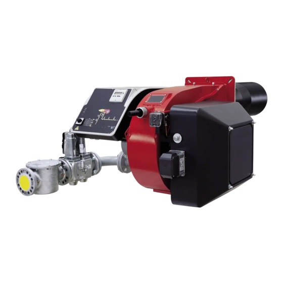
Burner data plate Type Gas - Light oil burners For the following information, please refer to Model Year European Directives the data plate: S.Number -Regulation 2016/426/UE (appliances burning gaseous fuels) burner type and burner model: must be Output Oil Flow -2014/35/UE (Low Tension Directive) reported in any communication with the Fuel... - Page 5 PART I: SPECIFICATIONS PART I: SPECIFICATIONS BURNERS FEATURES Note: the figure is indicative only Control panel with startup switch Combustion head adjusting ring nut Electrical panel Cover Blast tube + Combustion head Flange Actuator Silencer Gas train 10 Pump motor 11 Fan motor 12 Photocell 13 Air pressure switch...
-
Page 6: Burner Model Identification
Burners are identified by burner type and model. Burner model identification is described as follows. Type G380A Model PR. SR. 1 BURNER TYPE G258A, G335A, G380A, G400A MG - Natural gas-Light oil 2 FUEL LG - LPG - Light fuel oil 3 OPERATION (Available versions) PR - Progressive, MD - Fully modulating... -
Page 7: Technical Specifications
PART I: SPECIFICATIONS Technical Specifications BURNER TYPE G258A G335A G380A G400A 165 - 2580 280 - 3350 295 - 3800 580 - 4000 Output min. - max. kW Fuel MG - Natural gas-Light oil (see next paragraph) Category 17,5 - 273... - Page 8 G400A 1496 1139 G400A 1496 1385 G400A 1496 1416 1002 G400A 1496 1499 1085 B*: SPECIAL blast tube lengths must be agreed with Cib Unigas BS = standard blast tube BL = long blast tube DN = gas valves size...
- Page 9 3I2MG-21 v0 Hydraulic diagram LEGEND POS OIL TRAIN Filter Flexible hose Pump and pressure governor oil inlet Electrical motor Solenoid valve Solenoid valve Oil distributor oil outlet Pressure gauge Pressure governor Pressure switch One-way valve 16.1 One-way valve 16.1 Flexible hose Manual valve Pressure gauge combustion air...
-
Page 10: Performance Curves
This value must be lower or equal to the pgas value, calcula- ted before. Power kW Potenza / Output (kW) Performance Curves G258A MG G335A MG G380A MG G400A MG To get the input in kcal/h, multiply value in kW by 860. - Page 11 Pressure in the Network / gas flow rate curves Performance Curves G258A MG G335A MG G380A MG G400A MG ATTENTION: the gas rate value is quoted on the x-axis, the related network pressure is quoted on the y-axis (pressure value in the combustion chamber is not included). To know the minimum pressure at the gas train inlet, necessary to get the requested gas rate, add the pressure value in the combustion chamber to the value read on the y-axis.
- Page 12 PART I: SPECIFICATIONS Combustion head gas pressure curves Combustion head gas pressure depends on gas flow and combustion chamber backpressure. When backpressure is subtracted, i depends only on gas flow, provided combustion is properly adjusted, flue gases residual O2 percentage complies with “Recommended combustion values”...
- Page 13 PART I: SPECIFICATIONS Gas pressure burner head vs natural gas flow rate Curves are referred to pressure = 0 mbar in the combustion chamber! G258A M- G335A M- G380A M- G400A M-...
- Page 14 PART II: INSTALLATION PART II: INSTALLATION MOUNTING AND CONNECTING THE BURNER Transport and storage If the product must be stored, avoid humid and corrosive places. Observe the temperatures stated in the burner data table at the begin- ning of this manual. The packages containing the burners must be locked inside the means of transport in such a way as to guarantee the absence of dangerous movements and avoid any possible damage.
- Page 15 PART II: INSTALLATION Fitting the burner to the boiler To install the burner into the boiler, proceed as follows: make a hole on the closing door of the combustion chamber as described on paragraph “Overall dimensions”) place the burner to the boiler: lift it up and handle it according to the procedure described on paragraph “Handling the burner”; place the 4 stud bolts (5) on boiler’s door, according to the burner drilling template described on paragraph “Overall dimensions”;...
- Page 16 PART II: INSTALLATION GAS TRAIN CONNECTIONS The diagrams show the components of the gas train included in the delivery and which must be fitted by the installer.The diagrams are in compliance with the current laws. Note: the figure is indicative only ”direction”...
-
Page 17: Mounting Positions
PART II: INSTALLATION 4 Proving system pressure switch - PGCP 9 Antivibration joint (*optional) 5 Pressure switch PGMAX: mandatory for MBE, optional for VGD and MB-DLE 10 Manual valve(*optional) MultiBloc MB-DLE - Assembling the gas train MULTIBLOC DUNGS Mounting Mount flange onto tube lines: use appropriate sealing agent MB-DLE 405..412 Insert MB-DLE: note position of O rings MB-DLE 415..420... - Page 18 PART II: INSTALLATION MultiBloc MBE Example of gas train MBE 501939 GAS BRUCIATORE ø185 VD-R VD-V VD-R VD-V Gas filter PGMAX PGMAX PGMI PGMIN PS pressure sensor PGCP PGCP ATTENTION: once the gas train is mounted according, the gas proving test mus be performed, according to the procedure set by the laws in force.
- Page 19 PART II: INSTALLATION Siemens VGD20.. e VGD40.. Siemens VGD20.. and VGD40.. gas valves - with SKP2.. (pressure governor) - Connect the reference gas pipe (TP in figure; 8mm-external size pipe supplied loose), to the gas pressure nipples placed on the gas pipe, downstream the gas valves: gas pressure must be measured at a distance that must be at least 5 times the pipe size.
-
Page 20: Overall Dimensions (Mm)
PART II: INSTALLATION Siemens VGD SKPx5 (Auxiliary-optional micro switch) Actuator connection Valve drive End of stroke Plug connection Plug connection ON-OFF (only with SKPxx.xx1xx) A Valve closed Gas valveGas Filter (if provided) The gas filters remove the dust particles that are present in the gas, and prevent the elements at risk (e.g.: burner valves, counters and regulators) from becoming rapidly blocked. - Page 21 PART II: INSTALLATION BURNERS WITH INVERTER VARIANT (if provided) Type Model XXXXX M-. MD. xx. xx. x. x. xxx. EI. XXXXX M-. MD. xx. xx. x. x. xxx. EG. LMV5 DANFOSS XXXXX MG. MD. xx. xx. x. x. xxx. EK. XXXXX MG.
- Page 22 PART II: INSTALLATION BURNERS WITH INVERTER VARIANT (if provided) KOSTAL Tipo Modello XXXXX M-. MD. xx. xx. x. x. xxx. EI. XXXXX M-. MD. xx. xx. x. x. xxx. EG. LMV5 XXXXX MG. MD. xx. xx. x. x. xxx. EK. XXXXX MG.
- Page 23 PART II: INSTALLATION Integrated proving system (burners equipped with LME7x, LMV, LDU) This paragraph describes the integrated proving system operation sequence: At the beginning both the valves (EV1 and EV2) must be closed. Test space evacuating: EV2 valve (burner side) opens and keep this position for a preset ...
- Page 24 PART II: INSTALLATION Installation diagram of light oil pipes please read carefully the “warnings” chapter at the beginning of this manual. Fig. 4 - Double-pipe system The burner is supplied with filter and flexible hoses, all the parts upstream the filter and downstream the return flexible hose, must be installed by the customer.
- Page 25 PART II: INSTALLATION About the use of fuel pumps Do not use fuel with additives to avoid the possible formation over time of compounds which may deposit between the gear teeth, thus obstructing them. After filling the tank, wait before starting the burner. This will give any suspended impurities time to deposit on the bottom of the ...
- Page 26 PART II: INSTALLATION Suntec TA.. Oil viscosity 3 ÷ 75 cSt Oil temperature 0 ÷ 150°C Min. suction pressure - 0.45 bar to avoid gasing Max. suction pressure 5 bar Max. return pressure 5 bar Rotation speed 3600 rpm max. 1.
-
Page 27: Electrical Connections
PART II: INSTALLATION ELECTRICAL CONNECTIONS WARNING: (only for double stage and progressive burners) The burner is provided with an electrical bridge between terminals 6 and 7; when connecting the high/low flame thermostat, remove this bridge before connecting the thermostat. Any cable connection or hook-up to the grid must be carried out by qualified, informed and trained personnel, directly coordinated and authorized by Technical Service. - Page 28 PART II: INSTALLATION Siemens CD attached to the burner C - Capacitor (22 nF , 250 V) LMV2/3... - LMV5... LME / LMV - Siemens control box R - Resistor (1 MΩ) M: Terminal 2 (LGB, LME), Terminal X3-04-4 ( LMV2x, LMV3x, LMV5, LME7x) RC466890660 - RC Siemens filter Configuration with separate electrical panel (optional)
- Page 29 PART III: OPERATION PART III: OPERATION IN THE EVENT OF A BLOCKAGE, THE CAUSE MUST BE ASSESSED. IF THE FLAME BACKFIRE WARNING LIGHT IS ON, IT IS IMPERATIVE TO CHECK THE INTEGRITY AND GOOD CONDITION OF THE COMBUSTION HEAD AS DESCRIBED IN THE MAINTENANCE SECTION BEFORE UNLOCKING THE APPLIANCE.
-
Page 30: Fuel Selection
PART III: OPERATION Keys B1 Lock-out LED B2 Hi-flame operation LED B4 B5 B3 Lo-flame operation LED B4 “Ignition transformer operation” LEDG1“EV2 opening” LED B2 B3 G2 “EV1 opening” LED G3 “Gas pressure switch signal ” LED G4 Gas proving system lockout signalling LED S4 Fuel selection S7 CMF switch 0=stop 1=high flame2=low flame 3=automatic-fully modulating burnersonlyO1EVG1... - Page 31 PART III: OPERATION AIR FLOW AND FUEL ADJUSTMENT WARNING! During commissioning operations, do not let the burner operate with insufficient air flow (danger of formation of carbon monoxide); if this should happen, make the fuel decrease slowly until the normal combustion values are achieved.
-
Page 32: User Interface
PART III: OPERATION Drive the burner to high flame stage (please refer to the LMVx documentation attached to this manual). User interface The AZL2x.. display is shown below: The keys functions are the following: Service mode Info mode Parametere setting mode Plant heat request Oil pre-heater energised Fan motor energised... - Page 33 PART III: OPERATION The accesses to the various blocks are allowed by passwords. Passwords are divided into three levels: User level (info): no password needed Service level (Service) Manifacturer level (OEM) PHASES LIST During operation, the following program phases are shown. The meaning for each phase is quoted in the table below Fase / Funzione Function...
-
Page 34: Info Level
PART III: OPERATION By means of a proper use of the keys, it is possible to enter the various level parameters, as shown in the following flow chart: Basic display Service Level Automatic return after menu use time-out (parameter 127) Info level Parameter Level Switching to the basic display... - Page 35 PART III: OPERATION press InFo for 1-3 seconds: the date will appear press InFo to go back to parameter “102” by pressing + / -, it is possible to scroll up/down the parameter list (see table above), or, by pressing ESC or InFo for more seconds, the display will show Once the last parameter is accessed (143) by pressing + , the End message will flash.
-
Page 36: Parameter Description
PART III: OPERATION To reset, press InFo for a second. Record the codes and check the Error List to find the type of faults. Service level To enter the Service mode, press InFo until the display will show: The service level shows all the information about flame intensity, actuators position, number and lock codes: Parameter Description Flame intensity... - Page 37 PART III: OPERATION Adjustment procedure for light oil operation The light oil flow rate can be adjusted choosing a by-pass nozzle that suits the boiler/utilisation output and setting the delivery and return pressure values according to the ones quoted on the table below and the diagram on Fig. 20 (as far as reading the pressure values, see next paragraphs).
- Page 38 PART III: OPERATION FLUIDICS KW3...60° NOZZLE SUPPLY PRESSURE = 20 bar. VISCOSITY AT NOZZLE = 5 cSt The nominal size of the nozzle is indicated at the ends of the curve Pressure on return (bar)
- Page 39 PART III: OPERATION FLUIDICS KW3...60° NOZZLE SUPPLY PRESSURE = 20 bar. VISCOSITY AT NOZZLE = 5 cS The nominal size of the nozzle is indicated at the ends of the curve Pressure on return (bar) The nominal size of the nozzle is indicated at the ends of the curve Pressure on return (bar)
- Page 40 PART III: OPERATION FLUIDICS KW3...60° NOZZLE SUPPLY PRESSURE = 20 bar. VISCOSITY AT NOZZLE = 5 cSt The nominal size of the nozzle is indicated at the ends of the curve Pressure on return (bar) The nominal size of the nozzle is indicated at the ends of the curve Pressure on return (bar) The nominal size of the nozzle is indicated at the ends of the...
- Page 41 PART III: OPERATION REGULATION: Multibloc MB-DLE VS T(VR) The multibloc unit is a compact unit consisting of two valves, gas pressure switch, pres- sure stabilizer and gas filter. The valve is adjusted by means of the RP regulator after slackening the locking screw VB by a number of turns.
-
Page 42: Pressure Taps
PART III: OPERATION MultiBloc MBE Regulation VD-R whith PS Setting scale is „Not“ linear! Various sensors available. Output pressure according to sensor‘s measuring range. Increasing pressure Adjust the outlet pressure to the value specified by the burner or equipment manufacturer! Decreasing pressure While making outlet pressure adjustments, do not exceed a value that creates a hazardous condition to the... - Page 43 PART III: OPERATION Calibration air and gas pressure switches The air pressure switch locks the control box if the air pressure is not the one requested. If it happens, unlock the burner by means of the control box unlock pushbutton, placed on the bur- ner control panel.
- Page 44 PART III: OPERATION HEAD ADJUSTING Regulating the combustion head The burner is factory-adjusted with the combustion head in the "MAX" position, accordingly to the maximum power. To operate the bur- ner at a lower power, progressively shift back the combustion head, towards the "MIN" position, screwing the screw VRT. The ID index shows how much the combustion head moved.
-
Page 45: Routine Maintenance
PART IV: MAINTENANCE PART IV: MAINTENANCE At least once a year carry out the maintenance operations listed below. In the case of seasonal servicing, it is recommended to carry out the maintenance at the end of each heating season; in the case of continuous operation the maintenance is carried out every 6 months. - Page 46 PART IV: MAINTENANCE Gas filter maintenance To clean or remove the filter, proceed as follows: 1 remove the cap unscrewing the fixing screws (A); 2 remove the filtering cartridge (B), clean it using water and soap, blow it with compressed air(or replace it, if necessary) 3 replace the cartridge in its proper position taking care to place it inbetween the guides as not to hamper the cap replacement;...
- Page 47 PART IV: MAINTENANCE MultiBloc MBE MultiBloc VD Mounting to push position 1. Position VD on VB, fig. 2+3. 2. Slide VD forward up to the stop, fig. 4. 3. Screw VD on with 2 M5 screws for each, max. 5 Nm/44 in.-lb., fig. 5/6. 4.
-
Page 48: Electrodes Adjustment
PART IV: MAINTENANCE Electrodes Adjustment Adjust the electrodes position, according to the quotes shown othe next picture A = 4 B = 8 ATTENTION: avoid the ignition and detection electrodes to contact metallic parts (blast tube, head, etc.), otherwise the boiler’s operation would be compromised. - Page 49 PART IV: MAINTENANCE To remove the oil gun, proceed as follows: remove the combustion head as described on the prevoius paragraph; loosen the VL screw and remove the oil gun and the electrodes: check the oil gun, replace it if necessary; after removing the oil gun, unscrew the nozzle and replace it if necessary;...
-
Page 50: Seasonal Stop
PART IV: MAINTENANCE Checking the detection current To check the detection signal follow the scheme in the picture below. If the signal is less than the value indicated, check the position of the detection electrode or detector, the electrical contacts and, if necessary, replace the electrode or the detector. Device Flame detector Minimum detection signal... - Page 51 PART IV: MAINTENANCE TROUBLESHOOTING GUIDE Gas operation * No electric power supply * Restore power supply * Main switch open * Close switch * Thermostats open * Check set points and thermostat connections * Bad thermostat set point or broken thermostat * Reset or replace the thermostat * No gas pressure * Restore gas pressure...
- Page 52 PART IV: MAINTENANCE TROUBLESHOOTNG GUIDE Light oil operation * No electric power supply * Wait for electric power supply is back * Main switch open * Close the switch * Thermostats open * Check set points and thermostat connections * Bad thermostat set point or broken thermostat * Set or replace the thermostat * No gas pressure * Restore gas pressure...
- Page 56 C.I.B. UNIGAS S.p.A. Via L.Galvani, 9 - 35011 Campodarsego (PD) - ITALY Tel. +39 049 9200944 - Fax +39 049 9200945/9201269 web site: www.cibunigas.it - e-mail: cibunigas@cibunigas.it Note: specifications and data subject to change. Errors and omissions excepted.
- Page 57 AZL2x - LMV2x/3x Burner Management System Service manual 03/2023 M12916CD Rev. 3.4...
- Page 58 INDEX MICROPROCESSOR CONTROLLED SYSTEM..........................6 User interface....................................6 Parameters level (heating engineer)............................... 8 Setting menu....................................9 Block 000: Internal Parameter ..............................10 Block 100: General information..............................10 Block 200: Burner control................................13 Block 400: Setting air/fuel ratio curves............................25 Block 500: Air/fuel ratio control ..............................26 Block 600: Actuators ..................................
-
Page 59: Special Warnings
DANGERS, WARNINGS AND NOTES OF CAUTION THIS MANUAL IS SUPPLIED AS AN INTEGRAL AND ESSENTIAL PART OF THE PRODUCT AND MUST BE DELIVERED TO THE USER. INFORMATION INCLUDED IN THIS SECTION ARE DEDICATED BOTH TO THE USER AND TO PERSONNEL FOLLOWING PRO- DUCT INSTALLATION AND MAINTENANCE. - Page 60 DIRECTIVES AND STANDARDS do not leave the equipment exposed to weather (rain, sun, etc.) unless expressly required to do so; Gas burners European directives: do not allow children or inexperienced persons to use equipment; - Directive 2009/142/EC - Gas Appliances; The unit input cable shall not be replaced by the user.
-
Page 61: National Standards
-EN 55014-1Electromagnetic compatibility - Requirements for household appliances, electric tools and similar apparatus. -UNI EN 676 (Gas Burners; -CEI EN 60335-1(Household and similar electrical appliances - Safety. Part 1: General requirements; - EN 50165 Electrical equipment of non-electric appliances for household and similar purposes. - Page 62 MICROPROCESSOR CONTROLLED SYSTEM The control system is made of the Siemens LMV central unit that performs all the burner control functions and of the Siemens AZL local programming unit that interfaces the system with the user. Keys Burner AZL2.. Air actuator Fuel actuator LMV2..
- Page 63 The keys functions are the following: Key F Used to adjust the “fuel” actuator position (Fuel): : While pressing the F key, the “fuel” actuator position can be changed by means of the + and - keys. Key A Used to adjust the “air” actuator position (Air): While pressing the A key, the “air”...
- Page 64 Parameters level (heating engineer)
- Page 65 Setting menu The seeting menu is divided into different blocks: Bloc. Descrizione Description Password Internal parameters OEM / Service Informazioni generali General OEM / Service / Info Controllo bruciatore Burner control OEM / Service Controllo bruciatore (solo LMV26) Burner control (LMV26 only) OEM / Service Curve rapporto Ratio curves...
- Page 66 Block 000: Internal Parameter Param. Descrizione Description Password Password livello assistenza (ingegnere del Password heating engineer (4 characters) calore) Password livello OEM (costruttore del brucia- Password OEM (5 characters) tore) Start backup / restore via AZL2.../ PC sof- tware (set parameter to 1) Index 0: Create backup Index 1: Execute restore Error dia- Start backup/restore via AZL2x/PC gnostics via negative values...
- Page 67 Frequenza di rete Mains frequency 0 = 50 Hz 0 = 50 Hz Service / Info 1 = 60 Hz 1 = 60 Hz Luminosità display Display brightness Service / Info Tempo dopo il quale, se non viene premuto nessun tast il software esce dalla modalita Timeout for menu operation (default value = programmazione (valore fabbrica = 60min - 60min - range: 10 - 120 min)
- Page 68 Numero totale di partenze (non azzerabile) Total number of startups Service / Info Volume combustibile (azzerabile da OEM) Fuel volume (resettable by OEM) Service / Info Fuel 1(secondo combustibile)Ore di eserci- Fuel 1: Operation hours resettable Service / Info zio (azzerabile da Service) Fuel 1 (secondo combustibile) Numero di Fuel 1: Number of startups resettable Service / Info...
- Page 69 Block 200: Burner control Param. Descrizione Description Password Modalità funzionamento bruciatore ( rampa Burner operating mode (fuel train, modula- combustibile, modulante / multistadio, servo- ting / multistage, actuators, etc..) comandi, ecc.) __= non definito (cancellazione curve) __= undefined (delete curves) 1 = accensione diretta a gas (G mod) 1 = gas direct ignition (G mod) 2 = accensione tramite pilota gas con attacco...
- Page 70 15 = gas rampa Gp1 modulante pneumatico 15 = Gp1 mod pneu without actuator senza servomotori (Gp1 mod pneu) 16 = Gp2 mod pneu without actuator 16 = gas rampa Gp2 modulante pneumatico 17 = Lo 2-stage without actuator senza servomotori (Gp2 mod pneu) 18 = Lo 3-stage without actuator 17 = olio LO 2 stadi senza servomotori 19 = G mod gas actuator only...
- Page 71 Gas: sonda rilevazione fiamma attivo (valore Gas: active detector flame evaluation (default fabbrica = 1) value = 1) OEM / Service 0 = QRB../QRC.. 1 = ION / QRA.. Gas: Preventilazione (valore fabbrica = 1) Gas: Pre-purging (default value = 1) 1 = attivo 1 = active 0 = non attivo...
- Page 72 Gas: Pressostato gas di minima (default = 1) Gas: Pressure switch-min input 0 = inattivo 0 = inactive 1 = pressostato gas di minima (a monte val- 1 = pressure switch-min (upstream of fuel vola V1) valve 1 (V1)) 2 = controllo perditavalvole via pressostato 2 = valve proving via pressure switch-min OEM / Service (montato tra le valvole V1 e V2)
- Page 73 Gas: tempo pressione atmosferica controllo Gas: proving test time atmospheric pres- tenuta (valore fabbrica = 10s - range impo- sure (default value = 10s - range:0.2s - 60s) stazione:0.2s - 60s) Gas: tempo riempimento controllo tenuta Gas: proving test filling time (default value = (valore fabbrica = 3s - range imposta- 3s - range:0.2s - 10s) zione:0.2s - 10s)
- Page 74 Olio: Intervallo 1 (valore fabbrica = 2s - Oil: Interval 1 (default value = 2s - OEM / Service range impostazione:0.2s - 60min) range:0.2s - 60min) Olio: tempo di sicurezza 2 (TSA2) (valore Oil: safety time 2 (TSA2) (default value = 3s fabbrica = 3s - range impostazione:0.2 - 10s) - range:0.2 - 10s) Olio: Intervallo 2 (valore fabbrica = 2s -...
- Page 75 Block 300: Burner control (only with LMV26) Param. Descrizione Description Password Combustibile 1 : Modalità funzionamento bru- Fuel 1 : Burner operating mode (fuel train, ciatore ( rampa combustibile, modulante / modulating / multistage, actuators, etc..) multistadio, servocomandi, ecc.) __= non definito (cancellazione curve) __= undefined (delete curves) 1 = accensione diretta a gas (G mod) 1 = gas direct ignition (G mod)
- Page 76 11 = olio 2 stadi con accensione tramite pilota 11 = LoGp 2-stage (LOGp 2-stage) 12 = Lo mod 2 fuel valves 12 = olio modulante con 2 valvole combusti- 13 = LoGp mod 2 fuel valves bile (LOmod 2 valvole) 14 = G mod pneu without actuator 13 = olio modulante con 2 valvole combusti- 15 = Gp1 mod pneu without actuator...
- Page 77 Combustibile 1 - Gas: tempo di preaccen- Fuel 1 - Gas: Preignition time (default value = sione (valore fabbrica = 2s - range imposta- 2s - range: 0.2s - 60min) OEM / Service zione:0.2s - 60min) Combustibile 1 - Gas: tempo di sicurezza 1 Fuel 1 - Gas: Safety time 1 (TSA1) (default (TSA1) (valore fabbrica = 3s - range impo- value = 3s - range: 0.2 - 10s)
- Page 78 Limite ripetizioni perdita di fiamma (valore Repetition limit loss of flame (default value= 2 fabbrica = 2 - range impostazione:1 - 2) - range:1 - 2) Fuel 1 - Gas: execution proving test (default Combustibile 1 - Gas: esecuzione controllo value= 2) tenuta (valore fabbrica = 2) 0 = no controllo tenuta...
- Page 79 Fuel 1 - Oil: prepurging (default value = 1) Combustibile 1 - Olio: preventilazione (valore fabbrica = 1) 0 = deactivated 1 = attivo 1 = activated 0 = non attivo 0 = deactivated OEM / Service In ambito civile la norma EN267 rende obbli- WARNING: in the civil field, the prepurge is gatoria la preventilazione.
- Page 80 Limite ripetizioni perdita di fiamma (valore Repetition limit value loss of flame (default fabbrica = 2 - range impostazione:1 - 2) value = 2 - range:1 - 2) Fuel 1 - Oil: time oil ignition (default value = Combustibile 1 - Olio: tempo iniezione olio (valore fabbr.
- Page 81 Block 400: Setting air/fuel ratio curves Param. Descrizione Description Password Curve controllo servocomando combustibile Ratio control curve fuel actuator (F): it acces- (F): si accede alla lista dei punti da impostare ses to the parameter list of the points to be set OEM / Service (da P0 a P9) - consultare paragrafo “Imposta- (P0 to P9) - see paragrapf “Setting the curves”...
- Page 82 Block 500: Air/fuel ratio control Param. Descrizione Description Password No-flame position fuel actuator Posizione servocomando combustibile in assenza di fiamma (no-flame) Indice 0 = posizione di sosta = 0° Index 0 = no-load position = 0° OEM / Service Indice 1 = posizione preventilazione = 0° Index 1 = prepurge position = 0°...
- Page 83 Activation of VSD / PWM fan (PWM = Pulse- Width Modulation) Activation of VSD / PWM fan OEM / Service 0=deactived 1=actived (PWM = Pulse-Width Modulation) Parameter 544 Modulation Modulation Modulation Modulation Actuator Actuating speed param- Max. delta between the curve points eter 613 OEM / Service Actuator...
- Page 84 Block 600: Actuators Param. Descrizione Description Password Impostazione punto di riferimento Selection of reference point Indice 0 = combustibile Index 0 = fuel Indice 1 = aria Index 1 = air 0 = chiuso (<0°) 0 = closed (<0°) 1 = aperto (>90°) 1 = open (>90°) Direzione rotazione del servocomando Actuator’s direction of rotation...
- Page 85 Tipo di riferimento dei servocomandi index 0 = fuel (default = 0 (riferimento stan- dard) Type of referencing index 1 = air (default = 0 (riferimento stan- Index 0 = fuel dard) Index 1 = air 0 = standard 0 = standard 1 = fermo entro il raggio utile 1 = stop within usable range 2 = fermi interni (SQN1...)
- Page 86 Configurazione uscita analogica % di carico Configuration of analog output (default value (valore fabbrica = 0) = 0) 0 = DC 0..10 V 0 = DC 0..10 V OEM / Service 1 = DC 2..10 V 1 = DC 2..10 V 2 = DC 0/2..10 V 2 = DC 0/2..10 V ATTENTION: as for SQM3x actuators, set the direction according to the acutator function.
- Page 87 Block 700: Error history Param. Descrizione Description Password Storico errori: 701 - 725.01.codice Error history: 701 - 725.01.code Service / Info Storico errori: 701 - 725.02.codice diagnostico Error history: 701 - 725.02.diagnostic code ° Service / Info Storico errori: 701 - 725.03.classe errore Error history: 701 - 725.03.error class °...
- Page 88 Block 900: Process data Param. Descrizione Description Password Potenza attuale (valore fabbrica = 0% - range Current output (default value = 0% - range = impostazione = 0-100%) 0-100%) Service / Info Indice 0 = combustibile Index 0 = fuel Indice 1 = aria Index 1 = air Posizione incrementale servocomandi (valore...
- Page 89 Actuators references An incremental transducer is used to ensure position feedback. Referencing of the actuators must be performed after power-on. In addition, at the end of each shutdown in phase 10, the actuators are referenced to ensure that individual stepping errors, which could lead to shutdown, do not accumulate.
-
Page 90: Commissioning The Burner
COMMISSIONING THE BURNER The LMV2x complete programming must be performed on units that has never been set before or reset units (e.g. spare parts). The programming procedure is performed by setting the following main parameters: if LMV.. is a spare part, insert burner ID (parameter 113) at least 4 digit. type of fuel train (parameter “201”) air/fuel ratio curvepoints (Block “400”) maximum load percentage (parameter “546”) - Page 91 the types of fuel trains are the following: Param. Descrizione Description Password Modalità funzionamento bruciatore ( rampa Burner operating mode (fuel train, mod / multi- comb., mod. / multistadio, servocom., ecc.) stage, actuators, etc.) __= non definito (cancellazione curve)___= __= undefined (delete curves) 1 = accensione diretta a gas (G mod) 1 = gas direct ignition(G mod) 2 = accensione tramite pilota gas con attacco...
- Page 92 Lo 3-stage In the example the Gmod gas train has been set (Configuration “1”). Choose the fuel train by pressing ENTER, then press “+” / “-”. Press ENTER to confirm: number “1” will appear on the right side of the display.
- Page 93 CAUTION: at the first burner adjustment, it is recommended to set the maximum output P9 at the same value (or little higher) of the ignition point, in order to safely reach point P9 next (see next paragraph). By pressing “+” the display will show: The burner is ready to startup.
-
Page 94: Warm Setting
Warm setting Once pressed button “enter” and the chain thermostats open (X5-03 terminals), the LMV.. show Ph12.Then close the chain termostat and the unit performs the prepurge cycle (see “Phases List”) and stops at the ignition point P0 without ignition anyway. By pressing “+”, the burners lights abd the air/fuel ratio can be properly set in presence of flame. -
Page 95: Cold Setting
P5, keep pressing “-” unitl “Calc” is displayed. The curve will be processed again downwards point P1. Fuel deviation between two following points: 25°max. 12 press “-” to go through the lower points and check the combustion values, if necessary change the points as described above. 13 By pressing ESC, at the end of the points adjusments, the parameter “546”... - Page 96 BURNER STARTUP WITH LMV2x ALREADY PROGRAMMED Once the LMV turns on, the AZL display will show The burners is basically factory set. The air/fuel ratio curve is set with the maximum output point P9 a little higher or equal to P0. To adjust the burner on the plant site, adjust the maximum output point to the flow rate values really requested.
- Page 97 Set the air/fuel ratio curvepoints as described on chapter “Programming the LMV2x” Note: the other phases are Ph60 = operation (OP= in modulation) Ph62 = travelling to shutdown Ph70 = off but in prepurge after the burntime Ph72 = travelling to postpurging Ph74 = postpurge (countdown is displayed) Press ESC the parameter “546”...
- Page 98 Reset / manual lockout The system can be manually locked by simultaneously pressing the ENTER (InFo) button and any other button on the AZL2..This function allows the user to stop the system from the operating level should an emergency occur. When making a reset, the following actions are carried out: Alarm relay and the fault display are off ...
- Page 99 Entering the Parameter levels By means of a proper use of the keys, it is possible to enter the various level parameters, as shown in the following flow chart: The burner and consequently the LMV2x.. are factory set; the air and fuel curves as set as well.
- Page 100 Info level To enter the Info level, proceed as follows: in any menu position, press keys + and - at the same time, then the program will start again: the display will show OFF. , until the display will show InFo, Press the enter (InFo) key then il will show the first code (167) flashing, on the right side it will show the data entered.
- Page 101 10 Press InFo for more than three seconds or for more than three seconds orto return to the normal display. If a message like the one below is shown during operation, it means that the burner is locked out and the Errore code is shown (in the example “error code:4”); this message is alternating with another message Diagnostic code (in the example “diagnostic code:3”).
-
Page 102: Service Level
Service level To enter the Service mode, press InFo until the display will show: The service level shows all the information about flame intensity, actuators position, number and lock codes: Parameter Description Flame intensity % output, if set = automatic operation Actuators position, 00=combustibile;... - Page 103 PHASES LIST Fase /Phase Funzione Function Ph00 Fase blocco Lockout phase Ph01 Fase di sicurezza Safety phase Ph10 t10 = tempo raggiungimento posizione riposo t10 = home run Ph12 Pausa Standby (stationary) t22 = tempo di salita ventilatore (motore ventilatore t22 = fan ramp up time (fan motor = ON, safety Ph22 = ON, valvola intercettazione di sicurezza = ON)
- Page 104 BACKUP PARAMETER WITH AZL2x On the AZL2x you can save the configuration to download on another appliance LMV. To do this: access up, press F and A at the same time enter the password following the procedure on chapter “Programming LMV2x”. Press ENTER until the display will show: with the button go to the group 000 of the parameters and press...
- Page 105 RESTORE PARAMETER FROM AZL2x TO LMV.. To copy the previously saved configuration on AZL2x proceed as follows: access up, press F and A at the same time enter the password following the procedure on chapter “Programming LMV2x”. Press ENTER until the display will show: To copy the configuration from AZL2x to LMV.
- Page 106 ERROR CODE TABLE...
- Page 121 WIRING DIAGRAM Wiring connection for LMV20 Electrical supply Burner flange Fanmotor input Safety loop Lokout signal Continuous fan operator Valve External valveSV gnition transformer Valve Operation sgnal Reset Reserve Common Increase output Pressure switch leakage test Decrease input gasPGCP ON/OFF thermosta Minimum gas pressure switch Air pressure switch LUFT...
- Page 122 Wiring variants for LMV27 ConnectorX75 2 - Fuel meter input 1 - Supply fuel meter ConnectorX5-02 ConnectionsPmax...
- Page 123 Wiring variants for LMV26 ConnectorX08-04 / X09-04 2 - Fuel 0 1 - Fuel1 ConnectorX75 2 - Fuel meter input 1 - Supply fuel meter ConnectorX64 5 -Power supply speed sensor 4 -Speed sensor input 3 - PWM (Pulse Width Modulation) speed output 2 - GND (signal reference) 1 -Controller input (4÷20mA) ConnectorX74...
- Page 124 Wiring variants for LMV37 ConnectorX75 2 - Fuel meter input 1 - Supply fuel meter ConnectorX5-02 Connections Pmax ConnectorX64 5 -Power supply speed sensor 4 -Speed sensor input 3 - PWM (Pulse Width Modulation) speed output 2 - GND (signal reference) 1 -Controller input (4÷20mA) ConnectorX74 5 -Supply...
- Page 128 C.I.B. UNIGAS S.p.A. Via L.Galvani, 9 - 35011 Campodarsego (PD) - ITALY Tel. +39 049 9200944 - Fax +39 049 9200945/9201269 web site: www.cibunigas.it - e-mail: cibunigas@cibunigas.it Note: Specifications and and data subject to change. Errors and omissions excepted.
Need help?
Do you have a question about the G335A and is the answer not in the manual?
Questions and answers