
Related Manuals for Unigas R91A


Summary of Contents for Unigas R91A
-
Page 1: Gas Burners
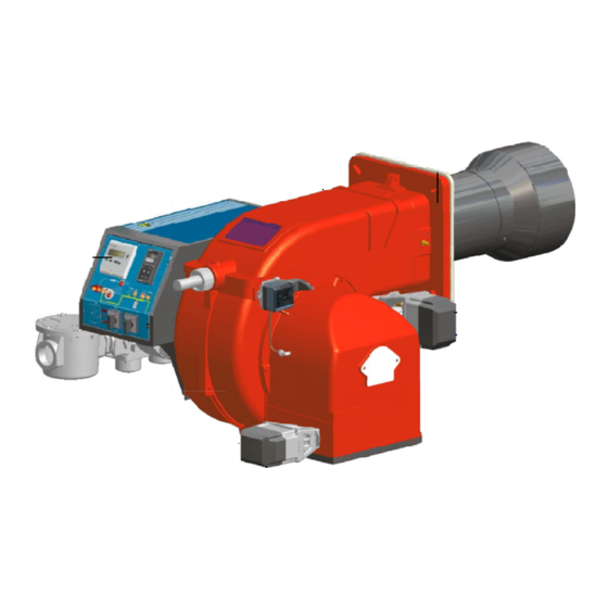
R91A R92A R93A Microprocessor-controlled gas burners MANUAL OF INSTALLATION - USE - MAINTENANCE BURNERS - BRUCIATORI - BRULERS - BRENNER - QUEMADORES - M039231CB Rel.1.0 05/2010... -
Page 2: Table Of Contents
TABLE OF CONTENTS WARNINGS ................................3 PART I: INSTALLATION MANUAL .......................... 5 GENERAL FEATURES ................................... 5 How to interpret the burner’s “Performance curve” ......................... 7 BURNER FEATURES..................................8 Technical Specifications ................................. 8 Country and usefulness gas categories ............................8 Overall dimensions ..................................9 Pressure in the Network / gas flow rate curves .......................... -
Page 3: Warnings
WARNINGS THIS MANUAL IS SUPPLIED AS AN INTEGRAL AND ESSENTIAL PART OF THE PRODUCT AND MUST BE DELIVERED TO THE USER. INFORMATION INCLUDED IN THIS SECTION ARE DEDICATED BOTH TO THE USER AND TO PERSONNEL FOLLOWING PRO- DUCT INSTALLATION AND MAINTENANCE. THE USER WILL FIND FURTHER INFORMATION ABOUT OPERATING AND USE RESTRICTIONS, IN THE SECOND SECTION OF THIS MANUAL. - Page 4 DIRECTIVES AND STANDARDS 3b) FIRING WITH GAS, LIGHT OIL OR OTHER FUELS Gas burners GENERAL European directives: The burner shall be installed by qualified personnel and in com- - Directive 2009/142/EC - Gas Appliances; pliance with regulations and provisions in force; wrong installation Directive 2006/95/EC on low voltage;...
-
Page 5: Part I: Installation Manual
C.I.B. UNIGAS - M039231CB PART I: INSTALLATION MANUAL GENERAL FEATURES The control system is made of the Siemens LMV central unit that performs all the burner control functions and of the Siemens AZL local programming unit that interfaces the system with the user. - Page 6 C.I.B. UNIGAS - M039231CB Control panel with startup switch RWF Regulating modulator (only for fully--modulating burners) AZL2x user interface Gas filter Gas valves group Electrical panel Burner cover Flange Blast tube (combustion head inside) 10 Gas butterfly valve 11 Air pressure switch...
-
Page 7: How To Interpret The Burner's "Performance Curve
C.I.B. UNIGAS - M039231CB How to interpret the burner’s “Performance curve” To check if the burner is suitable for the boiler to which it must be installled, the following parameters are needed: furnace input, in kW or kcal/h (kW = kcal/h / 860);... -
Page 8: Burner Features
C.I.B. UNIGAS - M039231CB BURNERS FEATURES Burner model identification Burners are identified by burner type and model. Burner model identification is described as follows. Type R91A Model (1) BURNER TYPE R91A (2) FUEL M - Natural gas (3) OPERATION (Available versions) -
Page 9: Overall Dimensions
Overall dimensions (mm) BOILER RECOMMENDED DRILLING TEMPLATE Omin Omax R91A 1333 1159 R91A 1333 1309 R91A 1333 1311 R91A 1333 1401 R92A 1333 1159 R92A 1333 1309 R92A 1333 1311 R92A 1333 1401 R93A 1338 1159 R93A 1338 1309 R93A... -
Page 10: Pressure In The Network / Gas Flow Rate Curves
C.I.B. UNIGAS - M039231CB Performance Curves R91A R92A 1200 1600 2000 2400 2800 3200 3600 1200 1600 2000 2400 2800 R93A 1500 2500 3500 4500 To get the input in kcal/h, multiply value in kW by 860. Data are referred to standard conditions: atmospheric pressure at 1013mbar, ambient temperature at 15°C NOTE: The performance curve is a diagram that represents the burner performance in the type approval phase or in the laboratory tests, but does not represent the regulation range of the machine. -
Page 11: Mounting And Connecting The Burner
C.I.B. UNIGAS - M039231CB MOUNTING AND CONNECTING THE BURNER Packing The burners are despatched in wooden crates whose dimensions are: 1730mm x 1280mm x 1020mm (L x P x H) Packing cases of this type are affected by humidity and are not suitable for stacking. -
Page 12: Matching The Burner To The Boiler
C.I.B. UNIGAS - M039231CB The burner is designed to work positioned according to the picture below. For different installations, please contact the Technical Department. SIDE UP SIDE DOWN Matching the burner to the boiler The burners described in this manual have been tested with combustion chambers that comply with EN676 regulation and whose dimensions are described in the diagram . - Page 13 C.I.B. UNIGAS - M039231CB Gas train - 2 (Rp2) Gas train with valves group MBC 1200SE (2 valves + gas filter + pressure governor) + VPS504 gas proving system MANUFACTURER INSTALLER Gas train - 3(DN65/80/100) Gas train with valves group MBC 1900/3100/5000SE (2 valves + gas filter + pressure governor) + VPS504 gas proving system...
-
Page 14: Assembling The Gas Grain
C.I.B. UNIGAS - M039231CB Assembling the gas grain gas supply network ”direction” arrows for installation Keys 1A..1E Gasket Gas filter Gas valves group Bellows unit Manual valve Fig. 5 - Example of gas train To mount the gas train, proceed as follows: 1-a) in case of threaded joints: use proper seals according to the gas used;... -
Page 15: Siemens Vgd20
C.I.B. UNIGAS - M039231CB MULTIBLOCDUNGS MBC1900-3100-5000SE (Flanged valves group) Mounting 1. Insert setscrews A 2. Insert seals 3. Insert setscrews B 4. Tighten setscrews A + B. Ensure correct seating of the seal! 6. After installation, perform leakage and functional test. -
Page 16: Pressure Adjusting Range
C.I.B. UNIGAS - M039231CB Fig. 13 Pressure adjusting range The pressure adjusting range, downstream the gas valves group, changes according to the spring provided with the valve group. DUNGS MBC..SE Siemens SKP actuator Keys 1 spring 2 cap DUNGS MBC valves:... -
Page 17: Electrical Connections
C.I.B. UNIGAS - M039231CB ELECTRICAL CONNECTIONS Respect the basic safety rules. make sure of the connection to the earthing system. do not reverse the phase and neutral connections. fit a differential thermal magnet switch adequate for connection to the mains. -
Page 18: Adjusting Air And Gas Flow Rates
C.I.B. UNIGAS - M039231CB ADJUSTING AIR AND GAS FLOW RATES Combustion head gas pressure curves depending on the flow rate Curves are referred to pressure = 0mbar in the combustion head! The curves referred to the gas pressure in the combustion head, depending on the gas flow rate, are referred to the burner properly adjusted (percentage of residual O in the flues as shown in the “Recommended combustion values”... - Page 19 C.I.B. UNIGAS - M039231CB Pressure in combustion head - gas flow rate curves ” R91A R92A 40 60 80 100 120 140 160 180 200 220 240 260 280 300 320 340 100 120 140 160 180 200 220 240 260 280 300...
-
Page 20: User Interface
C.I.B. UNIGAS - M039231CB User interface The AZL2x.. display is shown below: h min s The keys functions are the following: Key F Used to adjust the “fuel” actuator position (Fuel): : While pressing the F key, the “fuel” actuator position can be changed by means of the + and - keys. -
Page 21: Setting Menu
C.I.B. UNIGAS - M039231CB The display will show these data:The display will show these data: Lock+unlock codes Flame Open valves Ignition transformers energised Fan motor energised Oil pre-heater energised Plant heat request Parametere setting mode Info mode Service mode h min s... -
Page 22: Phases List
C.I.B. UNIGAS - M039231CB PHASES LIST During operation, the following program phases are shown. The meaning for each phase is quoted in the table below. Phase Funzione Function Ph00 Fase blocco Lockout phase Ph01 Fase di sicurezza Safety phase Ph10... -
Page 23: Entering The Parameter Levels
C.I.B. UNIGAS - M039231CB Entering the Parameter levels By means of a proper use of the keys, it is possible to enter the various level parameters, as shown in the following flow chart: The burner and consequently the LMV2x.. are factory set; the air and fuel curves as set as well. - Page 24 C.I.B. UNIGAS - M039231CB Parameter Description Cubic meters of fule (resettable) Operating hours (resettable) Device operating hours Burners start-ups (resettable) Total number of start-ups Burner number (i.e. serial number) Software version Software date Device serial number Parameter set preassignment: Customer code...
-
Page 25: Service Level
C.I.B. UNIGAS - M039231CB another message Diagnostic code (in the example “diagnostic code:3”). Record the codes and find out the fault in the Error table. To perform the reset, press InFo for one second: The unit displays an event which does not lead to shutdown. -
Page 26: Adjusting Air And Gas Flow Rates
C.I.B. UNIGAS - M039231CB parameter list. Once the last parameter is accessed (143) by pressing + , the End message will blink. Press InFo for more than three seconds or for more than three seconds orto return to the normal display. -
Page 27: Adjusting Procedure
C.I.B. UNIGAS - M039231CB Adjusting procedure If the burner is provided with the DUNGS MBC..SE gas valves group, set the pressure regulator to 1/3 of its stroke, using a 2.5 allen key. Pressure setting go on adjusting the burner, observing the procedure on the LMV2.. related manual. -
Page 28: Adjusting The Combustion Head
C.I.B. UNIGAS - M039231CB Adjusting the combustion head CAUTION: perform these adjustments once the burner is turned off and cooled. The burner is factory-set wih the D adjusting plate holes fully open, and the combustion head at its MAX position, so it is fit to work at the maximum output. -
Page 29: Calibration Of Low Gas Pressure Switch
C.I.B. UNIGAS - M039231CB Refit the transparent plastic cover on the pressure switch. Calibration of low gas pressure switch As for the gas pressure switch calibration, proceed as follows: Remove the transparent plastic cap. While the burner is operating at the maximum output, test the gas pressure on the low gas pressure switch port. -
Page 30: Part Ii: Operation
C.I.B. UNIGAS - M039231CB PART II: OPERATION LIMITATIONS OF USE THE BURNER IS AN APPLIANCE DESIGNED AND CONSTRUCTED TO OPERATE ONLY AFTER BEING CORRECTLY CON- NECTED TO A HEAT GENERATOR (E.G. BOILER, HOT AIR GENERATOR, FURNACE, ETC.), ANY OTHER USE IS TO BE CONSI- DERED IMPROPER AND THEREFORE DANGEROUS. - Page 31 C.I.B. UNIGAS - M039231CB Main switch Lock-out light Reset pushbutton for control box Reset pushbutton for gas proving system Gas pressure switch enabling signal Lock-out light for gas proving system Hi-flame operation light Lo-flame operation light Ignition transformer operation light...
-
Page 32: Part Iii: Maintenance
C.I.B. UNIGAS - M039231CB PART III: MAINTENANCE At least once a year carry out the maintenance operations listed below. In the case of seasonal servicing, it is recommended to carry out the maintenance at the end of each heating season; in the case of continuous operation the maintenance is carried out every 6 months. -
Page 33: Replacing The Spring In The Gas Valve Group
C.I.B. UNIGAS - M039231CB Replacing the spring in the gas valve group To replace the spring in the gas valve group,proceed as follows: Carefully twist the protection cap 1 and the O-ring 2. remove the “set value” spring 3 from housing 4. -
Page 34: Adjusting The Electrodes Position
C.I.B. UNIGAS - M039231CB Adjusting the electrodes position Important Note: Check the ignition and detection electrodes after removing/adjusting the combustion head. ATTENTION: avoid the ignition and detection electrodes to contact metallic parts (blast tube, head, etc.), otherwise the bur- ner operation would be compromised. Check the electrodes position after any intervention on the combustion head. -
Page 35: Replacing The Detection Electrode
C.I.B. UNIGAS - M039231CB Replacing the detection electrode ATTENTION: avoid the ignition and detection electrodes to contact metallic parts (blast tube, head, etc.), otherwise the boi- ler’s operation would be compromised. Check the electrodes position after any intervention on the combustion head. -
Page 36: Checking The Detection Current
C.I.B. UNIGAS - M039231CB Checking the detection current To check the detection signal follow the scheme in Fig. 20. If the signal is less than the value indicated, check the position of the detec- tion electrode or detector, the electrical contacts and, if necessary, replace the electrode or the detector. -
Page 37: Spare Parts
C.I.B. UNIGAS - M039231CB SPARE PARTS Desription Code P91A P92A P93A BURNER CONTROLLER - SIEMENS LMV20 2020474 2020474 2020474 USER INTERFACE - SIEMENS AZL23 2022115 2022115 2022115 DETECTION ELECTRODE 2080107 2080107 2080107 IGNITION ELECTRODE 2080291 2080291 2080291 IGNITION ELECTRODSE 2080292... -
Page 38: Wiring Diagrams
WIRING DIAGRAMS ATTENTION: 1 - Power supply: 400V 50Hz 3N a.c. and 230V 50Hz 1N a.c. 2 - Don’t reverse phase and neutral 3 - Ensure the burner is properly earthed... - Page 55 C.I.B. UNIGAS S.p.A. Via L.Galvani, 9 - 35011 Campodarsego (PD) - ITALY Tel. +39 049 9200944 - Fax +39 049 9200945/9201269 web site: www.cibunigas.it - e-mail: cibunigas@cibunigas.it Note: Specifications and and data subject to change. Errors and omissions excepted.
Need help?
Do you have a question about the R91A and is the answer not in the manual?
Questions and answers