Unigas HR91A Manual Of Installation, Use And Maintenance
Gas / light oil dual fuel burners
Hide thumbs
Also See for HR91A:
- Manual (128 pages) ,
- Manual of installation - use - maintenance (140 pages) ,
- Manual of installation - use - maintenance (52 pages)
Advertisement
Table of Contents
- 1 General Introduction
- 2 Directives and Standards
- 3 Symbols Used
- 4 Gas Connection
- 5 Burner Type
- 6 Performance Curves
- 7 Electrical Connections
- 8 Gas Operation
- 9 Light Oil Operation
- 10 Adjustments for Gas Operation
- 11 Routine Maintenance
- 12 Electrodes Adjustment
- 13 Seasonal Stop
- 14 Wiring Diagrams
- 15 Troubleshooting
- Download this manual
Advertisement
Table of Contents

Related Manuals for Unigas HR91A


Summary of Contents for Unigas HR91A
- Page 1 HR91A - HR92A - HR93A HR512A -HR515A HR520A - HR525A Gas / light oil dual fuel burners Progressive - Fully modulating MANUAL OF INSTALLATION - USE - MAINTENANCE BURNERS - BRUCIATORI - BRULERS - BRENNER - QUEMADORES - ГОРЕЛКИ M039213CD Rel. 3.2 03/2015...
-
Page 2: General Introduction
DANGERS, WARNINGS AND NOTES OF CAUTION THIS MANUAL IS SUPPLIED AS AN INTEGRAL AND ESSENTIAL PART OF THE PRODUCT AND MUST BE DELIVERED TO THE USER. INFORMATION INCLUDED IN THIS SECTION ARE DEDICATED BOTH TO THE USER AND TO PERSONNEL FOLLOWING PRO- DUCT INSTALLATION AND MAINTENANCE. -
Page 3: Directives And Standards
DIRECTIVES AND STANDARDS do not leave the equipment exposed to weather (rain, sun, etc.) unless expressly required to do so; Gas burners European directives: do not allow children or inexperienced persons to use equipment; - Directive 2009/142/EC - Gas Appliances; The unit input cable shall not be replaced by the user. -
Page 4: Symbols Used
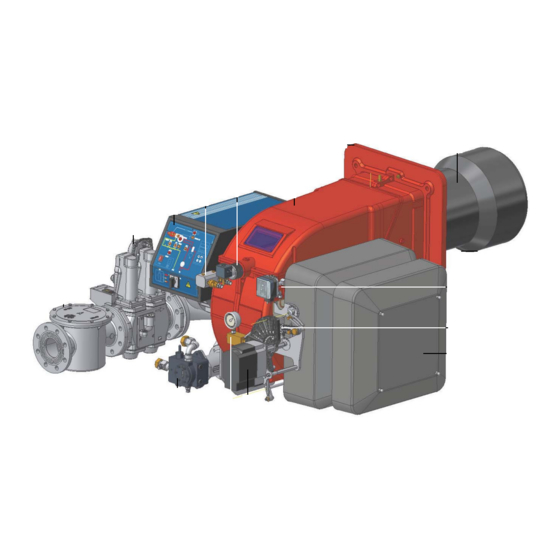
-EN 55014-1Electromagnetic compatibility - Requirements for household appliances, electric tools and similar apparatus. -UNI EN 676 (Gas Burners; -CEI EN 60335-1(Household and similar electrical appliances - Safety. Part 1: General requirements; - EN 50165 Electrical equipment of non-electric appliances for household and similar purposes. - Page 5 PART I: SPECIFICATIONS PART I: SPECIFICATIONS 1.0 BURNERS FEATURES Note: the figure is indicative only Keys 1 Mimic panel with startup switch 2 Gas filter 4 Gas valve group 5 Cover 6 Flange 7 Blast tube-Combustion head group 8 Oil pressure governor 9 Actuator 10 Adjusting cams 11 Air intake...
-
Page 6: Gas Connection
Burners are identified by burner type and model. Burner model identification is described as follows. Type HR512A Model MD. S. BURNER TYPE HR91A, HR92A, HR93A, HR512A, HR515A, HR520A, HR525A FUEL M - Natural gas L - LPG G - Light oil OPERATION (Available versions) -
Page 7: Burner Type
PART I: SPECIFICATIONS BURNER TYPE HR91A LG.. HR92A LG.. HR93A LG.. 480 - 2670 480 - 3050 550 - 4100 Output min. - max. kW L.P.G. - Light oil Fuel Category 3B/P 17.9 - 100 17.9 - 114 20 - 153 Gas rate- min.- max. - Page 8 PART I: SPECIFICATIONS HR525A...50 HR525A...xx BURNER TYPE HR512A LG.. HR515A LG.. HR520A LG.. LG.. LG.. 600 - 4500 770 - 5200 1000 - 6400 2000 - 6700 2000 - 8000 Output min. - max. kW L.P.G. - Light oil Fuel Category 3B/P 22 - 167...
- Page 9 65 1535 242 831 327 35 300 564 117 490 441 1045 421 1406 971 435 265 295 228 447 360 523 M12 424 280 300 632 148 484 846 292 708 228 185 HR91A 80 1535 242 831 327 35 300 579 132 490 441 1045 421 1437 1002 435 265 295 228 447 360 523 M12 424 280...
- Page 10 Burner flange Boiler recommended drilling tem- AC AD AE 1723 320 924 364 35 326 595 100 530 517 1193 446 1590 644 340 380 494 540 560 M14 552 390 390 763 149 614 845 190 830 307 270 1723 320 924 364 35 326 611 117 530 517 1193 446 1613 644 340 380 494 540 560 M14 552 390 390 636 149 487 845 292 830 307 270 HR512A...
- Page 11 HR91A - HR92A - HR93A Fig. 4 - 3I2MG-09 v1 Hydraulic diagram BY OTHERS LEGEND OIL TRAIN BY BURNER CONSTRUCTOR Filter Flexible hose Pump and pressure governor Electrical motor Flexible hose Solenoid valve oil inlet Solenoid valve Flexible hose oil outlet...
- Page 12 HR512A - HR515A - HR520A - HR525A Fig. 5 - 3I2MG-24 v0 Hydraulic diagram 3I2MG24 LEGEND rev.0 POS OIL TRAIN Filter Flexible hose Pump and pressure governor Electrical motor Flexible hose Solenoid valve oil inlet Flexible hose 3-way solenoid valve oil outlet Flexible hose Oil distributor...
- Page 13 PART I: SPECIFICATIONS 1.6 How to read the burner “Performance curve” To check if the burner is suitable for the boiler to which it must be instal- Campo di lavoro bruciatori lled, the following parameters are needed: Tipo P60 Mod. M-xx.x.IT.A.0.50 - M-.xx.x.IT.A.0.65 furnace input, in kW or kcal/h (kW = kcal/h / 860);...
-
Page 14: Performance Curves
PART I: SPECIFICATIONS 1.8 Performance Curves HR91A HR92A 1200 1600 2000 2400 2800 3200 1200 1600 2000 2400 2800 HR93A HR512A 500 1000 1500 2000 2500 3000 3500 4000 4500 1500 2500 3500 4500 HR515A HR520A 1500 2500 3500 4500... - Page 15 PART I: SPECIFICATIONS 1.9 Pressure in the Network / gas flow rate curves (natural gas) HR91A MG.. HR92A MG.. HR93A MG.. HR512A MG.. HR515A MG.. HR520A MG.. HR525A MG.. Rp2 HR525A MG.. DN65-80-100 Caution: the gas rate value is quoted on the x-axis, the related network pressure is quoted on the y-axis (pressure value in the combustion chamber is not included).
- Page 16 PART I: SPECIFICATIONS 1.10 Pressure in the Network / gas flow rate curves (LPG) HR91A LG.. HR93A LG.. HR512A LG.. HR520A LG.. Caution: the gas rate value is quoted on the x-axis, the related network pressure is quoted on the y-axis (pressure value in the combustion chamber is not included).
- Page 17 PART I: SPECIFICATIONS 1.11 Combustion head gas pressure curves depending on the flow rate The curves referred to the gas pressure in the combustion head, depending on the gas flow rate, are referred to the burner properly adjusted (percentage of residual O in the flues as shown in the “Recommended combustion values”...
- Page 18 1.13 Pressure - rate in combustion head curves (natural gas) Curves are referred to pressure = 0mbar in the combustion chamber! HR91A MG.. HR92A MG.. 40 60 80 100 120 140 160 180 200 220 240 260 280 300 320 340 100 120 140 160 180 200 220 240 260 280 300 HR93A MG..
- Page 19 PART I: SPECIFICATIONS 1.14 Pressure - rate in combustion head curves (LPG) Curves are referred to pressure = 0mbar in the combustion chamber! HR91A LG.. HR93A LG.. 100 110 120 130 140 150 160 HR512A LG.. HR520A LG.. 1 0 0...
- Page 20 PART II: INSTALLATION PART II: INSTALLATION 2.0 MOUNTING AND CONNECTING THE BURNER 2.1 Packing The burners are despatched in wooden crates whose dimensions are: 9xA series: 1666mm x 1066mm x 1130mm (L x P x H) 5xxA series: 1886mm x 1456mm x 1120mm (L x P x H) Packing cases of this type are affected by humidity and are not suitable for stacking.
- Page 21 PART II: INSTALLATION 2.3 Fitting the burner to the boiler To install the burner into the boiler, proceed as follows: make a hole on the closing door of the combustion chamber as described on paragraph “Overall dimensions”) place the burner to the boiler: lift it up and handle it according to the procedure described on paragraph “Handling the burner”; place the 4 stud bolts (5) on boiler’s door, according to the burner drilling template described on paragraph “Overall dimensions”;...
- Page 22 PART II: INSTALLATION spacer to move the burner backwards or to design a blast tube tha suites the utilisation (please, contact the manifacturer). a) Heat output in kW b) Lenght of the flame tube in meters c) Flame tube firing intensity in MW/m d) Combustion chamber diameter (m) Fig.
- Page 23 PART II: INSTALLATION 3.0 GAS TRAIN CONNECTIONS The diagrams show the components of the gas trai included in the delivery and which must be fitted by the installer.The diagrams are in compliance with the current laws. ATTENTION: BEFORE EXECUTING THE CONNECTIONS TO THE GAS PIPE NETWORK, BE SURE THAT THE MANUAL CUTOFF VALVES ARE CLOSED.
- Page 24 PART II: INSTALLATION ATTENTION: once the gas train is mounted according to the diagram on Fig. 8, the gas proving test mus be per- formed, according to the procedure set by the laws in force. ATTENTION: it is recommended to mount filter and gas valves to avoid that extraneous material drops inside the valves, during maintenance and cleaning operation of the filters (both the filters outside the valves group and the ones built-in the gas valves).
- Page 25 PART II: INSTALLATION (spring) (cap) Fig. 12 Siemens VGD valves with SKP actuator : The pressure adjusting range, upstream the gas valves group, changes according to the spring provided with the valve group. 0 - 22 15 - 120 100 - 250 Performance range (mbar) neutral yellow...
- Page 26 PART II: INSTALLATION 3.5 OIL TRAIN CONNECTIONS 3.6 Hydraulic diagrams for light oil supplying circuits Fig. 13 - Gravity circuit Fig. 14 - Ring circuit Fig. 15 - Suction circuit Manual valve Light oil filter Light oil feeding pump One way valve Flexible hoses Relief valve NOTE: in plants where gravity or ring feed systems are provided, install an automatic interception device.
- Page 27 PART II: INSTALLATION 3.7 Installation diagram of light oil pipes PLEASE READ CAREFULLY THE “WARNINGS” CHAPTER AT THE BEGINNING OF THIS MANUAL. From tank To tank Fig. 16 - Double-pipe system The burner is supplied with filter and flexible hoses, all the parts upstream the filter and downstream the return flexible hose, must be installed by the customer.
- Page 28 PART II: INSTALLATION 3.8 About the use of fuel pumps Do not use fuel with additives to avoid the possible formation over time of compounds which may deposit between the gear teeth, thus obstructing them. After filling the tank, wait before starting the burner. This will give any suspended impurities time to deposit on the bottom of the tank, thus avoiding the possibility that they might be sucked into the pump.
- Page 29 PART II: INSTALLATION Suntec TA.. Oil viscosity 3 ÷ 75 cSt Oil temperature 0 ÷ 150°C Min. suction pressure - 0.45 bar to avoid gasing Max. suction pressure 5 bar Max. return pressure 5 bar Rotation speed 3600 rpm max. 1.
-
Page 30: Electrical Connections
PART II: INSTALLATION 4.0 ELECTRICAL CONNECTIONS WARNING! Respect the basic safety rules. make sure of the connection to the earthing system. do not reverse the phase and neutral connections. fit a differential thermal magnet switch adequate for connection to the mains. - Page 31 PART III: OPERATION PART III: OPERATION WARNING: before starting the burner up, be sure that the manual cutoff valves are open and check that the pres- sure upstream the gas train complies the value quoted on paragraph “Technical specifications”. Be sure that the mains switch is closed.
- Page 32 PART III: OPERATION Fig. 17 - Burner control panel Keys Main switch (0=Off, 1=GAS, 2=OIL) Reset pushbutton for control box CMF switch (0=stop, 1=low flame, 2=high flame, 3=automatic) - fully modulating burners only Gas proving system reset pushbutton (only for burners with Siemens LDU11 provided) Lock-out LED Hi-flame operation LED Lo-flame operation LED...
-
Page 33: Gas Operation
PART III: OPERATION 4.3 Gas operation Check the gas feeding pressure is sufficient (signalling lamp G3 on). the gas proving system test begins; when the test is performed the proving system LED turns on. At the end of the test, the burner staring cycle begins: in case of leakage in a valve, the gas proving system stops the burner and the lamp B1 turns on. - Page 34 PART III: OPERATION AIR FLOW AND FUEL ADJUSTMENT WARNING! During commissioning operations, do not let the burner operate with insufficient air flow (danger of formation of carbon monoxide); if this should happen, make the fuel decrease slowly until the normal combustion values are achieved.
-
Page 35: Adjustments For Gas Operation
PART III: OPERATION ADJUSTMENTS FOR GAS OPERATION 6.1 Adjustments - brief description Adjust the air and gas flow rates at the maximum output (“high flame”) first, by means of the air damper and the valves group pressure stabiliser respectively. Check that the combustion parameters are in the suggested limits. Check the flow rate measuring it on the counter or, if it was not possible, verifying the combustion head pressure by means of a differential pressure gauge, as described on par. - Page 36 PART III: OPERATION Siemens VGD.. To adjust the air flow rate in the high flame stage, loose the RA nut and screw VRA as to get the desired air flow rate: moving the rod TR towards the air damper shaft, the air damper opens and consequently the air flow rate increases, moving it far from the shaft the air damper closes and the air flow rate decreases.
- Page 37 PART III: OPERATION 6.3 Fully-modulating burners .To adjust the fully-modulating burners, use the CMF switch on the burner control panel (see next picture), instead of the TAB thermo- stat as described on the previous paragraphs about the progressive burners. Go on adjusting the burner as described before, paying attention to use the CMF switch intead of TAB.
- Page 38 PART III: OPERATION if the maximum pressure switch is mounted upstreaam the gas valves: measure the gas pressure in the network, when flame is off; by means of the adjusting ring nut VR, set the value read, increased by the 30%. if the maximum pressure switch is mounted downstream the “gas governor-gas valves”...
- Page 39 PART III: OPERATION 6.11 Center head holes gas flow regulation (natural gas burners) To adjust the gas flow, partially close the holes, as follows: loosen the three V screws that fix the adjusting plate D; insert a screwdriver on the adjusting plate notches and let it move CW/CCW as to open/close the holes; once the adjustmet is performed, fasten the V screws.
- Page 40 PART III: OPERATION 7.0 Adjustment procedure for light oil operation The light oil flow rate can be adjusted choosing a by-pass nozzle that suits the boiler/utilisation output and setting the delivery and return pressure values according to the ones quoted on the below diagrams. FLUIDICS NOZZLE: REFERENCE DIAGRAM (INDICATIVE ONLY) Atomisation angle FLOW RATE kg/h...
- Page 41 PART III: OPERATION NOZZLE SUPPLY PRESSURE = 20 bar Example (Bergonzo): if a 220kg/h flow rate BERGONZO nozzle is provided, set the return pressure at 11bar, supply at 20bar on the delivery to get a 220kg/h flow rate. If the return pressure needed is 5bar, instead, act on the V adjusting screw on the pressure gover- nor.
- Page 42 PART III: OPERATION Fig. 18...
- Page 43 PART III: OPERATION Oil Flow Rate Settings Once the air and gas flow rates are adjusted, turn the burner off, switch to the oil operation (OIL, on the burner control panel). with the electrical panel open, prime the oil pump acting directly on the related CP contactor (see next picture): check the pump motor rotation and keep pressing for some seconds until the oil circuit is charged;...
- Page 44 PART III: OPERATION tion. Turn the burner off; then start it up again. If the adjustment is not correct, repeat the previous steps. 8.2 Fully-modulating burners .To adjust the fully-modulating burners, use the CMF switch on the burner control panel (see next picture), instead of the TAB thermo- stat as described on the previous paragraphs about the progressive burners.
-
Page 45: Routine Maintenance
PART IV: MAINTENANCE PART IV: MAINTENANCE WARNING: ALL OPERATIONS ON THE BURNER MUST BE CARRIED OUT WITH THE MAINS DISCONNECTED AND THE FUEL MANAUL CUTOFF VALVES CLOSED! ATTENTION: READ CAREFULLY THE “WARNINGS” CHAPTER AT THE BEGINNIG OF THIS MANUAL.. At least once a year carry out the maintenance operations listed below. In the case of seasonal servicing, it is recommended to carry out the maintenance at the end of each heating season;... -
Page 46: Electrodes Adjustment
PART IV: MAINTENANCE 9.2 Replacing the spring in the gas valve group To replace the spring in the gas valve group,proceed as follows: Carefully twist the protection cap 1 and the O-ring 2. remove the “set value” spring 3 from housing 4. Replace spring 3. - Page 47 PART IV: MAINTENANCE Important Note: Check the ignition and detection electrodes after removing/adjusting the combustion head. ATTENTION: avoid the ignition and detection electrodes to contact metallic parts (blast tube, head, etc.), other- wise the boiler’s operation would be compromised. Check the electrodes position after any intervention on the combustion head.
-
Page 48: Seasonal Stop
PART IV: MAINTENANCE 9.8 Cleaning and replacing the detection photocell To clean/replace the detection photocell, proceed as follows: Disconnect the system from the electrical power supply. Shut off the fuel supply; remove the photocell from its slot (see next figure); clean the bulbe if dirty, taking care not to touch it with bare hands;... -
Page 49: Wiring Diagrams
PART IV: MAINTENANCE 10.0 WIRING DIAGRAMS Refer to the attached wiring diagrams. WARNING 1 - Electrical supply 230V 50Hz 1 a.c./400V 50Hz 3N a.c. 2 - Do not reverse phase with neutral 3 - Ensure burner is properly earthed... -
Page 50: Troubleshooting
11.0 TROUBLESHOOTING TROUBLE CAUSE MAIN SWITCH OPEN LACK OF GAS MAXIMUM GAS PRESSURE SWITCH DEFECTIVE (IF PROVIDED) THERMOSTATS/PRESSURE SWITCHES DEFECTIVE FAN MOTOR THERMAL CUTOUT INTERVENTION OVERLOAD TRIPPED INTERVENTION AUXILIARY FUSES INTERRUPTED CONTROL BOX FAULTY DEFECTIVE ACTUATOR AIR PRESSURE SWITCH FAULT OR BAD SETTING MINIMUM GAS PRESSURE SWITCH DEFECTIVE OR GAS FILTER DIRTY IGNITION TRANSFORMER FAULT... - Page 51 12.0 BURNER EXPLODED VIEW...
- Page 52 ITEM DESCRIPTION ITEM DESCRIPTION BURNER HOUSING LEVERAGE 1.1.1 COVER 7.1.1 GAS VALVE HOUSING INSPECTION GLASS 7.1.2 SKP ACTUATOR INLET 7.1.3 SKP ACTUATOR CERAMIC FIBRE ROPE 7.1.4 GAS PROVING SYSTEM AIR PRESSURE SWITCH 7.1.6 GAS PRESSURE 1.5.1 AIR PRESSURE SWITCH GAS FILTER GASKET 1.7.1 AIR INTAKE DAMPER...
- Page 56 C.I.B. UNIGAS S.p.A. Via L.Galvani, 9 - 35011 Campodarsego (PD) - ITALY Tel. +39 049 9200944 - Fax +39 049 9200945/9201269 web site: www.cibunigas.it - e-mail: cibunigas@cibunigas.it Note: specifications and data subject to change. Errors and omissions exceptd.
Need help?
Do you have a question about the HR91A and is the answer not in the manual?
Questions and answers