
Related Manuals for Unigas HR75A Series


Summary of Contents for Unigas HR75A Series
- Page 1 HR75A LMV2x Microprocessor-controlled Gas - light oil burners MANUAL OF INSTALLATION - USE - MAINTENANCE BURNERS - BRUCIATORI - BRULERS - BRENNER - QUEMADORES - ГОРЕЛКИ M039315CA Rel. 0.3 07/2015...
-
Page 2: General Introduction
DANGERS, WARNINGS AND NOTES OF CAUTION THIS MANUAL IS SUPPLIED AS AN INTEGRAL AND ESSENTIAL PART OF THE PRODUCT AND MUST BE DELIVERED TO THE USER. INFORMATION INCLUDED IN THIS SECTION ARE DEDICATED BOTH TO THE USER AND TO PERSONNEL FOLLOWING PRO- DUCT INSTALLATION AND MAINTENANCE. -
Page 3: Directives And Standards
DIRECTIVES AND STANDARDS do not leave the equipment exposed to weather (rain, sun, etc.) unless expressly required to do so; Gas burners European directives do not allow children or inexperienced persons to use equipment; -2009/142/EC (Gas Directive) The unit input cable shall not be replaced by the user. -2006/95/CEC (Low Tension Directive) In case of damage to the cable, switch off the unit and contact qualified -2004/108/EC (Electromagnetic compatibility Directive) -
Page 4: Symbols Used
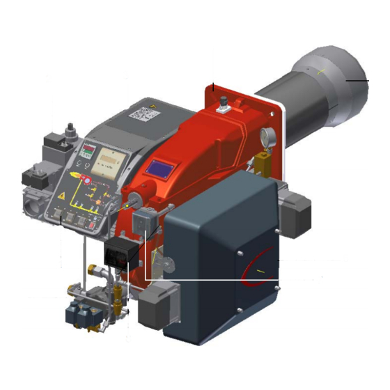
-2006/95/EC (Low Tension Directive) -2004/108/EC (Electromagnetic compatibility Directive) -2006/42/EC (Machinery Directive) Harmonized standards -UNI EN 676 (Automatic forced draught burners for gaseous fuels) -EN 55014-1 (Electromagnetic compatibility- Requirements for house hold appliances, electric tools and similar apparatus) -CEI EN 60335-1 (Specification for safety of household and similar elec- trical appliances) -EN 50165 (Electrical equipment of non-electric appliances for household and similar purposes. - Page 5 PART I: SPECIFICATIONS PART I: SPECIFICATIONS 1.0 BURNERS FEATURES Note: the figure is indicative only. Control panel with startup switch Gas valves group Electrical panel Flange Blast tube + Combustion head Silencer Air pressure switch Oil pressure switch Oil Pump Fig.
-
Page 6: Burner Type
PART I: SPECIFICATIONS 1.1 Burner model identification Burners are identified by burner type and model. Burner model identification is described as follows. Type HR75A Model MD. S. BURNER TYPE HR75A FUEL M - Natural gas L - LPG G - Light oil OPERATION (Available versions) PR - Progressive MD - Fully modulating... - Page 7 PART I: SPECIFICATIONS * NOTE ON THE WORKING SERVICE: the control box automatically stops after 24h of continuous working. The control box immediately starts up, automatically. 1.3 Country and usefulness gas categories COUNTRY CATEGORY ES GR SE NO CZ DK GB CY EE MT SK BG RO TR CH...
- Page 8 1.5 Overall dimensions (mm) O min O max Boiler recommended drilling template Burner flange AA AB AC AD AE Omin Omax HR75A 1.50 1253 69 550 435 28 305 374 750 352 618 361 254 270 235 300 453 M10 233 465 127 338 525 608 210 155 1.65 1253...
- Page 9 Fig. 2 - 3I2MG-21 v0 Hydraulic diagram oil inlet LEGEND POS OIL TRAIN oil outlet Filter Flexible hose Pump and pressure governor Electrical motor Solenoid valve Solenoid valve 16.1 Oil distributor Pressure gauge Pressure governor Pressure switch One-way valve combustion air 16.1 One-way valve Flexible hose Manual valve...
-
Page 10: Performance Curves
PART I: SPECIFICATIONS 1.6 How to read the burner “Performance curve” To check if the burner is suitable for the boiler to which it must be instal- Campo di lavoro bruciatori lled, the following parameters are needed: Tipo P60 Mod. M-xx.x.IT.A.0.50 - M-.xx.x.IT.A.0.65 furnace input, in kW or kcal/h (kW = kcal/h / 860);... - Page 11 PART I: SPECIFICATIONS 1.9 Pressure in the Network / gas flow rate curves(natural gas) HR75A M-.. Gas rate Stm Caution: the gas rate value is quoted on the x-axis, the related network pressure is quoted on the y-axis (pressure value in the combustion chamber is not included). To know the minimum pressure at the gas train inlet, necessary to get the requested gas rate, add the pressure value in the combustion chamber to the value read on the y-axis.
- Page 12 PART I: SPECIFICATIONS 1.11 Combustion head gas pressure curves depending on the flow rate The curves referred to the gas pressure in the combustion head, depending on the gas flow rate, are referred to the burner properly adjusted (percentage of residual O in the flues as shown in the “Recommended combustion values”...
- Page 13 PART I: SPECIFICATIONS 1.13 Pressure - rate in combustion head curves (natural gas) Curves are referred to pressure = 0 mbar in the combustion chamber! HR75A M-.. 1.14 Pressure - rate in combustion head curves (LPG) Curves are referred to pressure = 0mbar in the combustion chamber! HR75A L-..
- Page 14 PART II: INSTALLATION PART II: INSTALLATION 2.0 MOUNTING AND CONNECTING THE BURNER 2.1 Packing The burners are despatched in wooden crates whose dimensions are: 1672mm x 1072mm x 1016mm (L x P x H) Packing cases of this type are affected by humidity and are not suitable for stacking. The following are placed in each packing case: burner with gas train;...
- Page 15 PART II: INSTALLATION Keys Burner Fixing nut Washer Ceramic fibre plait Stud bolt Blast tube The burner is designed to work positioned according to the picture below. For different installations, please contact the Technical Department. SIDE UP SIDE DOWN...
- Page 16 PART II: INSTALLATION 2.4 Matching the burner to the boiler The burners described in this manual have been tested with combustion chambers that comply with EN676 regulation and whose dimensions are described in the diagram . In case the burner must be coupled with boilers with a combustion chamber smaller in dia- meter or shorter than those described in the diagram, please contact the supplier, to verify that a correct matching is possible, with respect of the application involved.
-
Page 17: Assembling The Gas Train
PART II: INSTALLATION 3.0 GAS TRAIN CONNECTIONS Referring to the P&ID of the burner, execute the connection. WARNING: BEFORE EXECUTING THE CONNECTIONS TO THE GAS PIPE NETWORK, BE SURE THAT THE MANUAL CUTOFF VALVES ARE CLOSED. 3.1 Assembling the gas train gas supply network ”direction”... -
Page 18: Mounting Positions
PART II: INSTALLATION MOUNTING POSITIONS Fig. 6 Fig. 7 Fig. 8 Fig. 9 3.3 Siemens VGD20.. and VGD40.. gas valves - with SKP2.. (pressure governor) Mounting When mounting the VGD.. double gas valve, two flanges are required (as for VGD20.. model, the flanges are threaded); to prevent cuttings from falling inside the valve, first fit the flanges to the piping and then clean the associated parts;... - Page 19 PART II: INSTALLATION Fig. 14 3.4 Pressure adjusting range The pressure adjusting range, downstream the gas valves group, changes according to the spring provided with the valve group. Siemens SKP actuator Keys 1 spring 2 cap Siemens VGD valves with SKP actuator: 0 - 22 15 - 120 100 - 250...
- Page 20 PART II: INSTALLATION 4.0 OIL TRAIN CONNECTIONS 4.1 Hydraulic diagrams for light oil supplying circuits Fig. 15 - Gravity circuit Fig. 16 - Ring circuit Fig. 17 - Suction circuit Manual valve Light oil filter Light oil feeding pump One way valve Flexible hoses Relief valve NOTE: in plants where gravity or ring feed systems are provided, install an automatic interception device.
- Page 21 PART II: INSTALLATION 4.2 Installation diagram of light oil pipes PLEASE READ CAREFULLY THE “WARNINGS” CHAPTER AT THE BEGINNING OF THIS MANUAL. From tank To tank Fig. 18 - Double-pipe system The burner is supplied with filter and flexible hoses, all the parts upstream the filter and downstream the return flexible hose, must be installed by the customer.
- Page 22 PART II: INSTALLATION Pipes should not contain air pockets. Rapid attachment joint should therefore be avoided and threaded or mechanical seal jun- ctions preferred. Junction threads, elbow joints and couplings should be sealed with removable sg component. The number of jun- ctions should be kept to a minimum as they are a possible source of leakage.
- Page 23 PART II: INSTALLATION on the pump. For further information, refer to the technical documentation of the pump. Suntec E.. Suntec TA HP Technik UHE-A...
-
Page 24: Electrical Connections
PART II: INSTALLATION 5.0 ELECTRICAL CONNECTIONS WARNING! Respect the basic safety rules. make sure of the connection to the earthing system. do not reverse the phase and neutral connections. fit a differential thermal magnet switch adequate for connection to the mains. - Page 25 PART III: OPERATION PART III: OPERATION WARNING: before starting the burner up, be sure that the manual cutoff valves are open and check that the pressure upstream the gas train complies the value quoted on paragraph “Technical specifications”. Be sure that the mains switch is closed.
- Page 26 PART III: OPERATION Fig. 19 - Burner front panel RWF50.X h min s Keys Lock-out LED Hi-flame operation LED Lo-flame operation LED “Ignition transformer operation” LED “Fan motor overload tripped” LED “EV2 opening” LED “EV1 opening” LED “Gas pressure switch signal ” LED Main switch (only on fully modulating burners) Operation selector MAN - AUTO (operation in manual or automatic mode): MIN = operation with minimum output...
-
Page 27: User Interface
PART III: OPERATION AIR FLOW AND FUEL ADJUSTMENT WARNING! During commissioning operations, do not let the burner operate with insufficient air flow (danger of formation of carbon monoxide); if this should happen, make the fuel decrease slowly until the normal combustion values are achieved. -
Page 28: Setting Menu
PART III: OPERATION Key F + A While pressing the two keys contemporarly, the code message will appear: by entering the proper password it is possible to access the Service mode. Info and Enter keys Used for Info and Service menues Used as Enter key in the setting modes Used as Reset key in the burner operation mode Used to enter a lower level menu... - Page 29 PART III: OPERATION User level (info): no password needed Service level (Service) Manifacturer level (OEM) PHASES LIST During operation, the following program phases are shown. The meaning for each phase is quoted in the table below Fase /Phase Funzione Function Ph00 Fase blocco Lockout phase...
-
Page 30: Info Level
PART III: OPERATION The burner and consequently the LMV2x.. are factory set; the air and fuel curves as set as well. Info level To enter the Info level, proceed as follows: in any menu position, press keys + and - at the same time, then the program will start again: the display will show OFF. until the display will show InFo, Press the enter (InFo) key then il will show the first code (167) flashing, on the right side it will show the data entered. - Page 31 PART III: OPERATION The Info level shows some basic parameters as: Parameter Description Cubic meters of fule (resettable) Operating hours (resettable) Device operating hours Burners start-ups (resettable) Total number of start-ups Burner number (i.e. serial number) Software version Software date Device serial number Customer code Version...
-
Page 32: Service Level
PART III: OPERATION If a message like the one below is shown during operation, it means that the burner is locked out and the Errore code is shown (in the example “error code:4”); this message is alternating with another message Diagnostic code (in the example “diagnostic code:3”). - Page 33 PART III: OPERATION Parameter Description Flame intensity % output, if set = automatic operation Actuators position, 00=combustibile; 01= aria Lock-outs number 701..725 Lock-outs History (see chapter 23 in the LMV2x manual) .the first parameter will be “954”: the percentage of flame is shown on the right. By pressinf + or - it is possible to scroll up/down the parameter list.
-
Page 34: Adjustments For Gas Operation
PART III: OPERATION 6.0 ADJUSTMENTS FOR GAS OPERATION 6.1 Air flow and gas adjustment startup the burner by selecting GAS by means of the switch on the burner control panel Adjust the air and gas flow rates, in according to the “air/gas ratio” curvepoints setting procedure on the LMV manual,. Check con- tinuosly, the flue gas analisys, to avoid combustion with air excess. - Page 35 PART III: OPERATION 6.4 Gas valves Siemens VGD - Version with SKP2. (provided with pressure stabilizer). To increase or decrease gas pressure, and therefore gas flow rate, remove the cap T and use a screwdriver to adjust the regulating screw VR. Turn clockwise to increase the flow rate, counterclockwise to reduce it.
- Page 36 PART III: OPERATION Remove the transparent plastic cap. Once air and fuel setting have been accomplished, startup the burner. During the pre-purge phase o the operation, turn slowly the adjusting ring nut VR in the clockwise direction (to increase the adju- sting pressure) until the burner lockout, then read the value on the pressure switch scale and set it to a value reduced by 15%.
- Page 37 PART III: OPERATION 6.11 (HR75A M-..) Center head holes gas flow regulation To adjust the gas flow, partially close the holes, as follows: loosen the three V screws that fix the adjusting plate D; insert a screwdriver on the adjusting plate notches and let it move CW/CCW as to open/close the holes; once the adjustmet is performed, fasten the V screws.
- Page 38 PART III: OPERATION 7.0 ADJUSTMENT PROCEDURE FOR LIGHT OIL OPERATION The light oil flow rate can be adjusted choosing a by-pass nozzle that suits the boiler/utilisation output and setting the delivery and return pressure values according to the ones quoted on the table below and the diagram on Fig. 23 (as far as reading the pressure values, see next paragraphs).
- Page 39 PART III: OPERATION Fig. 23 Example (Bergonzo): if a 220kg/h flow rate BERGONZO nozzle is provided, set the return pressure at 11bar, supply at 20bar on the delivery to get a 220kg/h flow rate. If the return pressure needed is 5bar, instead, act on the V adjusting screw on the pressure governor (see chapter on page 38).
- Page 40 PART III: OPERATION Fig. 24 Example (Bergonzo): if a 140kg/h flow rate BERGONZO 45° nozzle is provided, set the return pressure at 13bar, supply at 20bar on the delivery to get a 110kg/h flow rate. If the return pressure needed is 5bar, instead, act on the adjusting screw on the pressure gover- nor.
- Page 41 PART III: OPERATION Fig. 25...
- Page 42 PART III: OPERATION Oil Flow Rate Settings Once the air and gas flow rates are adjusted, turn the burner off, switch to the oil operation (OIL, on the burner control panel). with the electrical panel open, prime the oil pump acting directly on the related CP contactor (see next picture): check the pump motor rotation and keep pressing for some seconds until the oil circuit is charged;...
-
Page 43: Routine Maintenance
PART IV: MAINTENANCE PART IV: MAINTENANCE At least once a year carry out the maintenance operations listed below. In the case of seasonal servicing, it is recommended to carry out the maintenance at the end of each heating season; in the case of continuous operation the maintenance is carried out every 6 months. - Page 44 PART IV: MAINTENANCE 8.2 Removing the filter in the MULTIBLOC DUNGS MB-DLE 415 - 420 B01 1” 1/2 - 2” Check the filter at least once a year! Change the filter if the pressure difference between pressure connection 1 and 2 (Fig. 28-Fig. 29) Δp> 10 mbar. Change the filter if the pressure difference between pressure connection 1 and 2 (Fig.
- Page 45 PART IV: MAINTENANCE 8.3 Replacing the spring in the gas valve group To replace the spring in the gas valve group,proceed as follows: Carefully twist the protection cap 1 and the O-ring 2. remove the “set value” spring 3 from housing 4. Replace spring 3.
-
Page 46: Electrodes Adjustment
PART IV: MAINTENANCE 8.6 Electrodes Adjustment Important Note: Check the ignition and detection electrodes after removing/adjusting the combustion head. ATTENTION: avoid the ignition and detection electrodes to contact metallic parts (blast tube, head, etc.), other- wise the boiler’s operation would be compromised. Check the electrodes position after any intervention on the combustion head. -
Page 47: Seasonal Stop
PART IV: MAINTENANCE 8.9 Checking the detection current To check the detection signal follow the scheme in the picture below. If the signal is less than the value indicated, check the position of the detection electrode or detector, the electrical contacts and, if necessary, replace the electrode or the detector. Device Flame detector Minimum detection signal... -
Page 48: Wiring Diagrams
PART IV: MAINTENANCE 9.0 WIRING DIAGRAMS Refer to the attached wiring diagrams. WARNING 1 - Electrical supply 230V 50Hz 1 a.c./400V 50Hz 3N a.c. 2 - Do not reverse phase with neutral 3 - Ensure burner is properly earthed... -
Page 49: Troubleshooting
10.0 TROUBLESHOOTING TROUBLE CAUSE MAIN SWITCH OPEN LACK OF GAS MAXIMUM GAS PRESSURE SWITCH DEFECTIVE (IF PROVIDED) THERMOSTATS/PRESSURE SWITCHES DEFECTIVE FAN MOTOR THERMAL CUTOUT INTERVENTION OVERLOAD TRIPPED INTERVENTION AUXILIARY FUSES INTERRUPTED CONTROL BOX FAULTY DEFECTIVE ACTUATOR AIR PRESSURE SWITCH FAULT OR BAD SETTING MINIMUM GAS PRESSURE SWITCH DEFECTIVE OR GAS FILTER DIRTY IGNITION TRANSFORMER FAULT... - Page 52 C.I.B. UNIGAS S.p.A. Via L.Galvani, 9 - 35011 Campodarsego (PD) - ITALY Tel. +39 049 9200944 - Fax +39 049 9200945/9201269 web site: www.cibunigas.it - e-mail: cibunigas@cibunigas.it Note: specifications and data subject to change. Errors and omissions exceptd.
Need help?
Do you have a question about the HR75A Series and is the answer not in the manual?
Questions and answers