
Related Manuals for Unigas LO140 G-.TN Series


Summary of Contents for Unigas LO140 G-.TN Series
- Page 1 LO140 LO200 Light oil burners MANUAL OF INSTALLATION, USE AND MAINTENANCE BURNERS - BRUCIATORI - BRULERS - BRENNER - QUEMADORES - ГОРЕЛКИ M039154CE Rel. 4.2 01/2013...
- Page 2 WARNINGS THIS MANUAL IS SUPPLIED AS AN INTEGRAL AND ESSENTIAL PART OF THE PRODUCT AND MUST BE DELIVERED TO THE USER. INFORMATION INCLUDED IN THIS SECTION ARE DEDICATED BOTH TO THE USER AND TO PERSONNEL FOLLOWING PRODUCT INSTALLATION AND MAINTENANCE. THE USER WILL FIND FURTHER INFORMATION ABOUT OPERATING AND USE RESTRICTIONS, IN THE SECOND SECTION OF THIS MANUAL.
- Page 3 When the unit is out of use for some time the electric switch DIRECTIVES AND STANDARDS supplying all the power-driven components in the system (i.e. Gas burners pumps, burner, etc.) should be switched off. European directives: - Directive 2009/142/EC - Gas Appliances; - Directive 2006/95/EC on low voltage;...
-
Page 4: General Features
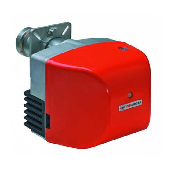
PART I: INSTALLATION GENERAL FEATURES This series is characterised by high performaces and width of the performance curves, when the pressure in the combustion chamber is high. They are also characterised for other important functional features: there are plugs which can be easily connected to the boiler and to the detecting probes, a pressure plug in the combustion chamber, all mechanical components are mounted on a plate which can be quickly taken off for maintenance. - Page 5 How to interpret the burner’s “Performance curve” To check if the burner is suitable for the boiler to which it must be installled, the following parameters are needed: furnace input, in kW or kcal/h (kW = kcal/h / 860); backpressure (data are available on the boiler’s ID plate or in the user’s manual). Example: Furnace input: kW 600 Backpressure: mbar 4...
-
Page 6: Burner Type
Burner model identification Burners are identified by burner type and model. Burner model identification is described as follows. Type LO140 Model G-. AB. (1) BURNER TYPE LO140 – LO200 G – Light oil (2) FUEL TN – Single-stage (3) OPERATION AB –... - Page 7 Overall dimensions(mm) Burner flange Boiler recommended drilling tempelate min. max. min. max. min. max. min. max. min. max. LO140 475 390 575 LO200 475 390 575 *AS/BS/CS: measures referred to burner with standard blast tube *AL/BL/CL: measures referred to burner with extended blast tube...
-
Page 8: Performance Range
Performance range LO140 G-.TN.. LO140 G-.AB.. LO200 G-.TN.. LO200 G-.AB.. To get the input in kcal/h, multiply value in kW by 860. Data are referred to standard conditions: atmospheric pressure at 1013mbar, ambient temperature at 15°C. NOTE: The performance curve is a diagram that represents the burner performance in the type approval phase or in the laboratory tests, but does not represent the regulation range of the machine. - Page 9 MOUNTINGS AND CONNECTIONS Packing The burners are dispatched in cardboard packages whose dimensions are: Standard blast tube: mm 600 x 370 x 400 (W x H x D) Extended blast tube: mm 750 x 370 x 400 (W x H x D) ...
- Page 10 Fig. 2 Once the burner is installed into the boiler, go on with the electrical and hydraulic connections, according to the diagrams shown on the following paragraphs. Matching the burner to the boiler The burners described in this manual have been tested with combustion chambers that comply with EN267 regulation and whose dimensions are described in the diagram .
- Page 11 Hydraulic diagrams for light oil supplying circuits - Gravity circuit - Ring circuit - Suction circuit Keys 1. Manual valve 2. Light oil filter 3. Light oil feeding pump 4. One way valve 5. Flexible hoses 6. Relief valve NOTE: in plants where gravity or ring feed systems are provided, install an automatic interception device (see n. 4– Fig.4).
- Page 12 Installation diagram of light oil pipes PLEASE READ CAREFULLY THE “WARNINGS” CHAPTER AT THE BEGINNING OF THIS MANUAL. Fig. 4 - Double-pipe system The burner is supplied with filter and flexible hoses, all the parts upstream the filter and downstream the return flexible hose, must be installed by the customer.
- Page 13 About the use of fuel pumps Make sure that the by-pass plug is not used in a single pipe installation, because the fuel unit will not function properly and damage to the pump and burner motor could result. Do not use fuel with additives to avoid the possible formation over time of compounds which may deposit between the gear teeth, thus obstructing them.
- Page 14 Suntec AT2 Viscosity 2 - 12 cSt Oil temperature 0 - 60 °C Min. inlet pressure - 0.45 bar to avoid gasing Max. inlet pressure 2 bar Max. return pressure 2 bar Rotation speed 3600 rpm max Keys 1 Low pressure regulation (first stage) 2 Pressure gauge port 3 Vacuum gauge port 4 Solenoid valve...
-
Page 15: Electrical Connections
Electrical connections Respect the basic safety rules. make sure of the connection to the earthing system. do not reverse the phase and neutral connections. fit a differential thermal magnet switch adequate for connection to the mains. ATTENTION: before executing the electrical connections, pay attention to turn the plant’s switch to OFF and be sure that the burner’s main switch is in 0 position (OFF) too. - Page 16 SETTING THE OIL FLOW RATE ATTENTION: before starting the burner up, be sure that the manual cutoff valves are open and check that the pressure upstream the gas train complies the value quoted on paragraph “Technical specifications”. Be sure that the mains switch is closed. ATTENTION: During commissioning operations, do not let the burner operate with insufficient air flow (danger of formation of carbon monoxide);...
- Page 17 Keys Light oil solenoid valve Pressure gauge Pump Fig. 6 Choice of the oil nozze – Single stage burners Nozzle 10 bar 12 bar 14 bar size(GPH) kg/h kcal/h kg/h kcal/h kg/h kcal/h 1.50 5.70 58.000 67.3 6.24 63.600 73.9 6.75 69.000 80.1...
- Page 18 Choice of the oil nozzle – Double stage burner Nozzle PUMP PRESSURE bar size(GPH) Flow rate kg/h 1.00 3.40 3.60 3.80 3.98 4.16 4.33 4.49 4.65 4.80 4.95 5.10 5.24 5.37 5.50 5.63 5.76 5.88 6.01 1.25 4.25 4.50 4.75 4.98 5.20 5.41 5.62 5.82 6.01 6.19 6.37 6.54 6.71 6.88 7.04 7.20 7.36 7.51 1.50 5.10 5.41 5.70 5.98 6.24 6.50 6.74 6.98 7.21 7.43 7.64 7.85 8.06 8.26 8.45 8.64 8.83 9.01 1.75...
-
Page 19: Combustion Head Adjustment
Double-stage burners Air damper position is set by means of the actuator cams both in low and high flame. As for the setting, refer to the next table. During the first setting, set the cam III between the cams I and II. Then, passing from the low to the high flame stage, or viceversa, change the setting according to the flame composition: if cam III is too near to the low flame position (cam II), flue gas can take place, because there is more fuel than air;... -
Page 20: Limitations Of Use
PART II - OPERATION LIMITATIONS OF USE THE BURNER IS AN APPLIANCE DESIGNED AND CONSTRUCTED TO OPERATE ONLY AFTER BEING CORRECTLY CONNECTED TO A HEAT GENERATOR (E.G. BOILER, HOT AIR GENERATOR, FURNACE, ETC.), ANY OTHER USE IS TO BE CONSIDERED IMPROPER AND THEREFORE DANGEROUS. THE USER MUST GUARANTEE THE CORRECT FITTING OF THE APPLIANCE, ENTRUSTING THE INSTALLATION OF IT TO QUALIFIED PERSONNEL AND HAVING THE FIRST COMMISSIONING OF IT CARRIED OUT BY A SERVICE CENTRE AUTHORISED BY THE COMPANY MANUFACTURING THE BURNER. -
Page 21: Routine Maintenance
PART III: MAINTENANCE At least once a year carry out the maintenance operations listed below. In the case of seasonal servicing, it is recommended to carry out the maintenance at the end of each heating season; in the case of continuous operation the maintenance is carried out every 6 months. - Page 22 After the disassembling the burner plate, the combustion head can be removed as follows: 5. unscrew the fixing screw VT 6. disconnect the ignition cable CA; unscrew the fixing nuts D and remove the combustion head from its housing; 7. adjust the electrodes; to replace them, if necessary, disconnect the cables and unscrew VE; 8.
-
Page 23: Seasonal Stop
Fig. 11 Cleaning and replacing the detection photoresistor To clean/replace the photoresistive detector, remove it from its slot. To clean the photoresistor, use a clean cloth, not cleaning sprays. Check the detection current To measure the detection current, refer to the diagram in Fig. 12. If the signal doesn’t suit the suggested value, verify the electric terminals, the cleaning of the combustion head and the position of the photoelectric cell and replace it if required. -
Page 24: Troubleshooting
TROUBLESHOOTING MAINS SWITCH OPEN FUSES INTERVENTION MAXIMUM PRESSURE SWITCH FAULT AUXILIARIES RELAY FUSES ... - Page 25 BURNERS EXPLODED VIEW SINGLE-STAGE BURNERS Position Description Position Description FLANGE (UP) 11.1 MOTOR PLATE FLANGE (HAUT) 11.2 FAN WHEEL BLAST TUBE 11.3 MOTOR COVER FIXING SCREW 11.4 PLATE FIXING SHAFT COVER 11.5 PHOTORESISTOR RUBBER COVER FOR UNLOCKING PUSHBUTTON 12.1 SWIRL VANE INDEX FIXING SCREW 12.2 IGNITION ELECTRODE...
- Page 27 DOUBLE-STAGE BURNERS Position Description Position Description BLAST TUBE 10.2 STUD ACTUATOR COVER FIXING SCREW 10.3 COVER 10.4 BUSH RUBBER COVER FOR UNLOCKING PUSHBUTTON OIL PIPE FLANGE 12.1 MOTOR PLATE FLANGE 12.2 FAN WHEEL FAIRLEAD 12.3 MOTOR CONTROL BOX 12.4 SHAFT HOUSING 12.5 PHOTORESISTOR...
- Page 29 SIEMENS OIL BURNERS AUTOMATIC CONTROLLER Colour code table SIEMENS LMO14 - LMO24 - LMO44 The LMO... burner controls are designed for the start-up and Status Colour code Colour supervision of single- or 2-stage forced draught oil burners in intermittent operation. Yellow-burning flames are supervised with Oil pre-heater heats, lllllllllll Yellow...
- Page 30 Connection diagram and internal diagram Remote lock-out reset button LMO14 FS Flame signal Flame signal amplifier K... Contacts of control relay 3-colour signal lamps M Burner motor OW Release contact of oil pre-heater t1 Pre-purge time t3 Pre-ignition time t3n Post-ignition time A´...
- Page 31 Measurement circuit for detector current µA DC microamperometer with internal resistance of 5 kW max. Blue Black Brown...
- Page 36 Note: Specifications and and data subject to change. Errors and omissions excepted.