Unigas HP60 Manual Of Installation - Use - Maintenance
Progressive and fully-modulating gas - light oil burners
Hide thumbs
Also See for HP60:
- Manual of installation - use - maintenance (96 pages) ,
- Manual (36 pages) ,
- Manual of installation - use - maintenance (88 pages)
Advertisement
Quick Links
See also:
Manual
HP60 - HP65
HP72 - HP73A
Progressive
and fully-modulating
gas - light oil burners
MANUAL OF INSTALLATION - USE - MAINTENANCE
BURNERS - BRUCIATORI - BRULERS - BRENNER - QUEMADORES - ГОРЕЛКИ
M03957CI Rel. 8.2 02/2010
Advertisement

Related Manuals for Unigas HP60


Summary of Contents for Unigas HP60
- Page 1 HP60 - HP65 HP72 - HP73A Progressive and fully-modulating gas - light oil burners MANUAL OF INSTALLATION - USE - MAINTENANCE BURNERS - BRUCIATORI - BRULERS - BRENNER - QUEMADORES - ГОРЕЛКИ M03957CI Rel. 8.2 02/2010...
- Page 2 WARNINGS THIS MANUAL IS SUPPLIED AS AN INTEGRAL AND ESSENTIAL PART OF THE PRODUCT AND MUST BE DELIVERED TO THE USER. INFORMATION INCLUDED IN THIS SECTION ARE DEDICATED BOTH TO THE USER AND TO PERSONNEL FOLLOWING PRO- DUCT INSTALLATION AND MAINTENANCE. THE USER WILL FIND FURTHER INFORMATION ABOUT OPERATING AND USE RESTRICTIONS, IN THE SECOND SECTION OF THIS MANUAL.
- Page 3 DIRECTIVES AND STANDARDS 3b) FIRING WITH GAS, LIGHT OIL OR OTHER FUELS Gas burners GENERAL European directives: The burner shall be installed by qualified personnel and in com- - Directive 90/396/CEE - Gas Appliances; pliance with regulations and provisions in force; wrong installation Directive 2006/95/EC on low voltage;...
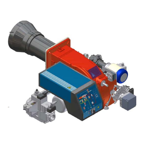
- Page 4 C.I.B. UNIGAS - M03957CI PART I: INSTALLATION GENERAL FEATURES This series represents monobloc gas burners made in die-cast aluminium housing, that can burn either gas or light oil, thanks to the adjustable combustion head which allows a good performance with both fuels. They can be provided in progressive or fully-modulating version.
- Page 5 C.I.B. UNIGAS - M03957CI Campo di lavoro bruciatori Tipo P60 Mod. M-xx.x.IT.A.0.50 - M-.xx.x.IT.A.0.65 Potenza kW Fig. 2 Data are referred to standard conditions: atmospheric pressure at 1013mbar, ambient temperature at 15°C Checking the proper gas train size To check the proper gas train size, it is necessary to know the available gas pressure value upstream the burner’s gas valve. Then subtract the backpressure.
- Page 6 C.I.B. UNIGAS - M03957CI Burner model identification Burners are identified by burner type and model. Burner model identification is described as follows. Type HP60 Model (1) BURNER TYPE HP60 (2) FUEL M - Natural gas G - Light oil (3) OPERATION (Available versions)
- Page 7 C.I.B. UNIGAS - M03957CI BURNER TYPE HP65...0.50 HP65...0.65 270 - 970 Output min. - max. kW Nat. gas - Light oil Fuel Gas category (see next paragraph) 29 - 103 Gas rate min. - max. kW (Stm min. - max. mbar...
- Page 8 C.I.B. UNIGAS - M03957CI BURNER TYPE HP72...1.50 HP72...1.65 HP72...1.80 330 - 1550 Output min. - max. kW Nat. gas - Light oil Fuel Gas category (see next paragraph) 35 - 164 Gas rate min. - max. (Stm min.- max. mbar...
- Page 9 Overall dimensions (mm) Boiler recommended drilling template...
-
Page 10: Table Of Contents
O - min O - max HP60 MG..0.40 1119 HP60 MG.. 0.50 1119 HP60 MG.. 0.65 1119 362 1115 685 HP65 MG.. 0.50 1156 139 382 1022 568 HP65 MG..1.50 1156 139 382 1148 694 HP65 MG..0.65 1156 139 382 1120 666 HP65 MG..1.65... -
Page 11: Hp60
C.I.B. UNIGAS - M03957CI Performance Curves HP60 MG.xx.x.xx.A.0.40 HP60 MG..50/65 HP65 MG..50/65 HP72 MG..0... 1000 1000 1200 1400 HP72 MG..1... HP73A ..1... 800 1000 1200 1400 1600 1800 1000 1500 2000 2500 To get the input in kcal/h, multiply value in kW by 860. - Page 12 C.I.B. UNIGAS - M03957CI Pressure in the network - gas rate curves HP60 HP65 Rp2(50) DN50 DN40 DN50 DN65 DN65 90 100 110 120 Gas rate Stm Gas rate Stm HP72...0.xx HP72...1.xx DN50 Rp 2" (50) DN65 DN65 DN80 DN80...
- Page 13 C.I.B. UNIGAS - M03957CI MOUNTINGS AND CONNECTIONS Packing Burners are despatched in cardboard packages and whose dimensions : 1280mm x 850mm x 760mm (L x P x H) Packing cases of this kind are affected by humidity and are not suitable for stacking. The following are placed in each packing case: burner with gas train detached;...
- Page 14 C.I.B. UNIGAS - M03957CI Gas train connections The next diagrams show the components of the gas train included in the delivery and which must be fitted by the installer.The diagrams are in compliance with the current laws. ATTENTION: BEFORE EXECUTING THE CONNECTIONS TO THE GAS PIPE NETWORK, BE SURE THAT THE MANUAL CUTOFF VALVES ARE CLOSED.
- Page 15 C.I.B. UNIGAS - M03957CI Assembling the gas grain gas supply network ”direction” arrows for installation Keys 1A..1E Gasket Gas filter Gas valves group Bellow joint Manual cock Fig. 5 - Example of gas train To mount the gas train, proceed as follows: 1-a) in case of threaded joints: use proper seals according to the gas used;...
- Page 16 C.I.B. UNIGAS - M03957CI MULTIBLOC DUNGS MBC300-700-1200SE (Threaded valves group) Mounting 1. Mount flange onto tube lines. Use appropriate sealing agent (see Fig. 10) 2. Insert MBC...SE. Note position of O rings (see Fig. 11). 3. Tighten screws A – H Fig.
- Page 17 C.I.B. UNIGAS - M03957CI WARNING: removing the four screws BS causes the device to be unserviceable! SIEMENS VGD..MOUNTING POSITIONS SKP1. SKP2. 7631z05/0101 Fig. 16 Fig. 14 Fig. 15 Fig. 13 Pressure adjusting range The pressure adjusting range, downstream the gas valves group, changes according to the spring provided with the valve group.
- Page 18 C.I.B. UNIGAS - M03957CI Hydraulic diagrams for light oil supplying circuits Fig. 17 - Gravity circuit Fig. 18 - Ring circuit Fig. 19 - Suction circuit Manual valve Light oil filter Light oil feeding pump One way valve Flexible hoses Relief valve NOTE: in plants where gravity or ring feed systems are provided, install an automatic interception device (see n.
- Page 19 C.I.B. UNIGAS - M03957CI Light oil piping installation diagram From tank To tank Fig. 20 (*) Only for installations with gravity, siphon or for- ced circulation feed systems. If the device installed Burner is a solenoid valve, a timer must be installed to Flexible hoses (fitted) delay the valve closing.
- Page 20 An external filter should always be installed in the suction line upstream of the fuel unit. Light oil pumps The pumps provided with these burners can be: HP60 - HP65: Suntec AJ6 HP72: Suntec E7 HP73A: Suntec TA2 Suntec AJ6...
- Page 21 C.I.B. UNIGAS - M03957CI Connecting the light oil flexible hoses To connect the flexible light oil hoses to the pump, proceed as follows, according to the pump provided: remove the closing nuts A and R on the inlet and return connections of the pump;...
- Page 22 C.I.B. UNIGAS - M03957CI Fig. 21: Power supply terminal board IG: main switch KM1: fan motor contactor KM2: pump motor contactor MP: pump motor MV: fan motor TP: pump motor thermal cutout TV: fan motor thermal cutout Fig. 22: Motors connectioni Rotation of fan motor and pump motor Once the electrical connection of the burner is executed, remember to check the rotation of the motor.
- Page 23 C.I.B. UNIGAS - M03957CI Electrical wiring diagram for burners provided with printed circuit (standard configuration). . As far as connections, refer to the terminal block showed on Fig. 23. Fig. 23: Terminal board for connections on printed circuit Connect the signal conductors from the boiler to the burner, as for the next elements ( Fig. 24 - Fig. 26) :...
- Page 24 C.I.B. UNIGAS - M03957CI Electrical wiring diagram for burners with no printed circuit board provided If the burner is ordered without printed circuit board, follow the next connections diagrams. Fig. 27 Progressive burners Fig. 29 Fully modulating burners Fig. 28 Probes connection (**) Probes connection (Fig.
- Page 25 C.I.B. UNIGAS - M03957CI ADJUSTMENTS Combustion head gas pressure curves depending on the flow rate Curves are referred to pressure = 0mbar in the combustion head! The curves referred to the gas pressure in the combustion head, depending on the gas flow rate, are referred to the burner properly adjusted (percentage of residual O in the flues as shown in the “Recommended combustion values”...
-
Page 26: Hp73A
C.I.B. UNIGAS - M03957CI HP72 HP73A 90 100 110 120 130 140 150 160 170 Gas rate Stm Gas rate Stm ATTENTION: before starting the burner up, be sure that the manual cutoff valves are open and check that the pres- sure upstream the gas train complies the value quoted on paragraph “Technical specifications”. - Page 27 C.I.B. UNIGAS - M03957CI Actuator The actuator provided can be either berger STM30../Siemens SQM40.. (see page 27) or Siemens SQL33.. (see page 30). IMPORTANT! the combustion air excess must be adjusted according to the in the following chart: Recommended combustion parameters...
- Page 28 C.I.B. UNIGAS - M03957CI Settings by means of Berger STM30../Siemens SQM40.. actuator Siemens SQM40 mensions Dimensions in SQM4... Berger STM30 Actuator cams High flame Stand-by and Ignition Low flame - gas Low flame - oil (SQM40..) Low flame - oil (STM30..)
- Page 29 C.I.B. UNIGAS - M03957CI shaft the air damper closes and the air flow rate decreases. Note: once the procedure is perfomed, be sure that the blocking nut RA is fasten. Do not change the position of the air damper rods.
- Page 30 C.I.B. UNIGAS - M03957CI Settings by means of the Siemens SQL33.. actuator set GAS fuel by means of the burner CM switch (it is placed on the burner control panel - see page 39) open the electrical panel to check the fam motor rotation and act directly on the related contactor (see next picture) Only for burners provided with Multibloc MB-DLE gas valves: before strting the burner up, set the slow opening.
- Page 31 C.I.B. UNIGAS - M03957CI 11 The burner is factory-set with the head in its MAX position (maximum output). To let the burner operate at a lower output, turn clockwise the VRT screw and move progressively the combustion head back towards the MIN position.
- Page 32 C.I.B. UNIGAS - M03957CI Calibration of air and gas pressure switches The air pressure switch locks the control box if the air pressure is not the one requested. If it happens, unlock the burner by means of the control box unlock pushbutton, placed on the burner control panel.
- Page 33 C.I.B. UNIGAS - M03957CI Adjustment procedure for light oil operation The light oil flow rate can be adjusted choosing a by-pass nozzle that suits the boiler/utilisation output and setting the delivery and return pressure values according to the ones quoted on the table below and the diagram on Fig. 36 (as far as reading the pressure values, see next paragraphs).
- Page 34 C.I.B. UNIGAS - M03957CI Fig. 36 Example (Bergonzo): if a 220kg/h flow rate BERGONZO nozzle is provided, set the return pressure at 11bar, supply at 20bar on the delivery to get a 220kg/h flow rate. If the return pressure needed is 5bar, instead, act on the V adjusting screw on the pressure...
- Page 35 C.I.B. UNIGAS - M03957CI Oil Flow Rate Settings by means of Berger STM30../Siemens SQM40.. actuator Once the air and gas flow rates are adjusted, turn the burner off, switch the CM switch to the heavy oil operation (OIL, on the bur- ner control panel (see page 39).
- Page 36 C.I.B. UNIGAS - M03957CI Fig. 37) as to get the nozzle pressure at 20bar (Monarch or Fluidics nozzles - see page 33-34). Pressure gauge port Fig. 38 Fig. 39 10 in order to get the maximum oil flow rate, adjust the pressure (reading its value on the PG pressure gauge) without changing the air flow rate set during the gas operation adjustments (see previous paragraph): checking always the combustion parameters, the adjustment is to be performed by means of the SV2 adjusting cam screw (see picture) when the cam has reached the high flame position.
- Page 37 C.I.B. UNIGAS - M03957CI The nozzle supply pressureis already factory-set and must not be changed. Only if necessary, adjust the supply pressure as follows (see related paragraph);insert a pressure gauge into the port shown on Fig. 40 and act on on the pump adjusting screw VR (see Fig.
- Page 38 C.I.B. UNIGAS - M03957CI Oil circuit The fuel is pushed into the pump 1 to the nozzle 3 at the delivery pressure set by the pressure governor. The solenoid valve 2 stops the fuel immission into the combustion chamber. The fuel flow rate that is not burnt goes back to the tank through the return circuit. The spill-back nozzle is feeded at constant pressure, while the return line pressure is adjusted by means of the pressure governor controlled by an actuator coupled to an adjusting cam.
- Page 39 C.I.B. UNIGAS - M03957CI PART II: OPERATION LIMITATIONS OF USE THE BURNER IS AN APPLIANCE DESIGNED AND CONSTRUCTED TO OPERATE ONLY AFTER BEING CORRECTLY CON- NECTED TO A HEAT GENERATOR (E.G. BOILER, HOT AIR GENERATOR, FURNACE, ETC.), ANY OTHER USE IS TO BE CONSI- DERED IMPROPER AND THEREFORE DANGEROUS.
- Page 40 C.I.B. UNIGAS - M03957CI NOTE: if the burner is fitted with Dungs VPS504, the pre-purgue phase starts once the gas proving system is successfully performed. Since the pre-purgue phase must be carried out with the maximum air rate, the control box drives the actuator opening and when the maximum opening position is achieved, the pre-purge time counting starts.
- Page 41 C.I.B. UNIGAS - M03957CI PART III: MAINTENANCE At least once a year carry out the maintenance operations listed below. In the case of seasonal servicing, it is recommended to carry out the maintenance at the end of each heating season; in the case of continuous operation the maintenance is carried out every 6 months.
- Page 42 C.I.B. UNIGAS - M03957CI Fig. 47 Fig. 46 Fig. 48 Inspection and replacement of the MULTIBLOC DUNGS MBC..SE filter (Threaded valves group) Inspect the filter at least once a year. Change the filter, if pressure value between pressure connections 1 and 2 is grea- ther than 10 mbar.
- Page 43 C.I.B. UNIGAS - M03957CI Replacing the spring in the gas valve group To replace the spring in the gas valve group,proceed as follows: Carefully twist the protection cap 1 and the O-ring 2. remove the “set value” spring 3 from housing 4.
-
Page 44: Hp73A
C.I.B. UNIGAS - M03957CI Adjusting the electrodes position Adjust the electrodes position, according to the quotes (in mm) shown on the next picture. HP60-65-72 Fig. 50 HP73A *8÷ Fig. 51 Cleaning/replacing the electrodes ATTENTION: avoid the electrodes to get in touch with metallic parts (blast tube, head, etc.), otherwise the boiler operation would be compromised. - Page 45 C.I.B. UNIGAS - M03957CI Cleaning and replacing the detection probe To clean/replace the detection photocell, proceed as follows: Disconnect the system from the electrical power supply. Shut off the fuel supply remove the photocell from its slot (see next picture);...
- Page 46 TROUBLESHOOTING TROUBLE CAUSE MAIN SWITCH OPEN LACK OF GAS MAXIMUM GAS PRESSURE SWITCH DEFECTIVE (IF PROVIDED) THERMOSTATS/PRESSURE SWITCHES DEFECTIVE FAN MOTOR THERMAL CUTOUT INTERVENTION OVERLOAD TRIPPED INTERVENTION AUXILIARY FUSES INTERRUPTED CONTROL BOX FAULTY DEFECTIVE ACTUATOR AIR PRESSURE SWITCH FAULT OR BAD SETTING MINIMUM GAS PRESSURE SWITCH DEFECTIVE OR GAS FILTER DIRTY IGNITION TRANSFORMER FAULT...
- Page 47 C.I.B. UNIGAS - M03957CI SPARE PARTS Desription Code HP60 HP65 HP72 HP73A 2020448 2020448 2020448 2020448 CONTROL BOX IGNITION ELECTRODES 20802B1 20802B1 2080280 2080278 2090018 2090018 2090018 2090018 OIL FILTER 2090119 2090119 2090119 2090119 GAS FILTER - Rp 2 2090117...
- Page 48 BURNER EXPLODED VIEW DESCRIPTION DESCRIPTION ITEM ITEM FRONT CONTROL PANEL PRESSURE PLUG LIGHT ELBOW LIGHT THROTTLE SHAFT LOCK-OUT RESET BUTTON BUTTERFLY GAS VALVE PROTECTION PHOTOCELL SWITCH STANDARD BLAST TUBE BOARD AIR PRESSURE SWITCH COVER SCREW IGNITION ELECTRODE NOZZLE LEVERAGE IGNITION CABLE NOZZLE HOLDER JOINT GAS MANIFOLD...
- Page 50 C.I.B. UNIGAS - M03957CI WIRING DIAGRAMS Burners not fitted with printed circuit board Complete key Light oil pump contactor coil Fan motor contactor coil Auxiliary contacts on light oil pump motor contactor Operation selector 0) Off - 1) Gas - 2) Light oil...
- Page 51 C.I.B. UNIGAS - M03957CI WIRING DIAGRAM Cod. 05-680 - Progressive burners...
- Page 52 C.I.B. UNIGAS - M03957CI WIRING DIAGRAM Cod. 05-681 - Fully modulating burners...
- Page 53 C.I.B. UNIGAS - M03957CI WIRING DIAGRAMS 21-0019 BURNERS FITTED WITH PRINTED CIRCUIT Complete key FUEL MANUAL SELECTOR: 0) STOP - 1) GAS - 2) LIGHT OIL MANUAL SWITCH 0)OFF 1)HIGH FLAME 2)LOW FLAME 3)AUTOMATIC FLAME DETECTION ELECTRODE GAS ELECTRO-VALVE UPSTREAM (OR VALVES GROUP)
- Page 57 APPENDIX SIEMENS LFL 1.3.. CONTROL BOX tion.The flame detector circuit F is activated (terminals 22 and 23 or 23/4) for the detector test and the paracitic light test. Automatic programme in the event of interruption and indication of posi- Where the burners do not have dampers (or have an independent 00 tion when interrupted damper control mechanism) there must be a bridge between terminals 6 By default, in the event of any kind of interruption, the flow of fuel is imme-...
- Page 58 ratus itself from recovery voltage through the strenght regulator circuit. Weight QRA2 60 g When the strenght regulator LR at terminal 20 gives the consent, the start-up programme for the apparatus comes to an end. Depending on QRA10 450 g. time variants, the programmer stops either immediately or at the end of a *Connect up in parallel to the measuring device a condenser 100µF, set time, without effecting the position of the contacts.
- Page 59 Programmer diagram duration of start-up pre-ventilation time 2nd safety time safety time interval before air pressure monitoring begins '1st safety time damper opening travel time pre-ignition time damper closure travel time 'pre-ignition time permissible post-combustion time interval for creating current between terminals 18 and 19 initial delay of damper OPEN response 'interval for creating current between terminals 17 and 19 interval before programmer automatically stops...
- Page 60 C.I.B. UNIGAS S.p.A. Via L.Galvani, 9 - 35011 Campodarsego (PD) - ITALY Tel. +39 049 9200944 - Fax +39 049 9200945/9201269 web site: www.cibunigas.it - e-mail: cibunigas@cibunigas.it Note: specifications and data subject to change. Errors and omissions exceptd.
Need help?
Do you have a question about the HP60 and is the answer not in the manual?
Questions and answers