Advertisement
Quick Links
5. INSTALLATION OF FIBER OPTIC MODULES
5.1
Installation of MPO cassettes
5.1 .1 12 fiber MPO cable
- Attach the white cable clips and position the cable tie.
- Install midi fan-out
- First clean MPO connector end face in the rear of the cassette, then insert the Quick-Fit
MPO cassette into the UCP panel. Next clean the MPO connector end face from the incoming
cable, dressing it into the cable clips at the rear of the panel (maintaining a minimum bend
radius of 50mm at all times). Finally, connect the incoming MPO cable to the MPO cassette.
5.1 .2 24 fiber MPO cable
- Attach the white cable clips, position the
cable tie and install the midi fan-out.
Note: Unused ports can be covered by blank Quick-Fit modules.
411-102033
- Same as 5.1.1
Rev.D
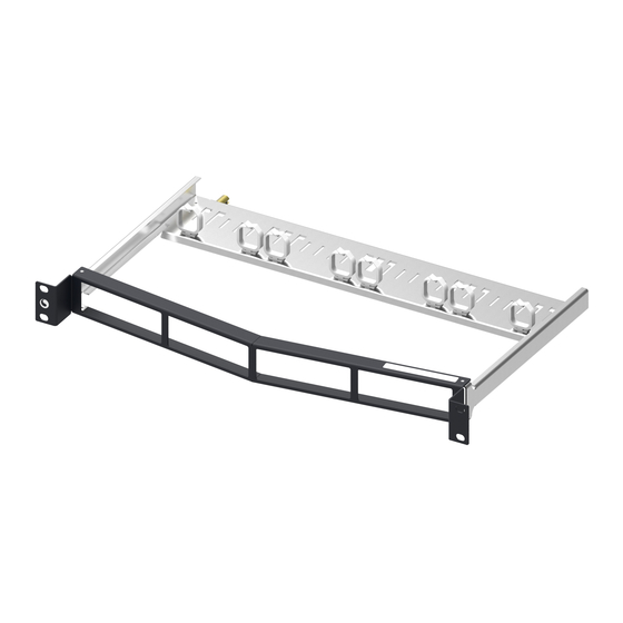
Instruction manual for Foldable UCP Patch Panel
1. SCOPE
The purpose of this specification is to provide specific instructions for assemble instruction
for retention packs.
1427544-1
Part number: 1427544-1 – Flat 1427592-1 – Angled
2. FOLDABLE UCP PATCH PANEL KITS CONTENTS
Description
Item
1
Panel with Arms
2
Rear Bracket
Grounding Nuts
3
4
M6 Screw /nut/gasket
5
Fiber Bracket
6
Hook and Loop Tie
3. ASSEMBLY REQUIREMENTS
3.1 Rotate the arm
3.3 Install the grounding bolt at the back of
the panel
To obtain information on CommScope
®
products,
©2023 CommScope, Inc.
contact your local CommScope
®
account
™
representative, PartnerPRO
Network Partner
or visit our website at
www.commscope.com
Instruction Manual
1.1 Purpose
1427592-1
Qyt
Unit
PCS
1
PCS
1
PCS
1
PCS
4
PCS
4
PCS
4
3.2 Fix the rear bracket with panel
3.4 Fix the panel in cabinet with screws
All Rights Reserved
411-102033
2023 May Rev D
Advertisement

Related Manuals for CommScope CPPR-QF-F-1U-E


Summary of Contents for CommScope CPPR-QF-F-1U-E
- Page 1 3.4 Fix the panel in cabinet with screws 3.3 Install the grounding bolt at the back of the panel Note: Unused ports can be covered by blank Quick-Fit modules. To obtain information on CommScope ® products, ©2023 CommScope, Inc. Rev.D contact your local CommScope ®...
- Page 2 411-102033 411-102033 2023 May Rev D 4. INSTALLATION OF COPPER MODULES 4.3 Installation of Sigma-Link Modules - Insert the Sigma-Link front cover 4.1 Installation of MRJ21 cassettes -Insert the MRJ21 & MRJ21 XG cassette -Connect the MRJ21 connector - Insert the Sigma-Link assembly into the opening of the Patch panel. Check TOP marking on the module and front cover.
Need help?
Do you have a question about the CPPR-QF-F-1U-E and is the answer not in the manual?
Questions and answers