Table of Contents
Advertisement
Quick Links
TC-96343-IP
Rev A, October 2022
commscope.com
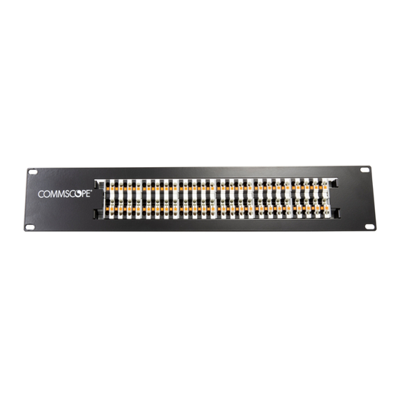
Constellation™ Power Transition Panel (CPT-PP-48C)
Content
1
INTRODUCTION . . . . . . . . . . . . . . . . . . . . . . . . . . . . . . . . . . . . . . . . . . . . . . . . . . . . . . . . . . . . . . . . . . . . . . . . . . . . . . . . . . . 2
1.1
Trademarks . . . . . . . . . . . . . . . . . . . . . . . . . . . . . . . . . . . . . . . . . . . . . . . . . . . . . . . . . . . . . . . . . . . . . . . . . . . . . . . . . . 2
1.2
Important Safety Cautions . . . . . . . . . . . . . . . . . . . . . . . . . . . . . . . . . . . . . . . . . . . . . . . . . . . . . . . . . . . . . . . . . . . . . 2
1.3
Constellation Products . . . . . . . . . . . . . . . . . . . . . . . . . . . . . . . . . . . . . . . . . . . . . . . . . . . . . . . . . . . . . . . . . . . . . . . . 3
1.4
Constellation Publications . . . . . . . . . . . . . . . . . . . . . . . . . . . . . . . . . . . . . . . . . . . . . . . . . . . . . . . . . . . . . . . . . . . . . 4
1.5
Contact Information . . . . . . . . . . . . . . . . . . . . . . . . . . . . . . . . . . . . . . . . . . . . . . . . . . . . . . . . . . . . . . . . . . . . . . . . . . . 4
2
PRODUCT DESCRIPTION . . . . . . . . . . . . . . . . . . . . . . . . . . . . . . . . . . . . . . . . . . . . . . . . . . . . . . . . . . . . . . . . . . . . . . . . . . . . 5
2.1
General Description . . . . . . . . . . . . . . . . . . . . . . . . . . . . . . . . . . . . . . . . . . . . . . . . . . . . . . . . . . . . . . . . . . . . . . . . . . . 5
2.2
Main Features . . . . . . . . . . . . . . . . . . . . . . . . . . . . . . . . . . . . . . . . . . . . . . . . . . . . . . . . . . . . . . . . . . . . . . . . . . . . . . . . 6
2.3
Specifications and Dimensions . . . . . . . . . . . . . . . . . . . . . . . . . . . . . . . . . . . . . . . . . . . . . . . . . . . . . . . . . . . . . . . . . 7
3
UNPACKING AND INSPECTION . . . . . . . . . . . . . . . . . . . . . . . . . . . . . . . . . . . . . . . . . . . . . . . . . . . . . . . . . . . . . . . . . . . . . . . 8
4
MOUNTING THE PANEL ON THE RACK. . . . . . . . . . . . . . . . . . . . . . . . . . . . . . . . . . . . . . . . . . . . . . . . . . . . . . . . . . . . . . . . . 9
5
CONNECTING THE POWER TRANSMITTER TO THE TRANSITION POINT PANEL . . . . . . . . . . . . . . . . . . . . . . . . . . . . . 10
6
INSTALLING THE POWER LEG OF THE HFPC CABLE . . . . . . . . . . . . . . . . . . . . . . . . . . . . . . . . . . . . . . . . . . . . . . . . . . . 12
Electronic Only Document (EOD)
Constellation Power Transition Panel
User
Manual
27924-A
Page
© 2022 CommScope, Inc.
Advertisement
Table of Contents

Related Manuals for CommScope Constellation CPT-PP-48C


Summary of Contents for CommScope Constellation CPT-PP-48C
-
Page 1: Table Of Contents
INSTALLING THE POWER LEG OF THE HFPC CABLE ........... 12 Electronic Only Document (EOD) © 2022 CommScope, Inc. -
Page 2: Introduction
19-inch rack, and terminating the 20 AWG and 16 AWG cables onto the panel. 1.1 Trademarks CommScope (logo), CommScope, and Constellation are trademarks of CommScope, Inc. Digital Electricity is a trademark of VoltServer, Inc. 1.2 Important Safety Cautions When installing or operating the panel, observe these safety cautions: •... -
Page 3: Constellation Products
760254291 C19 to 5-15P Cord CABLE-PWR C19-515P 760254292 Power Transition Panel CPT-PP-48C 760254293 Power Patch Cable CTX-CBL-10 760254294 Powered Backplane CPCB-1 760252855 Enclosure CPCE-1 760252854 HFPC Power Supply Bay Cover PM500-COVER 760254642 Page 3 © 2022 CommScope. All Rights Reserved. -
Page 4: Constellation Publications
TC-96343-IP 1.4 Constellation Publications Table 2 lists technical publications available for the Constellation system. These manuals can be accessed online using the QR code on the physical product or by contacting the CommScope Support Center at https://www.commscope.com/SupportCenter Table 2. Constellation Technical Publications... -
Page 5: Product Description
16 AWG copper conductors in the HFPC that ultimately terminate at powered backplane are fitted with wire ferrules prior to being inserted in the top slots of the terminal blocks. Page 5 © 2022 CommScope. All Rights Reserved. -
Page 6: Main Features
• Bottom Slot for Transmitter—the slot where a single conductor from the power transmitter interconnect lead attaches to a single terminal block on the panel. Page 6 © 2022 CommScope. All Rights Reserved. -
Page 7: Specifications And Dimensions
Figure 3. Power Transition Panel Dimensions Table 3. Power Transition Panel Specifications Parameter Value Height 3.47 in (8.83 cm) Width 19.0 in. (48.26 cm) Depth 1.75 in. (4.43 cm) Weight 1.93 lbs. (0.875 Kg) Page 7 © 2022 CommScope. All Rights Reserved. -
Page 8: Unpacking And Inspection
Inspect the exterior of the shipping carton for evidence of rough handling that may have damaged the components in the container. Open the carton and remove the panel while carefully checking the contents for damage. If damage is found or parts are missing, contact the CommScope Support Center using the URL: http://www.commscope.com/SupportCenter If damaged, save the carton for inspection by the carrier. -
Page 9: Mounting The Panel On The Rack
Align the four mounting holes with the four holes in the selected rack location. Secure the panel to the rack using the four screws provided. Refer to Figure 27928-A Figure 4. Mounting the Power Transition Panel Page 9 © 2022 CommScope. All Rights Reserved. -
Page 10: Connecting The Power Transmitter To The Transition Point Panel
Route the cable from the transition panel along the rack to the transmitter. Use a small screwdriver or equivalent to press on the clamp release on the terminal block (Figure 27930-A Figure 5. Releasing the Clamp Page 10 © 2022 CommScope. All Rights Reserved. - Page 11 Plug the transmitter end of the cable into the assigned location on the transmitter. Figure 7 shows the transmitter end of the cable plugged into the CTX-6. Figure 7. Transmitter End of Cable Plugged in Page 11 © 2022 CommScope. All Rights Reserved.
-
Page 12: Installing The Power Leg Of The Hfpc Cable
Once the conductors are terminated in ferrules, the appropriate conductors can be pushed into the appropriate holes in the panel. A properly terminated two-pair and four-pair HFPC cable that has been plugged into the CPT-PP-48C is shown in Figure Figure 8. Properly Terminated HFPC Page 12 © 2022 CommScope. All Rights Reserved.
Need help?
Do you have a question about the Constellation CPT-PP-48C and is the answer not in the manual?
Questions and answers