CommScope FPX Series Installation Instructions Manual
Fiber panel
Hide thumbs
Also See for FPX Series:
- User manual (28 pages) ,
- Installation instructions manual (34 pages)
Table of Contents
Advertisement
Quick Links
TECP-92-159, Rev D, May 2018
Content
INTRODUCTION . . . . . . . . . . . . . . . . . . . . . . . . . . . . . . . . . . . . . . . . . . . . . . . . . . . . . . . . . . . . . . . . . . . . . . . . . . . . . .2
Revision History . . . . . . . . . . . . . . . . . . . . . . . . . . . . . . . . . . . . . . . . . . . . . . . . . . . . . . . . . . . . . . . . . . . . . . . .2
Related Publications . . . . . . . . . . . . . . . . . . . . . . . . . . . . . . . . . . . . . . . . . . . . . . . . . . . . . . . . . . . . . . . . . . . . .2
Trademark Information . . . . . . . . . . . . . . . . . . . . . . . . . . . . . . . . . . . . . . . . . . . . . . . . . . . . . . . . . . . . . . . . . . . .2
Admonishments . . . . . . . . . . . . . . . . . . . . . . . . . . . . . . . . . . . . . . . . . . . . . . . . . . . . . . . . . . . . . . . . . . . . . . . . .3
1
DESCRIPTION . . . . . . . . . . . . . . . . . . . . . . . . . . . . . . . . . . . . . . . . . . . . . . . . . . . . . . . . . . . . . . . . . . . . . . . . . .3
2
BASIC INSTALLATION . . . . . . . . . . . . . . . . . . . . . . . . . . . . . . . . . . . . . . . . . . . . . . . . . . . . . . . . . . . . . . . . . . . . .5
2.1
2.2
300100108750 Rev D
This product is covered by one or more U.S.patents or their foreign equivalents.
www.cs-pat.com
For patents, see
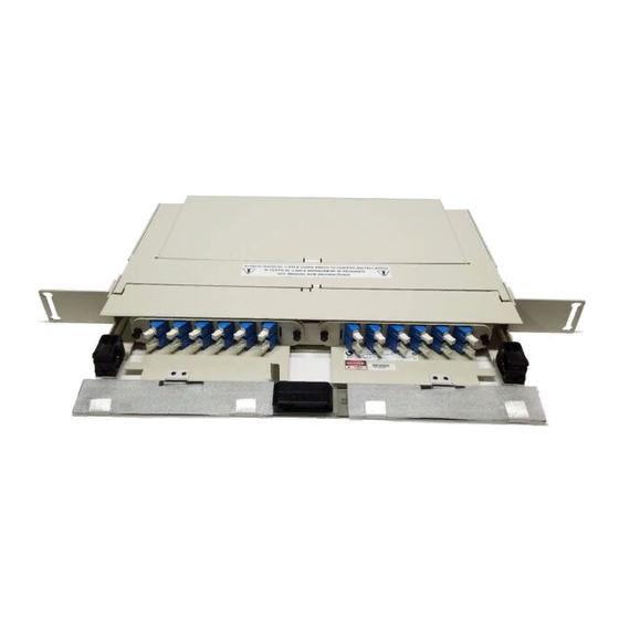
FPX Series
1RU & 2RU Series Fiber Panel
1RU PANEL
2RU PANEL
Mounting Bracket Options . . . . . . . . . . . . . . . . . . . . . . . . . . . . . . . . . . . . . . . . . . . . . . . . . . . . . . . . . . . .6
Installing the Panel on the Rack . . . . . . . . . . . . . . . . . . . . . . . . . . . . . . . . . . . . . . . . . . . . . . . . . . . . . . . .6
Installation Instructions
© 2018 CommScope.
25667-A
Page
(continued)
Page 1
All Rights Reserved.
Advertisement
Table of Contents

Subscribe to Our Youtube Channel
Related Manuals for CommScope FPX Series


Summary of Contents for CommScope FPX Series
-
Page 1: Table Of Contents
Installation Instructions TECP-92-159, Rev D, May 2018 FPX Series 1RU & 2RU Series Fiber Panel 1RU PANEL 25667-A 2RU PANEL Content Page INTRODUCTION ................2 Revision History . -
Page 2: Introduction
Additional corrections to splice tray cable routing instructions and diagrams. Related Publications Request at: http://www.commscope.com/SupportCenter Title/Description Publication Number FPX MPO Trunk Cable Clamp Kit Instructions ADCP-92-080 Trademark Information CommScope is a registered trademark of CommScope Inc. Page 2 © 2018 CommScope. All Rights Reserved. -
Page 3: Admonishments
(without splice trays) or for termination/splice. Figure 1 shows the 2RU panel. Caution: Adapter packs and MPO cassettes should not be both used in the same panel. 25677-A Figure 1. FPX 2RU Panel (Front View) Page 3 © 2018 CommScope. All Rights Reserved. - Page 4 LOCATION 25678-A SLIDING TRAY HINGED MOUNTING DOOR FRONT BRACKET (2) RADIUS LIMITERS LATCH DOOR FOR CABLE MANAGEMENT (8) DESIGNATION CABLE CLIP LABEL (2) (1 PER SIDE) Figure 3. FPX 1RU Termination/Splice Panel Page 4 © 2018 CommScope. All Rights Reserved.
-
Page 5: Basic Installation
Warning: Never install equipment in a wet location or during a lightning storm. When installing or modifying communication lines, disconnect lines at the network interface before working with uninsulated lines or terminals. Page 5 © 2018 CommScope. All Rights Reserved. -
Page 6: Mounting Bracket Options
2RU FIBER PANEL 25670-B Figure 5. Selecting a Mounting Bracket Option Installing the Panel on the Rack Using 12-24 screws, secure the panel on the rack as shown in Figure 6 Figure Page 6 © 2018 CommScope. All Rights Reserved. - Page 7 Figure 6. Installing 1RU Panel on Rack (23-Inch Rack Mount, 2-Inch Recess, Shown) 12-24 SCREWS AND WASHERS (4 PLACES) 25673-A Figure 7. Installing 2RU Panel on Rack (23-Inch Rack Mount, 2-Inch Recess, Shown) Page 7 © 2018 CommScope. All Rights Reserved.
-
Page 8: Installing Vertical Cable Guides (Vcgs)
Install the VCGs (one per side) as shown in Figure VCG (2) 1RU FIBER PANEL 6-32 SCREWS (2 PER VCG) (PROVIDED) VCG (2) 2RU FIBER PANEL 25674-A INSTALLATION HOLES FOR VCG Figure 8. Installing Vertical Cable Guides Page 8 © 2018 CommScope. All Rights Reserved. -
Page 9: Panel Grounding
VERTICALDIRECTION Figure 9. Grounding Location (Rear View of Panel) 2-HOLE LUG TERMINAL COPPER WIRE HOLE CENTER SPACING: 0.625 INCHES STRIP BACK INSULATION 24016-A PER LUG MANUFACTURER'S RECOMMENDATION Figure 10. 2-Hole Lug Terminal Page 9 © 2018 CommScope. All Rights Reserved. -
Page 10: Panel-Specific Installation Procedures
Adapter packs are installed in the same manner for both 1RU and 2RU panels. Adapter packs installed on left side of panel are angled left while adapter packs installed on right side are angled right. Install the adapter packs as shown in Figure 11 (2RU shown). Page 10 © 2018 CommScope. All Rights Reserved. -
Page 11: Installing Mpo Cassettes
MPO cassettes, the 2RU accommodates four. To install MPO cassettes, use the following procedure. 1. Temporarily remove the top cover so as to have access to the inside of the panel. Page 11 © 2018 CommScope. All Rights Reserved. - Page 12 LIMITER (13X) Figure 12. Radius Limiters to be Removed from 1RU Panel RADIUS LIMITER (4X) BRACKET (2X) 25838-A FRONT SIDE Figure 13. Radius Limiters and Brackets to be Removed from 2RU Panel Page 12 © 2018 CommScope. All Rights Reserved.
- Page 13 25682-A Figure 14. Installing MPO Cassettes To remove an MPO cassette, pull the Nylatch plunger fastener out, as shown in Figure 14, to release the cassette, then withdraw it from the panel. Page 13 © 2018 CommScope. All Rights Reserved.
-
Page 14: Installing A Cable Clamp
1. Determine the direction of cable entrance and install the cable clamp following the basic procedure provided in Section 3.6 on Page Note: Assure that the cable clamp is suitable for MPO cables. 2. Follow the routing shown in Figure Page 14 © 2018 CommScope. All Rights Reserved. - Page 15 ENOUGH TO COMPLETELY MPO CABLE PULL OUT THE SLIDING TRAY - DRAWER IN CLOSED POSITION 25684-A NOTE: - TOP COVER NOT SHOWN, FOR CLARITY - REAR COVER REMOVED Figure 16. Routing MPO Cable Page 15 © 2018 CommScope. All Rights Reserved.
-
Page 16: Preparing And Connecting A Pre-Connectorized Cable
‘L2’ +0.0 IN./-6.0 IN.(+0.0 CM/-15.2 CM) FANOUT LENGTH OSP/IFC ‘L3’ +0.0 IN./-6.0 IN. CABLE (+0.0 CM/-15.2 CM) 25717-A MULTIFIBER HEATSHRINK CLAMP SUBUNITS 6.0 IN. (15.2 CM) CONNECTORS Figure 17. IFC Stranded Cable Breakout Dimensions Page 16 © 2018 CommScope. All Rights Reserved. - Page 17 ‘L3’ +0.0 IN./-6.0 IN. (+0.0 CM/-15.2 CM) ‘L4’ +0.0 IN./-0.5 IN. (+0.0 CM/-1.27 CM) CLAMP INDIVIDUAL LENGTH FANOUT PROTECTIVE TUBING FLARE TUBE INDIVIDUAL CLAMP UPJACKETED FIBER 2571-A CONNECTORS Figure 19. OSP Cable Breakout Dimensions Page 17 © 2018 CommScope. All Rights Reserved.
- Page 18 Figure 20. Typical FPX Configured with Termination Only (Rear View) 5. Route the cable within the panel as shown in Figure 21 Figure CABLE LEFT SIDE ENTRY 25733-A Figure 21. Routing OSP Cable, Right Side Entry (Adapter Packs) Page 18 © 2018 CommScope. All Rights Reserved.
-
Page 19: Installing Pigtail Adapter Pack Assemblies And Splice Trays
Pigtails from the right side of the adapter bulkhead should be routed around to the left in a counterclockwise direction, pigtails from the left side of the adapter bulkhead should be routed around to the right in a clockwise direction. Page 19 © 2018 CommScope. All Rights Reserved. - Page 20 JACKETED FIBER (ROUTED 2X AROUND OUTER 900 MICRON FIBERS RADIUS LIMITERS) (ROUTED AROUND INNER RADIUS LIMITERS) INNER RADIUS LIMITER 26588-A Figure 23. Stranded Pigtail Routing, Routing from Right Side (When Viewed from Rear) Page 20 © 2018 CommScope. All Rights Reserved.
- Page 21 JACKETED FIBER (ROUTED 2X AROUND OUTER 900 MICRON FIBERS RADIUS LIMITERS) (ROUTED AROUND INNER RADIUS LIMITERS) INNER RADIUS LIMITER 26590-A Figure 24. Stranded Pigtail Routing, Routing from Left Side (When Viewed from Rear) Page 21 © 2018 CommScope. All Rights Reserved.
- Page 22 Figure 25. Mass Fusion Heat Shrink Splice Tray Cable Routing BARE FIBER LACING 26604-A JACKETED FIBER Figure 26. Splice Tray Cable Routing 4. Use A hook-and-loop strap to secure the splice tray to the panel. Page 22 © 2018 CommScope. All Rights Reserved.
-
Page 23: Installing Ifc/Osp Cable And Preparing For Splicing
Figure 27. OSP Cable Breakout Dimensions 4. Route the cable corresponding to Figure 28 Figure CABLE SPLICE TRAY ENTRY 25803-A FRONT SIDE Figure 28. Routing OSP Cable to Splice Tray, Left Side Entry Page 23 © 2018 CommScope. All Rights Reserved. - Page 24 OSP fibers within the splice tray as shown in Figure 30 for ribbon Figure 31 for stranded fiber JACKETED FIBER LACING BARE FIBER 26602-A PIGTAIL ALREADY INSTALLED Figure 30. Ribbon IFC/OSP Fiber Splice Tray Routing Page 24 © 2018 CommScope. All Rights Reserved.
-
Page 25: Performing A Ribbon Fiber Heat Fusion Splice
9. When done with all splice trays, wind the splice trays back into the panel so that they wind up stacked in the same order as at the beginning of this procedure. Page 25 © 2018 CommScope. All Rights Reserved. - Page 26 (35 IN. [88.9 CM)) FIBER LENGTH IN TRAY 26599-A Figure 33. Winding the Splice Chip Back Into Tray (Feeder Fiber on Top, Distribution Fiber on Bottom) Figure 34 shows a completed splice tray. Page 26 © 2018 CommScope. All Rights Reserved.
-
Page 27: Operation
Figure 35, and slide the drawer out to the retainer clip (one on each side). PRESS RED RELEASE 26675-A TO SLIDE OUT THE DRAWER Figure 35. Releasing and Sliding Out Drawer Page 27 © 2018 CommScope. All Rights Reserved. -
Page 28: Customer Information And Assistance
Figure 36. Releasing Open Drawer to Close It 5 CUSTOMER INFORMATION AND ASSISTANCE ® • To find out more about CommScope products, visit us on the web at www.commscope.com • For technical assistance, customer service, or to report any missing/damaged parts, visit us at http://www.commscope.com/SupportCenter...
Need help?
Do you have a question about the FPX Series and is the answer not in the manual?
Questions and answers