Compaq ProLiant 850R Setup And Installation Manual
Hide thumbs
Also See for ProLiant 850R:
- White paper (12 pages) ,
- Integration notes (32 pages) ,
- Manual (9 pages)

Related Manuals for Compaq ProLiant 850R


Summary of Contents for Compaq ProLiant 850R
- Page 1 ProLiant 850R Setup and Installation Guide First Edition (May 1997) 298824-001 Compaq Computer Corporation...
- Page 2 MERCHANTABILITY, FITNESS FOR PARTICULAR PURPOSE, GOOD TITLE AND AGAINST INFRINGEMENT. This publication contains information protected by copyright. No part of this publication may be photocopied or reproduced in any form without prior written consent from Compaq Computer Corporation. © 1997 Compaq Computer Corporation.
-
Page 3: Table Of Contents
Where to Go for Help ....................xiii Electronic Services ....................xiii Compaq CDs ......................xiv Other Hardcopy Documents..................xv Compaq Web Site....................xv Compaq Authorized Reseller or Service Provider ..........xv Customer Support ......................xvii Getting Product Updates....................xvii Chapter 1 Compaq ProLiant 850R Features Industry Support ...................... - Page 4 Inserting the Cage Nut in the Rack Frame ............2-12 Mounting the Support Rails ................2-13 Loading the Rack Server ..................2-14 Removing the ProLiant 850R Server from the Rack ..........2-15 Removing the Server Cover ..................2-15 Locating ProLiant 850R Server Internal Components........2-17 Installing the Server Cover..................
- Page 5 Installing a New Processor (CPU) in Socket 2 ........... 3-21 Installing the Processor Power Module in Socket 2........... 3-23 Installing a Processor Power Module In Socket 2 ..........3-24 Adding Memory to the ProLiant 850R............... 3-24 Maximum Memory Configuration ..............3-26 Installing DIMMs ....................3-26 Installing Mass Storage Devices ................
- Page 6 Installing an Operating System .................. 4-10 SMP Operating System Support ................. 4-11 Loading Compaq Device Drivers................4-11 Device Drivers from Compaq for Novell Products..........4-12 Windows NT Device Drivers from Compaq ............4-14 SCO OpenServer and SCO UnixWare Device Drivers from Compaq ....4-15...
- Page 7 Server Configuration and Utilities continued IBM OS/2 Device Drivers from Compaq ............4-16 Banyan VINES Device Drivers from Compaq ........... 4-17 Diagnostics and Other Utilities .................. 4-18 Chapter 5 Maintaining and Shipping the Server System Care and Maintenance ..................5-1 Routine Care of Server and Monitor ..............
- Page 8 Laser Safety Warnings ..................E-4 Compliance with CDRH Regulations ..............E-4 Compliance with International Regulations............E-4 Laser Product Label....................E-5 Laser Information ....................E-5 Battery Replacement Notice..................E-6 Battery Recycling Notice .....................E-6 Appendix F Specifications and Connector Interfaces ProLiant 850R Specifications..................F-1 Connector Interfaces..................... F-2 Index...
-
Page 9: Using The Setup And Installation Guide
Using the Setup and Installation Guide The Compaq ProLiant 850R Setup and Installation Guide is intended to help you set up your server for optimal performance. Use this guide along with the technical information on the hood labels, the Systems Reference Library CD, the SmartStart and Support Software CD, and the Management CD for complete and comprehensive reference source materials. - Page 10 Appendix C − − Power Cord Set Requirements This appendix contains requirements for the power cord set now available with the Compaq ProLiant 850R servers. A table lists power cord set requirements for each country. Appendix D − − Switches and Jumpers This appendix provides the correct settings for the switches on the System Board.
-
Page 11: Text Conventions
Text Conventions This document uses the following conventions to distinguish elements of text: Text Conventions Convention Keys Keys appear in boldface. A plus sign (+) between two keys indicates that they should be pressed simultaneously. USER INPUT User input appears in a different typeface and in uppercase. -
Page 12: Symbols On Equipment
xii Preface IMPORTANT: Text set off in this manner presents clarifying information or specific instructions. NOTE: Text set off in this manner presents commentary, sidelights, or interesting points of information. Symbols on Equipment WARNING: Any surface or area of the equipment marked with these symbols indicates the presence of a hot surface or hot component. -
Page 13: Where To Go For Help
Users can download drivers, patches, and Compaq service updates from the following sources: Online services, such as CompuServe, Prodigy, and America Online can be used if you are a member. Use the keywords below to access Compaq materials: CompuServe- The keywords are “GO COMPAQ”. -
Page 14: Compaq Cds
Security Management Server Maintenance and Service Guides (MSGs) Server reference guides Compaq SmartStart and Support Software CD Compaq SmartStart and Support Software CD is located in the Server Setup and Management pack and contains: System Configuration Utility software ROMPaq Drivers... -
Page 15: Other Hardcopy Documents
Compaq Management CD Compaq Management CD is located in the Server Setup and Management pack and contains: Insight Manager Utility software Online Help for the Insight Manager Utility Other Hardcopy Documents In addition to this guide, the following hardcopy documents are available:... - Page 16 Preface Compaq Worldwide Technical Support Telephone Numbers continued Location Voice Colombia 571-345-0266 571-312-0157 Czech Republic 42-2-232-8772 42-2-232-8773 Denmark 45-90-4545 45-90-4595 Equador 593-2504540 Europe/Middle East/Africa (49) 089-9933-2891 Finland 9800-206-720 90-6155-9899 (358-800-1-206720) (358-0-61559899 France (33 1) 41-33-4455 (33 1) 41-33-4263 Germany...
-
Page 17: Customer Support
Compaq servers for advanced networks. Download TechNotes from the Systems Reference Library CD. Getting Product Updates The latest product updates are available on the Internet at the Compaq World Wide Web site. Access the site through the following address: http://www.compaq.com... -
Page 18: Compaq Proliant 850R Features
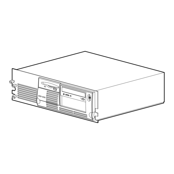
Chapter 1 Compaq ProLiant 850R Features Compaq ProLiant 850R architecture combines the power of the Intel Pentium Pro processor with PCI bus architecture to provide optimum performance. The innovative architecture gives you maximum performance and flexibility. Figure 1-1. Compaq ProLiant 850R server... -
Page 19: Drive Positions
Compaq ProLiant 850R Features Drive Positions The ProLiant 850R server can house up to five mass storage devices. The following illustration and table describe the recommended drive configurations. Figure 1-2. ProLiant 850R server drive positions Table 1-1 Description of Drive Bays... -
Page 20: Processors And Processor Power Modules
Processors and Processor Power Modules 200/66 256-KB cache Intel Pentium Pro Processor Dual Intel Pentium Pro Processor capability Processor Power Module (DC-to-DC converter) Figure 1-3. Processor Power Module on ProLiant 850R System Board Table 1-2 Processor/Processor Power Module Locations Location... -
Page 21: Cache Memory And System Architecture
Board Slot (Slot 4) Side B Figure 1-4. Locating ProLiant 850R expansion slots Two PCI slots for access to PCI bus providing peripheral transactions at a PCI clock speed of 33 MHz. One Shared PCI/ISA slot for access to either the PCI bus or to the ISA bus. -
Page 22: Feature Board
Feature Board The drawing below illustrates Feature Board connectors. Video Header for Replacement Battery Connector Internal Wide-Ultra External SCSI Connector Internal vs. External Fast-Wide Battery Jumper SCSI-2 Connector Figure 1-5. Video, SCSI, and battery replacement connectors for the Feature Board The highlights of the Feature Board include the following: Video Integrated PCI Video Controller provides maximum resolution of... -
Page 23: Integrated Network Controller
Power Switch Cover Security Feature Warranty Three-Year On-Site Limited Worldwide Warranty Server Management and Configuration Compaq offers an extensive set of features and optional tools to support effective server management and configuration. These features are described in this guide: SmartStart Fault Tolerance... -
Page 24: Smartstart
RAID 1 - mirroring RAID 4 - data guarding RAID 5 - distributed data guarding Fault tolerance for the ProLiant 850R server is covered in the online documentation on the System Reference Library CD. Compaq Insight Manager Compaq Insight Manger is an easy-to-use intuitive software utility for collecting server information. -
Page 25: Automatic Server Recovery-2 (Asr-2)
Automatic Server Recovery-2 (ASR-2) A feature that can enable the server to boot automatically from the operating system or the Compaq Utilities. If there is a critical system failure, Automatic Server Recovery-2 allows you to restart the server and page a designated system administrator. -
Page 26: Security Features
When Insight Manager alerts you that a component may be eligible for Pre-Failure Warranty replacement, follow the on-screen instructions or contact a Compaq Authorized Service Provider in your area. A yellow status indicator on the Insight Manager control panel signals that a component is in a degraded condition and recommends that you replace the component in a prefailure condition. -
Page 27: Server Installation Overview
Chapter 2 Server Installation Overview This section covers the following information about your new ProLiant 850R server: Installing the Server into the rack, including: How to attach the mounting hardware to the rack How to place the server into the rack and attach cables How to access the internal components of the rack-mounted server. - Page 28 Rack Planning and Installation Guide (for more information order the Guide (PN 165719-004) from a Compaq reseller) This guide provides you with complete details on Compaq racks and rack-mountable products.
-
Page 29: Rack Warnings And Precautions
Rack Warnings and Precautions WARNING: Always load the heaviest item first and always load the rack from the bottom up. This makes the rack “bottom-heavy” and helps prevent the rack from becoming unstable. WARNING: To reduce the risk of personal injury, fire, or damage to the equipment, do not overload the AC supply branch circuit that provides power to the rack. - Page 30 WARNING: To reduce the risk of personal injury or damage to the server you must support the server when either loading or unloading it from the rack. The ProLiant 850R server is not attached to the support rails of the rack and may fall if not supported when extended from the rack.
-
Page 31: Server Warnings And Precautions
CAUTION: The Rack-Mountable Compaq ProLiant 850R server must always be operated with the system unit cover on. Proper cooling will not... -
Page 32: General Steps For Installing The Server
Installation Guide to reduce the risk of physical injury and/or damage to your server. Ordering SmartStart Activation Keys. If you are purchasing an operating system from Compaq (optional), you should order the SmartStart Activation Keys. For ordering information, refer to the Server Setup and Management pack shipped with your server. -
Page 33: Selecting A Site And Unpacking The Server
SmartStart CD initialization procedures, refer to the server Setup and Management pack shipped with your server. Installing Compaq Insight Manager. Use this utility to manage your server. For Compaq Management CD initialization procedures refer to the server Setup and Management pack shipped with your server. -
Page 34: Installing Hardware Options And Setting Switches
Server Installation Overview CAUTION: Protect the server from power fluctuations and temporary interruptions with a regulating uninterruptible power supply (UPS). This device protects the hardware from damage caused by power surges and voltage spikes and keeps the system in operation during a power failure. Installing Hardware Options and Setting Switches General tasks that are performed regularly are included at the end of this... -
Page 35: Locating Materials
Locating Materials All of the parts needed for ProLiant 850R rack installation is included. Figure 2-2. Rack mounting hardware included with the server Locate the following materials shipped with your new server: Rack mounting hardware One pair of support rails Eight M6 x 1.0-12L Phillips screws... -
Page 36: Preparing Support Rails
Optional uninterruptible power supply (UPS) Optional monitor, keyboard, etc. SmartStart Activation Keys. If purchasing application software, such as SmartStart from Compaq you will need to order the activation keys. Preparing Support Rails Each pair of support rails supports one rack-mountable server. -
Page 37: Measuring With The Template
2-11 Measuring with the Template The template provided with the server offers an easy and reliable way to properly position the server in the rack. Use the tabs on the template to suspend it from the lower hole of a two-hole set of perforations in the vertical side rails. Use a pencil to mark the attachment points for the support rails, the cage nut for the front bezel thumb screw, and the top of the server. -
Page 38: Inserting The Cage Nut In The Rack Frame
2-12 Server Installation Overview Figure 2-4. Measuring with the template 3. After marking the front of the rack, flip the template over and mark the back rails of the rack. Open the rear door of the rack to access the back rails. -
Page 39: Mounting The Support Rails
2-13 Insert the tip of the fitting tool through the other side of the perforation and hook the opposite lip of the cage nut. Figure 2-5. Inserting cage nut Using the fitting tool as a lever, pry the cage nut into position. Mounting the Support Rails WARNING: To reduce the risk of personal injury or damage to the equipment, be sure that the rack leveling feet are extended to the floor... -
Page 40: Loading The Rack Server
WARNING: To reduce the risk of personal injury or damage to the server you must support the server when either loading or unloading it from the rack. The ProLiant 850R server is not attached to the support rails of the rack and may fall if not supported when extended from the rack. -
Page 41: Removing The Proliant 850R Server From The Rack
Be sure the thumb screw is fully engaged before closing the rack door. Removing the ProLiant 850R Server from the Rack Reverse the steps from the “Loading the Rack Server” section procedure to remove the server from the rack. - Page 42 WARNING: To reduce the risk of personal injury or damage to the server you must support the server when either loading or unloading it from the rack. The ProLiant 850R server is not attached to the Support Rails of the rack and may fall if not supported when extended from the rack.
-
Page 43: Locating Proliant 850R Server Internal Components
2-17 Locating ProLiant 850R Server Internal Components The following illustration provides an inside view of the main features of the server. The table which follows is keyed to illustrate key features. Figure 2-9. An inside view of the Pentium Pro-based server... -
Page 44: Installing The Server Cover
2-18 Server Installation Overview Pentium Pro Board Interior Components continued Processor Power Module 2 Socket Intel Pentium Pro Processor (CPU) 2 ZIF Socket Intel Pentium Pro Processor (CPU) 1 Memory module sockets (DIMM) Installing the Server Cover Reverse the steps from the “Removing the Server Cover” procedure to replace the server cover. -
Page 45: Securing The System Using A Padlock
2-19 Securing the System Using a Padlock If desired, the server cover can be locked (with a customer-supplied padlock) to prevent unauthorized access to system components. To install the cable lock provision, complete the following steps: Remove one of the thumb screws from the rear of the computer. Position the bottom part of the cable lock provision over the screw hole and replace the thumb screw with a Torx screw. -
Page 46: Removing The Front Bezel
2-20 Server Installation Overview Removing the Front Bezel Remove the front bezel to gain access to drive bays and removable media bays. WARNING: Before removing the front bezel, ensure that the computer is turned off and that the power cord is disconnected from the electrical outlet. -
Page 47: Installing The Front Bezel
Pull the bezel to the left to unseat the bezel from the hinge . Figure 2-13. Removing the front bezel Installing the Front Bezel Follow the steps listed below to install the front bezel on the ProLiant 850R server. WARNING:... - Page 48 2-22 Server Installation Overview To install the front bezel: Push the right side of the bezel into the slot on the server at about 30 degrees to seat the hinge of the bezel into the chassis . Push the left side of the bezel into the chassis . Figure 2-14.
-
Page 49: Using The Power Switch Cover Security Feature
2-23 Using the Power Switch Cover Security Feature The server is shipped from the factory with the power switch cover security feature in the locked position. This protects the server from accidentally being shutdown due to incidental contact with the power switch cover. To turn the server ON or OFF, you must use a thin object to depress the center circle of the power switch cover. - Page 50 2-24 Server Installation Overview ins58.eps Figure 2-16. Removing the power switch from the front bezel Rotate the switch cover assembly 180 degrees . Insert the switch into the front bezel as shown below . Make sure that you include the spring, the clips on the switch engage, and the center post of the switch cover aligns with the hole in the bezel.
-
Page 51: Opening The Cd-Rom Manually
2-25 Opening the CD-ROM Manually The CD-ROM supplied with your server operates like a standard CD-ROM, refer to the online documentation for further details. If the CD-ROM will not open automatically you can open it by using the emergency eject button. CAUTION: Before beginning this procedure, turn off the power to your server. -
Page 52: Installing Hardware Options
Chapter 3 Installing Hardware Options Before installing or replacing an option in your server, follow these preliminary steps: Back up your server data. Power down the server and remove the power cable. Remove the server from the rack and place on a secure table or work bench. -
Page 53: Identifying Expansion Slots
(Slot 4) Side B Figure 3-1. Locating ProLiant 850R expansion slots Replacing an Expansion Board To replace an expansion board on the ProLiant 850R server first remove the existing board and then install the new board. Refer to the procedures below. -
Page 54: Removing An Expansion Board
Removing an Expansion Board This procedure also applies to removal of the Feature Board (which resides on side B of the Riser Board). Remove the server from the rack, and remove the server cover. Refer to Chapter 2, “Server Installation Overview” for detailed procedures. Expansion board removal should progress from the top of the Riser Board down. - Page 55 Installing Hardware Options If the expansion board is on side B of the Riser Board, remove the screw and retaining bracket . Remove the Feature Board to access the slot below it . Note: Power Supply not drawn for clarity. Figure 3-3.
-
Page 56: Installing An Expansion Board
Installing an Expansion Board To install a PCI or ISA expansion board on side A of the Riser Board, follow the steps listed below. Remove the Server from the rack and remove the server cover. Refer to Chapter 2, “Server Installation Overview,” for details. Locate the correct vacant slot. - Page 57 Installing Hardware Options Side A Figure 3-6. Installing a board into an expansion slot Replace the retaining screw. Replace the server cover. To reconfigure the server refer to Chapter 4. “Server Configuration Utilities.” To install an expansion board on side B of the Riser Board, follow the steps listed below.
- Page 58 Remove the retaining screw and the retainer bracket . Remove the Feature Board to access the slot below it . Then remove the expansion slot cover . Note: Power Supply not drawn for clarity. Figure 3-7. Removing the retaining screw, bracket, Feature Board, and slot cover Slide the expansion board into the expansion slot and press it firmly into place.
- Page 59 Installing Hardware Options IMPORTANT: When you install a board, make sure you press firmly on the board so that the whole connector seats properly in the Riser Board slot. Replace the Feature Board. Replace the retaining bracket, and retaining screws. Note: Power Supply not drawn for clarity.
-
Page 60: Replacing The Riser Board And Riser Board Brace
CAUTION: If the Riser Board or Riser Board Brace needs to be replaced, both must be sent to Compaq as one unit. If they are sent separately, all warranties are voided for those components. Removing the Riser Board and... -
Page 61: Installing The Riser Board And Riser Board Brace
Replace all expansion boards and the Feature Board. Replace the Server cover. Place the ProLiant 850R server into the rack. Reconnect all cabling and reconfigure the server. Refer to Chapter 4, “Server Configuration and Utilities.” Installing the Riser Board and... -
Page 62: Replacing A Processor
3-11 When installing this assembly refer to the drawing below for proper alignment. Figure 3-11. Installing the Riser Board and Riser Board Brace Replacing a Processor To replace a processor on the System Board, refer to the label inside the server cover, or follow the instructions below. - Page 63 3-12 Installing Hardware Options Remove the Feature Board and the expansion board below it, (if one is installed). If you have an external battery connected to the Feature Board disconnect it. CAUTION: Disconnecting the Feature Board’s external battery looses stored configuration data. You must reconfigure your system when you reconnect the battery.
- Page 64 3-13 Remove the heat sink retaining clip by pressing down on the clip’s extended tab until it releases from the safety catch and lift the clip out of the way . Figure 3-13. Removing the heat sink clip Lift the heat sink and thermal pad off the processor. The thermal pad may be stuck to the heat sink or processor.
- Page 65 3-14 Installing Hardware Options Release the original processor from the socket by pulling the handle on the ZIF socket out and upward. Figure 3-15. Releasing the ZIF socket and removing the processor Lift the processor out of the socket . CAUTION: The handle on the ZIF socket in your server may not be identical to the handle shown in the drawing.
-
Page 66: Installing A New Processor (Cpu) In Socket 1
3-15 If you do not have a Processor Power Module to install, follow the “Installing a New Processor (CPU)” procedure below to complete the processor installation process. Installing a New Processor (CPU) in Socket 1 Confirm that the existing processor has been removed from socket 1. Refer to the “Replacing a Processor”... - Page 67 3-16 Installing Hardware Options CAUTION: The thermal pad must be installed or damage will occur to your processor. Thermal Pad Figure 3-17. Installing the processor thermal pad and heat sink Install the heat sink. Install the heat sink retaining clip by attaching the end opposite from the extended tab, then pressing down on the extension tab until the clip snaps into place.
-
Page 68: Replacing A Processor Power Module
3-17 Figure 3-18. Installing the heat sink retaining clip Replace the disk drive cage, the expansion board, Feature Board, and assemble the server and return it to the rack by reversing steps 1 through 4 of this procedure. Use the System Configuration Utility to reconfigure your system. Refer to Chapter 4, “System Configuration and Utilities.”... -
Page 69: Removing A Processor Power Module From Socket 1
3-18 Installing Hardware Options Removing a Processor Power Module From Socket 1 Remove the server from the rack and remove the server cover. Refer to Chapter 2, “Server Installation Overview,” for details. Remove the front bezel. WARNING: To reduce the risk of personal injury from hot surfaces, allow the internal system components to cool before touching. - Page 70 3-19 Use your thumbs to brace slightly on the module, while at the same time pushing the latches outward with your index fingers until the latches snaps open. As the socket latches spread open, the module comes out of the socket. Remove the module from the socket on the System Board, as shown below.
-
Page 71: Installing A Processor In Socket 2
3-20 Installing Hardware Options Insert the module straight into a socket on the System Board. Installing a Processor Power Module Figure 3-21. As the module goes into the socket, the socket latches spread open. Use your thumbs to press firmly on the module, while at the same time pushing the latches inward with your index fingers until the latches snap into place. -
Page 72: Installing A New Processor (Cpu) In Socket 2
3-21 Installing a New Processor (CPU) in Socket 2 Confirm the location of Pentium Pro ZIF Socket 2 on the System Board. Open the ZIF Socket by pulling the handle slightly out and then up. Align the new processor with the ZIF socket. IMPORTANT: The processor is keyed to ensure correct alignment. - Page 73 3-22 Installing Hardware Options Install the thermal pad to line up with the rectangular pad on top of the processor. CAUTION: The thermal pad must be installed or damage will occur to your processor. Thermal Pad Figure 3-23. Installing the processor thermal pad and heat sink Install the heat sink.
-
Page 74: Installing The Processor Power Module In Socket 2
3-23 Install the heat sink retaining clip by attaching the end opposite from the extended tab, then pressing down on the extension tab until the clip snaps in place . Installing the heat sink retaining clip Figure 3-24. Installing the Processor Power Module in Socket 2 Every Intel Pentium Pro Processor comes with a Processor Power Module (DC-to-DC converter) that provides power stability for the processor and the... -
Page 75: Installing A Processor Power Module In Socket 2
Refer to Chapter 4, “System Configuration and Utilities.” Adding Memory to the ProLiant 850R The ProLiant 850R memory system uses Error Checking and Correcting (ECC) memory to detect and correct all single-bit memory errors and detect other uncorrectable memory errors. Refer to the System Reference Library CD, specifically the section on memory upgrades for more information. - Page 76 Then install a fourth DIMM in DIMM socket 4 (System Board connector J9). Any combination of DIMMs may be used in the ProLiant 850R server as long as at least 32 MB of memory is installed; for example, one 32-MB module, one 16-MB module, one 64-MB module, and one 128-MB module may be used simultaneously.
-
Page 77: Maximum Memory Configuration
3-26 Installing Hardware Options Maximum Memory Configuration The ProLiant 850R server allows ultimate expansion to 512 MB. In the maximum memory configuration, all four DIMM sockets would be populated with 128-MB DIMMs. Installing DIMMs CAUTION: Electrostatic discharge can damage electronic components. - Page 78 3-27 Dual Inline Memory Module (DIMM) DIMM key slot DIMM Expansion Board Socket Figure 3-27. Aligning DIMM in the memory expansion slots Insert each DIMM straight down into a socket on the System Board. As the DIMM goes into the socket, the latches close. Use your thumbs to press firmly down on the DIMM while pushing the latches inward with your index fingers until the latches snap into place.
-
Page 79: Installing Mass Storage Devices
SCSI hard drives attached to the SCSI controller must be either internal or in an external storage system, but not both. CAUTION: The ProLiant 850R server does not support the installation of IDE or EIDE fixed disk drives. Figure 3-29. - Page 80 1” height hard drive 1” height Drive Installation Guidelines When adding SCSI hard drives to your ProLiant 850R server, observe the following guidelines: A maximum of seven SCSI devices per controller may be added. Each SCSI drive must have a unique address.
- Page 81 3-30 Installing Hardware Options SCSI ID Settings for Compaq Hard Drives The following chart provides the SCSI ID jumper settings for Compaq SCSI hard drives. Table 3-2 SCSI ID Settings SCSI ID Bit 2 Bit 1 Bit 0 Installing Mass Storage Devices Hard drives may be installed into drive bays 2 and 3, but these positions are more often used for devices requiring user access.
- Page 82 3-31 Sercure the drive with one additional retaining screw installed through the side of the drive cage. Attach the power and data cables to the drive. Installing a Hard Drive in Bay 0 NOTE: Bay 0 accepts a 1-inch height hard drive. Remove the server cover.
-
Page 83: Installing External Storage Devices
3-32 Installing Hardware Options Installing External Storage Devices Optional mass storage devices can be connected to the Compaq ProLiant 850R by using the optional external Fast-Wide SCSI-2 port on the back of the unit. Installing a 3.5-Inch Drive into a 5.25-Inch Drive Bay To install a 3.5-inch drive into a 5.25-inch drive bay, complete the following:... - Page 84 3-33 Install the guide screws, provided behind the front bezel on the chassis, into the front screw holes on the left and right side of the bracket. Figure 3-31. Installing the guide screw in the drive bracket Install the bracket and drive into the drive bay. Secure the bracket with one screw through the right side of the drive cage.
-
Page 85: Connecting The Power Cord And Peripheral Devices
3-34 Installing Hardware Options Connect the drive power and signal cables. Figure 3-33. Connecting the drive cables 10. Remove the blank drive bezel from the inside of the front bezel, if necessary, or leave it when adding a hard drive. 11. - Page 86 3-35 WARNING: Any RJ-45 receptacle marked with these symbols indicates a Network Interface Connection. To reduce risk of electrical shock, fire, or damage to the equipment, do not plug telephone or telecommunications connectors into this receptacle. WARNING: To reduce the risk of electrical shock or damage to your equipment, do not disable the power cord grounding feature.
-
Page 87: Rear Panel Connectors
Figure 3-34. Location of rear panel connectors and switches Cables at the rear of the rack should be gathered and tie-wrapped together. Then secure the cable assembly to the nearest ProLiant 850R Support Bracket. Table 3-3 Rear Panel Connectors Connector... -
Page 88: Scsi Cabling Guidelines
Connects a monitor with a PCI graphics controller. SCSI Cabling Guidelines Only controllers listed in the tables below are supported by the ProLiant 850R. Refer to these tables to determine the parts that you need for successful cabling solutions for the ProLiant 850R. -
Page 89: Internal Scsi Cabling
One I/O bracket with screws (PN 199830-001). The I/O Bracket and provided screws must be used when installing a Smart /2P or Smart 2SL Array Controller in slot 2 of the ProLiant 850R server. Replace the existing bracket with the I/O Bracket using two of the screw locks provided. - Page 90 3-39 Continued Model 1 Includes IDE Wide-Ultra and Fast- Fast SCSI-2 Non Hot-Plug 2/8 Dat Drive, 4/16 cable for IDE CD-ROM, a Wide SCSI Non Hard Drives TurboDat Drive, SCSI cable, and a 68 to Hot-Plug Hard Drives SCSI CD-ROM 50 pin adapter.
-
Page 91: External Cabling For Primary Storage
3-40 Installing Hardware Options External Cabling For Primary Storage Table 3-5 External Cabling for Primary Storage ProLiant 850R Servers Hot-Plug Wide-Ultra Hard Hot-Plug Fast SCSI-2 Drives, Fast-Wide SCSI Hard Drives Hard Drives Rack mount ProLiant storage systems No additional cables required. -
Page 92: External Cabling For Secondary Storage
3-41 External Cabling for Secondary Storage Table 3-6 External Cabling for Secondary Storage ProLiant 850R Servers 2/8 Dat Drive, External 4/16 TurboDat 15/30 DLT Drive 4/16 TurboDat Drive, Autoloader PN DLT Tape Array Internal 4/16 TurboDat 142187-001 Model 0 and Model 4... -
Page 93: Server Configuration And Utilities
Assisting in running diagnostic tools such as Test and Inspect Utilities If the SmartStart and Support Software CD is used the first time the server is configured, the SmartStart program automatically creates a system partition and installs the System Configuration Utility and other Compaq utilities in that partition. IMPORTANT: This Compaq system utilities partition should not be confused with the partition(s) created by your operating system. -
Page 94: Resolving Resource Conflicts
The .CFG files provide information such as switch settings, IRQs, and software installation guidelines. The .CFG files for Compaq computers are located on the System Configuration diskettes and SmartStart and Support Software CD (SmartStart CD). -
Page 95: Starting The System Configuration Utility
The Compaq ProLiant 850R server employs a system architecture with an expansion slot that must share system resources with one of the embedded system devices. A PCI expansion board in slot 3 must share an interrupt with the embedded PCI Network Interface card. -
Page 96: System Configuration Utility Main Menu
IMPORTANT: The Compaq System Configuration Utility must be run after adding Plug and Play ISA boards to ensure the boards are correctly configured. Operating System Installation - Allows you to install one of the operating systems listed or to specify installation of an operating system that is not listed. - Page 97 Play board which is set to “Legacy” mode, then you must use “Step 2: Add or Remove Boards” to add the board to the system configuration. The Compaq ProLiant 850R server employs a system architecture with an expansion slot that must share system resources with one of the embedded system devices.
-
Page 98: System Partition
Server Configuration and Utilities IMPORTANT: If you edit a function or resource in “Step 3: View or Edit Details,” be sure also to review Step 4: Examine Required Switches.” Step 4: Examine Required Switches This step displays the required switch and jumper settings for most ISA boards. Find the appropriate board’s switch and jumper settings and adjust them to match the settings displayed on the screen. -
Page 99: Creating A New System Partition
If you used SmartStart to configure your server, the new System Partition is created automatically. If SmartStart was not used for server configuration follow the procedure below to create one now: Insert the Compaq SmartStart CD in the CD-ROM drive and turn on the server. IMPORTANT: The system partition requires about 32 MB of disk space at the beginning of the hard drive and an unused entry in the boot record. -
Page 100: Upgrading The System Partition
Upgrading the System Partition To upgrade the system partition, follow this procedure: Insert the Compaq SmartStart CD in the CD-ROM drive and turn on the computer. Select Upgrade System Partition. Select to upgrade the utilities. SmartStart copies the new utilities from the CD to the system partition. -
Page 101: Configuring Pci Boards Automatically
The .SCI files can be used to restore a previous configuration using the System Configuration menu and Restore System Configuration from a .SCI File submenu. The .CHL files are text-based files displaying information that is stored in the corresponding .SCI file. Table 4-1 System Configuration History Log Files Filename... -
Page 102: Removing Boards
CD or diskette. Not all operating systems ship with each server. Consult your local reseller or Compaq Customer Service if you need a SmartStart pack with additional operating system support. Some operating systems have driver support/updates but not an integrated SmartStart installation. -
Page 103: Smp Operating System Support
IBM OS/2 Warp Server with SMP 4.0 Loading Compaq Device Drivers Drivers are located on the Support Software Diskette and on the Compaq SmartStart and Support Software CD. The drivers on the Support Software Diskette may be newer versions with new functionality and upgraded utilities. -
Page 104: Device Drivers From Compaq For Novell Products
Novell Products Your server must have certain device drivers to operate with the Novell operating systems. These drivers are located on the Compaq SmartStart and Support Software CD shipped with the server. If you use SmartStart to install the operating system, these drivers will be installed automatically. Otherwise, you can use SmartStart to create a Support Software for Novell Products (NSSD) diskettes to support a manual installation of Novell’s operating... - Page 105 Please read NETWORK.RDM from the NSSD diskettes for further information. Your ProLiant 850R server comes with one IDE channel to which you can attach IDE devices. For each IDE channel to which you have an attached device, you must load the following drivers found on the NSSD diskette according to the type of device attached: For each IDE channel: LOAD A:\IDE\IDEATA.HAM...
-
Page 106: Windows Nt Device Drivers From Compaq
Windows NT retail product. These drivers are also located on the Compaq SmartStart CD. The drivers on the SSD may be newer versions with new functionality, problem fixes, and so on. If you use SmartStart to install your operating system, these drivers are installed automatically. -
Page 107: Sco Openserver And Sco Unixware Device Drivers From Compaq
Before attempting to install the SCO UNIX software, boot this diskette and read the README file for the Compaq EFS. It will instruct you on how to use the boot time loadable driver diskettes along with the SCO installation media. -
Page 108: Server Configuration And Utilities
IBM OS/2 Warp Server 4.0, IBM OS/2 Warp Server Advanced 4.0, IBM OS/2 SMP version 2.11, IBM OS/2 Warp Server with SMP 4.0, IBM OS/2 Warp 3.x, and IBM OS/2 2.x. These drivers are located on the Compaq SmartStart CD you received with your server. If you use SmartStart to install your operating system, these drivers are loaded automatically. -
Page 109: Banyan Vines Device Drivers From Compaq
Banyan VINES operating system. Compaq provides driver support for Banyan VINES 6.00 and above, including the new VINES 7.00. These drivers are located on the Compaq SmartStart CD you received with your server. You can use SmartStart to create a Banyan VINES Support Software Diskette (SSD) from Compaq to support a manual installation of Banyan VINES. -
Page 110: Diagnostics And Other Utilities
Power-On Self-Test (POST). Run the Inspect Utility after the computer has been configured to get information about the operating system environment. For instructions on using the Diagnostics Utility and other Compaq utilities, refer to the online section on Diagnostics Tools. -
Page 111: Maintaining And Shipping The Server
Chapter 5 Maintaining and Shipping the Server This chapter provides information on general cleaning and maintenance steps required to keep your server working properly. It also gives suggestions on repackaging and shipping the server and components. System Care and Maintenance Important care and maintenance issues for your server include: Performing routine care Preparing your server for shipment... -
Page 112: Preparations For Shipping
Maintaining and Shipping the Server Never cover the ventilation slots on the monitor. To lessen interference in a two-monitor system, place the monitors as far apart as possible. WARNING: To reduce the risk of personal injury or damage to the equipment, for the next two suggestions, turn off your server and unplug the AC power cord from the power receptacle. - Page 113 Disconnect the AC power cord from the AC outlet, then from the server. Disconnect the system components and external devices from their power sources, then from the server. CAUTION: Ensure that all boards are seated properly in the expansion slots before shipping the server. To protect the server components and external devices, pack them in their original packing boxes or similar packaging with sufficient packing material.
-
Page 114: Appendix A Electrostatic Discharge
Use a portable field service kit with a folding static-dissipating work mat. If you do not have any of the suggested equipment for proper grounding, have an Authorized Compaq Reseller install the part. For more information on static electricity or assistance with product installation, contact your Authorized... -
Page 115: Installing A New Battery
When your server no longer automatically displays the correct date and time, you may need to replace the battery that provides power to the real-time clock. Under normal use, battery life is usually about five to ten years. Use Compaq replacement battery 160274-001 a 600-milliampere alkaline, 4.5-volt battery. -
Page 116: Installing The System Board Battery
The lithium battery may explode if mistreated. The battery is soldered in place and may not be removed. Do not abuse or disassemble. Use only replacement batteries supplied by Compaq Computer Corporation (spare part number 160274-001). To install the new battery, complete the following steps: 1. - Page 117 Remove the backing from the adhesive on the hook-and-loop fastener strip. Place the battery and the hook-and-loop fastener strip on the designated chip, as shown in the following illustration. Plug the battery connector onto pins 1-4 of header E2 on the System Board.
-
Page 118: Feature Board Battery Replacement
Memory Invalid,” it may mean that you need to replace the battery providing power to the nonvolatile CMOS on the Feature Board. Battery life is usually about five to ten years under normal use. Use Compaq replacement battery 160274-001 or a comparable 600-milliampere alkaline, 4.5-volt battery. - Page 119 Remove the server from the rack and place on a sturdy table or work bench and remove the server cover. Refer to Chapter 2 for detailed instructions. Battery Placement for Feature Board Remove all boards installed on side B of the Riser Board (that is the Feature Board and possibly a PCI expansion board).
- Page 120 (earthed) power outlet that is easily accessible to the operator. The grounding type plug is an important safety feature. Turn on the server. 10. Run the Compaq System Configuration Utility to reconfigure the system. Refer to Chapter 4, "System Configuration and Utilities."...
-
Page 121: Power Cord Set Requirements
Power cord sets for use in other countries must meet the requirements of the country where you use the server. For more information on power cord set requirements, contact your Authorized Compaq Dealer. General Requirements The requirements listed below are applicable to all countries: The length of the power cord must be at least 6.0 feet (1.8 m) and a... -
Page 122: Country-Specific Requirements
C-2 Power Cord Set Requirements Country-Specific Requirements Use the following table to identify the appropriate accredited agency in your country. Table C-1 Power Cord Set Requirements - By Country Country Accredited Agency Applicable Note Numbers Australia EANSW Austria Belgium CEBC Canada Denmark DEMKO... - Page 123 Power cord sets for use in other countries must meet the requirements of the country where you use the server. For more information on power cord set requirements, contact your Authorized Compaq Dealer. General Requirements The requirements listed below are applicable to all countries: The length of the power cord must be at least 6.0 feet (1.8 m) and a...
- Page 124 C-2 Power Cord Set Requirements Country-Specific Requirements Use the following table to identify the appropriate accredited agency in your country. Table C-1 Power Cord Set Requirements - By Country Country Accredited Agency Applicable Note Numbers Australia EANSW Austria Belgium CEBC Canada Denmark DEMKO...
-
Page 125: Switches And Jumpers
Setting System Board Switches The Compaq ProLiant 850R System Board has two switch banks (SW1 and SW2) located on the System Board that are used to set the overall configuration of your server. Switch SW1 is an 8-position switch (S1-S8) that provides configuration settings of your computer. -
Page 126: System Maintenance Switch Sw1 Settings
D-2 Switches and Jumpers System Maintenance Switch SW1 Settings The following table defines the function for each switch setting on SW1. Table D-1 System Maintenance Switch Settings on SW1 Position Status Switch Function 1-Password Enabled Power-on Password Defeat: On position permanently clears Disabled all system passwords. -
Page 127: Scsi Device Jumper Settings
NIC Operating Mode The ProLiant 850R server comes standard with the Compaq Integrated 10/100 TX UTP Controller. The controller automatically differentiates between the 10Mb and 100Mb environments when the RJ-45 connector is used. The controller is limited to 10Mb operation when the BNC connector is used. - Page 128 D-4 Switches and Jumpers System Board Battery Jumper Settings The System Board allows you to add an external battery, if the battery embedded on the System Board fails. A Jumper on header E2 on the System Board allows you to choose the internal battery and an external battery. Placing the jumper on pins 6-7 selects the internal battery.
-
Page 129: Regulatory Compliance Notices
Modifications The FCC requires the user to be notified that any changes or modifications made to this device that are not expressly approved by Compaq Computer Corporation may void the user's authority to operate the equipment. Cables Connections to this device must be made with shielded cables with metallic RFI/EMI connector hoods in order to maintain compliance with FCC Rules and Regulations. -
Page 130: Declaration Of Conformity For Products Marked With The Fcc Logo-United States Only
(1) this device may not cause harmful interference, and (2) this device must accept any interference received, including interference that may cause undesired operation. For questions regarding this declaration, contact: Compaq Computer Corporation P. O. Box 692000, Mail Stop 510101 Houston, Texas 77269-2000 Or, call (281) 514-3333 To identify this product, refer to the Series number found on the product. -
Page 131: European Union Notice
European Union Notice Products with the CE Marking comply with both the EMC Directive (89/336/EEC) and the Low Voltage Directive (73/23/EEC) issued by the Commission of the European Community. Compliance with these directives implies conformity to the following European Norms: EN55022 (CISPR 22) - Electromagnetic Interference EN50082-1 (IEC801-2, IEC801-3, IEC801-4) - Electromagnetic Immunity... -
Page 132: Laser Devices
E-4 Regulatory Compliance Notices Laser Devices The CD-ROM drive contains a laser device. All Compaq systems equipped with laser device comply with appropriate safety standards including International Electrotechnical Commision (IEC) 825. With specific regard to the laser, the equipment complies with laser product performance standards set by government agencies as a Class 1 laser product. -
Page 133: Laser Product Label
Laser Product Label The following label or equivalent is located on the surface of your CD-ROM drive. This label indicates that the product is classified as a CLASS 1 LASER PRODUCT. This label appears on a laser device installed in your product. Laser Information Laser Type Semiconductor GaAIAs... -
Page 134: Battery Replacement Notice
Real-Time Clock circuit. There is a danger of explosion and risk of personal injury if the battery is incorrectly replaced or mistreated. Replacement is to be done by an Authorized Compaq Service Provider using the Compaq spare designated for this product. For more information about Real-Time Clock battery replacement or proper disposal, contact your Compaq Authorized Reseller or your Compaq Authorized Service Provider. -
Page 135: Specifications And Connector Interfaces
Appendix F Specifications and Connector Interfaces This appendix provides operating and performance specifications for the Compaq ProLiant 850R components. For other specifications, refer to the Systems Reference Library CD. ProLiant 850R Specifications Table F-1 ProLiant 850R Dimensions Height 5.1 in 12.85 cm... -
Page 136: Connector Interfaces
F-2 Specifications and Connector Interfaces Table F-1 ProLiant 850R continued Temperature Range ° ° ° ° Operating Range to 95 to 35 ° ° ° ° Non-operating Range to 122 to 50 Relative Humidity (noncondensing) Operating 8% to 90% 8% to 90%... - Page 137 Chapter summaries ix OS/2 4-16 Compaq Windows NT 4-14 Internet address xvii NetWare 4-12 TechNotes 1-1, 1-9 OS/2 4-16 Compaq Insight Manager 1-7 Windows NT 4-14 Compaq Web Site xv Diagnostics System Configuration Utility 4-18 ProLiant 850R Setup and Installation Guide...
- Page 138 I-2 Index DIMMs 1-4 Front bezel adding memory 3-24 installing 2-21 removing 4-10 removing 2-20 slot identification 3-25, 1-6 Disk drive cage removing 3-12, 3-18 Grounding methods A-1 DRAM installed 1-4 Drive bay description 3-29 positions 1-2 Hard drives, Pre-Failure Drivers, loading software 4-11 Warranty 1-9 Drives, installation guidelines 3-29...
- Page 139 SMP 4-11 Logs, Server Health 1-6 Option configuration files See .CFG files Options, installing 3-1 OS/2, device drivers 4-16 Maintaining the server 5-1 Manual, organization ix Partitioning using System Partition Utility 4-6 PCF Files 4-2 ProLiant 850R Setup and Installation Guide...
- Page 140 I-4 Index Rack (continued) removing boards 4-10 video about installing rack model slots 1-4 server 2-2 PCI configuration files RAID levels 1-7 See .PCF files RAM 1-4 Rear panel connectors 3-36 Pentium Pro Regulatory notices E-1 Pre-Failure Warranty 1-9 processor 1-3 Removable media storage 3-29 Phone support xiii Removing...
- Page 141 Feature Board 1-5 Summary of Installation Guide Insight Manager Alert 1-9 contents ix integrated network Symbols xi, xii controller 1-6 integrated 256-KB secondary cache 1-4 power module 1-3 Pre-Failure Warranty 1-9 processor board 1-3 ProLiant 850R Setup and Installation Guide...
- Page 142 I-6 Index System Board board jumper settings D-4 Warranty Configuration Utility 4-1 Details of warranty 1-6 memory 1-4 Pre-Failure 1-9 partition upgrading 4-8 Wide-Ultra SCSI devices 1-1 partition verifying 4-7 Windows NT device drivers 4-14 battery replacement B-1 System Configuration Utility main menu 4-4 starting SmartStart from 2-7 ZIF socket, releasing 3-14...
Need help?
Do you have a question about the ProLiant 850R and is the answer not in the manual?
Questions and answers