Table of Contents
Troubleshooting

Related Manuals for Club Car Carryall 295 2013


Summary of Contents for Club Car Carryall 295 2013
- Page 1 All manuals and user guides at all-guides.com 2013 Carryall 295/XRT 1550 Maintenance and Service Manual Carryall 295/295 SE, XRT 1550/1550 SE Gasoline, Diesel and IntelliTach Vehicles Manual Number 103997711 Edition Code 0613A00000...
- Page 2 All manuals and user guides at all-guides.com...
- Page 3 If it appears that a service question is not answered in this manual, please contact your nearest authorized Club Car dealer or distributor for assistance. You may also write to us at: Club Car, LLC; P.O. Box 204658; Augusta, GA 30917-4658 USA, Attention: Technical Services.
- Page 4 There are no warranties expressed or implied in this manual. See the limited warranty found in the vehicle owner’s manual or write to Club Car, LLC, P.O. Box 204658, Augusta, GA 30917-4658 USA, Attention: Warranty Department.
-
Page 5: Table Of Contents
All manuals and user guides at all-guides.com CONTENTS SECTION 1 – SAFETY ............................1-1 Safety Details ..............................1-1 Personal Safety ............................1-1 Machine Safety............................1-1 Information..............................1-2 General Warnings............................1-2 Disabling the Vehicle..........................1-3 Disconnecting the Battery – Gasoline/Diesel Vehicles .................. 1-3 Connecting the Battery –... - Page 6 All manuals and user guides at all-guides.com Seat Removal............................4-9 Seat Adjustment ............................4-9 Seat Installation............................4-10 Seat Support Removal ..........................4-10 Seat Support Installation .......................... 4-10 Seat Belts ..............................4-10 Bench Seat Belt Removal......................... 4-10 Bench Seat Belt Installation........................4-11 Seat Belt Removal –...
- Page 7 All manuals and user guides at all-guides.com Park Brake Adjustment – At Rear Calipers ....................6-18 Front Park Brake Cable Adjustment – Cable Only System ................6-18 Park Brake Wheel Cables ........................6-19 Front Park Brake Cable Removal – Cable Only System ................6-20 Front Park Brake Cable Installation –...
- Page 8 All manuals and user guides at all-guides.com Periodic Service Schedule – IntelliTach ......................10-4 Periodic Lubrication Schedule ........................10-6 Periodic Lubrication Schedule – IntelliTach ....................10-8 Lubricating the Attachment Arm and Interface – IntelliTach ................10-9 Brake Fluid Reservoir ..........................10-10 Brake Fluid.............................10-10 Engine Oil ..............................10-10 Oil Pressure –...
- Page 9 All manuals and user guides at all-guides.com Testing the Fuel Gauge/Hour Meter ......................13-7 Fuel Gauge/Hour Meter Removal ......................13-7 Fuel Gauge/Hour Meter Installation......................13-8 Key Switch ..............................13-8 Testing the Key Switch ..........................13-8 Key Switch Removal ..........................13-8 Key Switch Installation ..........................
- Page 10 All manuals and user guides at all-guides.com Charging the Battery ..........................13-21 Battery Installation ..........................13-21 Battery Storage ............................13-21 Charging a Dead Battery.........................13-22 SECTION 14 – ELECTRICAL COMPONENTS: DIESEL VEHICLES ..............14-1 Starter and Starter Solenoid ......................... 14-1 Relays ................................ 14-1 Testing the Relay ............................. 14-1 Relay Removal ............................
- Page 11 All manuals and user guides at all-guides.com Front Differential Limit Switch ........................14-13 Testing the Front Differential Limit Switch ....................14-13 Front Differential Limit Switch Removal ....................14-13 Front Differential Limit Switch Installation ....................14-14 Fuel Level Sending Unit ..........................14-14 Testing the Fuel Level Sending Unit ......................14-14 Fuel Level Sending Unit Removal ......................14-15 Fuel Level Sending Unit Installation ......................14-15 Alternator ..............................14-15...
- Page 12 All manuals and user guides at all-guides.com General Information ..........................15-20 Ground Speed............................15-20 Accelerator Cable ...........................15-20 Choke Cable ............................15-21 Engine Governor Arm ..........................15-23 Engine RPM Adjustment .........................15-24 Air Intake System ............................15-26 Air Filter Replacement..........................15-26 Air Canister Removal ..........................15-27 Air Canister Installation ...........................15-27 Clutches..............................15-28 Clutch Troubleshooting ...........................15-28 Drive Belt ...............................15-29...
- Page 13 All manuals and user guides at all-guides.com Rear Axle Removal..........................17-7 Rear Axle Installation ..........................17-8 Rear Driveshaft ............................17-9 Rear Driveshaft Removal ......................... 17-9 Rear Driveshaft Installation ........................17-10 Transmission..............................17-10 Transmission Removal..........................17-10 Transmission Installation ......................... 17-11 Forward/Reverse Shifter Cable........................17-12 Forward/Reverse Shifter Handle ......................17-14 Rear Axle Tubes, Axle Shafts and Wheel Bearings ..................17-15 Rear Axle Tube and Axle Shaft Removal....................17-15 Rear Axle Tube and Axle Shaft Installation ....................17-16...
- Page 14 All manuals and user guides at all-guides.com Angle Frame Bushings..........................19-37 Snow Blade Angle Frame........................19-37 Whisk Broom Angle Frame........................19-38 Front Mount..............................19-39 Front Mount Removal ..........................19-39 Front Mount installation ...........................19-40 Hydraulic Pump Assembly...........................19-40 Fluid Level Inspection ..........................19-41 Fluid Change............................19-41 Pump Assembly .............................19-42 Reservoir ...............................19-44 Motor ..............................19-45 Pump..............................19-46...
-
Page 15: Section 1 - Safety
All manuals and user guides at all-guides.com SECTION 1 – SAFETY SAFETY DETAILS WARNING • This owner’s manual should be read completely before attempting to drive or service the vehicle. Failure to follow the instructions in this manual could result in property damage, severe personal injury, or death. -
Page 16: Information
All manuals and user guides at all-guides.com General Warnings SAFETY INFORMATION NOTE: Instructions that clarify steps, procedures, or other information in this manual. GENERAL WARNINGS The following safety statements must be heeded whenever the vehicle is being operated, repaired, or serviced. Other specific safety statements appear throughout this manual and on the vehicle. -
Page 17: Disabling The Vehicle
All manuals and user guides at all-guides.com SAFETY General Warnings WARNING • Prior to leaving the vehicle unattended or servicing the vehicle, place attachment on the ground, set the park brake, place the Forward/Reverse handle in the NEUTRAL position, turn the key switch to the OFF position, and remove the key. -
Page 18: Connecting The Battery - Gasoline/Diesel Vehicles
All manuals and user guides at all-guides.com General Warnings SAFETY Disconnect the battery cables, negative (–) cable first, as shown (Figure 1-1). Gasoline Vehicles Only: Disconnect the spark plug wire(s) from the spark plug(s). (–) 1. Remove negative battery cable. 2. - Page 19 All manuals and user guides at all-guides.com SAFETY General Warnings 1403 Figure 1-3 Dispose of Lead-acid Batteries Properly 2013 Carryall 295/XRT 1550 Maintenance and Service Manual Page 1-5...
-
Page 20: International Safety Symbols On Batteries
All manuals and user guides at all-guides.com General Warnings SAFETY INTERNATIONAL SAFETY SYMBOLS ON BATTERIES Anyone using, repairing, or servicing the vehicle must understand and heed the safety symbols on the vehicle battery or batteries. 1. Shield eyes. 3. No smoking, no open flames, no sparks. 5. -
Page 21: Section 2 - Vehicle Specifications
All manuals and user guides at all-guides.com SECTION 2 – VEHICLE SPECIFICATIONS NOTE: Engine horsepower specifications are provided by the engine manufacturer. Actual horsepower in use may differ and is dependent on environmental conditions as well as maintenance condition of the engine. 295/295 SE AND 1550/1550 SE SPECIFICATIONS FOUR FOUR... - Page 22 All manuals and user guides at all-guides.com General Warnings VEHICLE SPECIFICATIONS FOUR FOUR SPECIFICATIONS PASSEN- PASSEN- PASSEN- PASSEN- GASO- GASO- POWER SOURCE DIESEL DIESEL LINE LINE Tires: All Terrain: 25 x 10.5 – 12 front and rear; tubeless, 4-ply rated load range ●...
- Page 23 All manuals and user guides at all-guides.com VEHICLE SPECIFICATIONS General Warnings FOUR FOUR SPECIFICATIONS PASSEN- PASSEN- PASSEN- PASSEN- GASO- GASO- POWER SOURCE DIESEL DIESEL LINE LINE 1 qt. and 1 qt.and Engine (Kawasaki) crankcase with filter: SAE 10W-30, API classification SJ 19 oz.
-
Page 24: 295 Homologated Specifications
All manuals and user guides at all-guides.com General Warnings VEHICLE SPECIFICATIONS 295 HOMOLOGATED SPECIFICATIONS SPECIFICATIONS DIESEL VEHICLES POWER SOURCE Engine: 4-cycle OHV, 719 cc, 20.0 Engine Horsepower (15.0 kW) rated @ 3600 RPM ● (per SAE J1995), three-cylinder, liquid-cooled, with pressure lubrication system Fuel system: Mechanical injection, fuel water separator, fuel filters, and electric fuel pump ●... - Page 25 All manuals and user guides at all-guides.com VEHICLE SPECIFICATIONS General Warnings SPECIFICATIONS DIESEL VEHICLES Governed RPM 3825 Maximum payload capacity (level surface only) Standard option: High capacity option: (cargo load, optional accessories, and trailer tongue weight) 706 lb. (320 kg) 961 lb.
-
Page 26: Intellitach Specifications
All manuals and user guides at all-guides.com General Warnings VEHICLE SPECIFICATIONS INTELLITACH SPECIFICATIONS CARRYALL 295 & SPECIFICATIONS XRT 1550 INTELLITACH POWER SOURCE DIESEL Engine: 4-cycle OHV, 719 cc, 20.0 Engine Horsepower (15.0 kW) rated @ 3600 RPM (per SAE J1995), ●... - Page 27 All manuals and user guides at all-guides.com VEHICLE SPECIFICATIONS General Warnings CARRYALL 295 & SPECIFICATIONS XRT 1550 INTELLITACH 25 mph Forward speed (40 kph) Governed RPM 3825 Turning radius (per SAE J 695) 138 in. (350.5) Load bed height 32.5 in. (83 cm) 48.0 x 49.8 x 10.9 in.
- Page 28 All manuals and user guides at all-guides.com...
-
Page 29: Section 3 - General Information
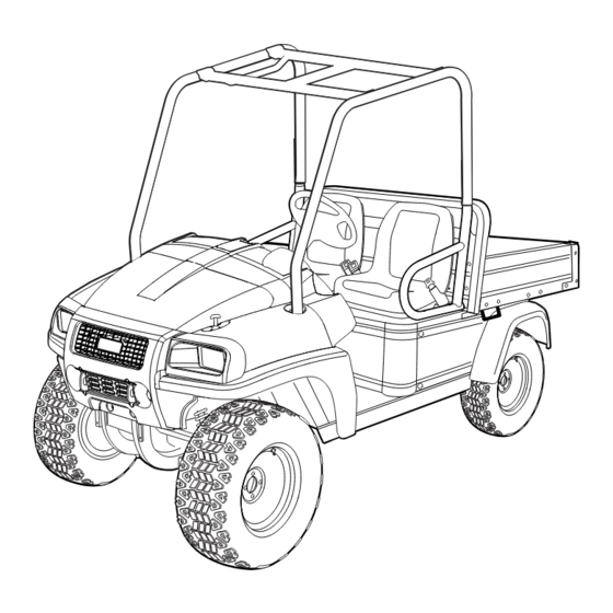
All manuals and user guides at all-guides.com SECTION 3 – GENERAL INFORMATION DANGER • See General Warnings, Section 1, Page 1-2. WARNING • See General Warnings, Section 1, Page 1-2. Throughout this manual, important features unique to each model are highlighted. The manufacturer recommends the owner/operator read and understand this manual and pay special attention to features specific to their vehicle(s). - Page 30 All manuals and user guides at all-guides.com General Warnings GENERAL INFORMATION 1. Hood 2. ROPS 3. Fuel Fill Cap 4. Cargo Bed 5. Bed Lift Latch – vehicles with manual (standard) bed lift only 6. Engine Compartment, Battery, Fuel Tank (under seat; for four-passenger model, engine compartment is under rear seat) 7. Seat 8. Brake Fluid Reservoir (under hood) 9. Radiator and Coolant Reservoir (under hood) –...
-
Page 31: Model Identification - Domestic
All manuals and user guides at all-guides.com GENERAL INFORMATION Model Identification – Domestic MODEL IDENTIFICATION – DOMESTIC The serial number of each vehicle is printed on a bar code decal mounted either below the passenger side cup holder or above the accelerator or brake pedal (Example: PH0901-583947) (Figure 3-4). The two letters (1) at the beginning of the serial number indicate the vehicle model. - Page 32 All manuals and user guides at all-guides.com Model Identification – Domestic GENERAL INFORMATION Figure 3-6 Gasoline Engine Serial Number Location Figure 3-7 Diesel Engine Serial Number Location 2703 Figure 3-8 Differential Serial Number Location Page 3-4 2013 Carryall 295/XRT 1550 Maintenance and Service Manual...
-
Page 33: Model Identification - Homologated
All manuals and user guides at all-guides.com GENERAL INFORMATION Model Identification – Homologated MODEL IDENTIFICATION – HOMOLOGATED The vehicle identification number (Figure 3-9) is located on the center cross bar underneath the bed at the rear of the car . See following NOTE. 1437 Figure 3-9 Vehicle Identification Number Decal NOTE: Have the vehicle identification number available when ordering parts or making inquiries. -
Page 34: Storage
All manuals and user guides at all-guides.com Storage GENERAL INFORMATION STORAGE See General Warnings on page 1-2. DANGER • Do not attempt to drain fuel when the engine is hot or while it is running. • Clean up any spilled fuel before operating the vehicle. •... -
Page 35: Preparing The Vehicle For Extended Storage
All manuals and user guides at all-guides.com GENERAL INFORMATION Storage PREPARING THE VEHICLE FOR EXTENDED STORAGE Unload the vehicle so that the tires are supporting only the weight of the vehicle. Store the vehicle in a cool, dry place. This will minimize battery self-discharge. If the battery appears to be weak, have it charged by a trained technician. -
Page 36: Lifting The Vehicle
All manuals and user guides at all-guides.com Lifting The Vehicle GENERAL INFORMATION Gasoline vehicles only: Completely open the fuel shut-off valve (Figure 3-10, Page 3-6). Ensure the valve is fully open. A partially closed fuel shut-off valve combined with the use of the choke can result in a fouled spark plug and engine failure. -
Page 37: Lifting The Entire Vehicle
All manuals and user guides at all-guides.com GENERAL INFORMATION Lifting The Vehicle Lift rear of vehicle and support on jack stands (Figure 3-12, Page 3-9). See WARNING “Lift only one end...” in General Warnings on page 1-2. 2572 Figure 3-12 Rear Jack Stand Placement LIFTING THE ENTIRE VEHICLE WARNING •... -
Page 38: Using A Booster Battery (Jump Starting)
All manuals and user guides at all-guides.com Using A Booster Battery (Jump Starting) GENERAL INFORMATION USING A BOOSTER BATTERY (JUMP STARTING) WARNING • Wear safety glasses or approved eye protection when servicing the vehicle. Wear a full face shield and rubber gloves when working on or near batteries. - Page 39 All manuals and user guides at all-guides.com GENERAL INFORMATION Using A Booster Battery (Jump Starting) Figure 3-13 Jump Starting 2013 Carryall 295/XRT 1550 Maintenance and Service Manual Page 3-11...
- Page 40 All manuals and user guides at all-guides.com...
-
Page 41: Section 4 - Body And Trim
All manuals and user guides at all-guides.com SECTION 4 – BODY AND TRIM DANGER • See General Warnings, Section 1, Page 1-2. WARNING • See General Warnings, Section 1, Page 1-2. GENERAL INFORMATION The hood, center and side cowl panels are molded-in color, Geloy XTW plastic (except camo finishes and low-volume finishes, such as black, which remain painted but over the closest matching, molded-in color). -
Page 42: Front Body Repair
All manuals and user guides at all-guides.com Front Body Repair BODY AND TRIM Light Soiling – A solution of 10% liquid dish soap and warm water applied with a soft, damp cloth is recommended. A soft bristle brush may be used if necessary. Wipe off any residue with a water dampened cloth. See following NOTE. -
Page 43: Large Scratches And Abrasions
All manuals and user guides at all-guides.com BODY AND TRIM Front Body Components LARGE SCRATCHES AND ABRASIONS Touch-up is not recommended. Replace the entire body part or have it repaired by a professional paint and body repair shop with experience repairing bodies. FRONT BODY COMPONENTS See General Warnings, Section 1, Page 1-2. -
Page 44: Front Fascia Removal
All manuals and user guides at all-guides.com Front Body Components BODY AND TRIM Secure the outside lower ends of the instrument panel using the two hex bolts (these two bolts also help secure the top portion of the front fenders). Secure the outside ends and center of the instrument panel with the three Torx ®... -
Page 45: Center Cowl Panel Installation
All manuals and user guides at all-guides.com BODY AND TRIM Front Body Components The center cowl panel is held in place by four exposed Tuflok plastic locking fasteners and four metal body trim clips that are hidden from view on the top, underside of the panel. Carefully remove the four Tuflok plastic locking screws by using a size P2 Phillips head screwdriver. -
Page 46: Front Fender Flare Removal
All manuals and user guides at all-guides.com Roll-Over Protective Structure (ROPS) BODY AND TRIM Grip the front leading edge of the side cowl panel and twist it towards the center of the vehicle and guide the rear side tab of the side cowl panel into the slot in the front, side of the instrument panel. Engage and secure the three lower side-retaining tabs into the receiving slots on the top of the fender flares. -
Page 47: Rops Removal
All manuals and user guides at all-guides.com BODY AND TRIM Roll-Over Protective Structure (ROPS) WARNING • Do not operate the vehicle if the ROPS is damaged. If the ROPS is damaged, replace the structure. Do not attempt repair. *Four Passenger Vehicles Only 2357 Figure 4-1 Roll-Over Protective Structure (ROPS) –... -
Page 48: Rops Installation
All manuals and user guides at all-guides.com Roll-Over Protective Structure (ROPS) BODY AND TRIM Remove the two hex-head bolts (24) and two flanged lock nuts (25) securing the top brace (23). Remove top brace from vehicle. Remove the hex-head bolts (18) and flanged lock nuts (19) securing the rear support tubes (16) to the rear seat support (17). -
Page 49: Seat
All manuals and user guides at all-guides.com BODY AND TRIM Seat Tighten all hardware to 33 ft-lb (45 N·m). See following WARNING and NOTE. NOTE: If any ROPS joints remain loose, apply additional torque up to 40 ft-lb (54 N·m). WARNING •... -
Page 50: Seat Installation
All manuals and user guides at all-guides.com Seat Belts BODY AND TRIM SEAT INSTALLATION Align the hinges on the underside of the seat front edge with the hinge slots on the frame. Bucket seats 2.1. Push back and down on the seat back to secure the seat latch to the frame. See preceding WARNING. Bench seat 3.1. -
Page 51: Bench Seat Belt Installation
All manuals and user guides at all-guides.com BODY AND TRIM Seat Belts Remove the coiled seat belt assembly. Remove the nut, small washer and two large washers from the seat belt buckle assembly (center location) (Figure 4-3, Page 4-11). Remove the shoulder bolt, spring washer and seat belt buckle assembly. 1446 1447 Figure 4-2 Coiled Seat Belt Assembly... -
Page 52: Seat Belt Installation - Homologated Models
All manuals and user guides at all-guides.com Cargo Bed – Electric Lift BODY AND TRIM 2475 Figure 4-4 Driver Seat Belt – Homologated Models SEAT BELT INSTALLATION – HOMOLOGATED MODELS Driver seat: Install the seat belt buckle assembly and coiled seat belt assembly to the driver seat as shown with hardware previously removed except for the lock nut (Figure 4-4, Page 4-12). -
Page 53: Bed Lift Motor Installation
All manuals and user guides at all-guides.com BODY AND TRIM Cargo Bed – Electric Lift Remove the locknut, bolt, sleeve, spacers and washers from the base of the bed lift motor and vehicle frame and remove the bed lift motor. BED LIFT MOTOR INSTALLATION NOTE: If replacing the actuator, adjust the length of dimension between the base rod hole and the rod end hole using the prior actuator as a guide. -
Page 54: Cargo Bed - Manual Lift
All manuals and user guides at all-guides.com Cargo Bed – Manual Lift BODY AND TRIM CARGO BED – MANUAL LIFT See General Warnings, Section 1, Page 1-2. CARGO BED REMOVAL NOTE: Cargo bed removal and installation will be easier with the aid of an assistant. Raise the bed and ensure that the prop rod is securely engaged. -
Page 55: Rear Fender Installation
All manuals and user guides at all-guides.com BODY AND TRIM Rear Fender 2.2. Grasp the screw head and carefully work the fasteners out to free the top of the fender from the frame. Remove the two Phillips head screws and washers retaining the fender to the side of rear frame. Remove the fender. - Page 56 All manuals and user guides at all-guides.com Rear Fender BODY AND TRIM 1884 Figure 4-5 Cargo Bed Page 4-16 2013 Carryall 295/XRT 1550 Maintenance and Service Manual...
-
Page 57: Section 5 - Accelerator And Brake Pedal Assemblies
All manuals and user guides at all-guides.com SECTION 5 – ACCELERATOR AND BRAKE PEDAL ASSEMBLIES DANGER • See General Warnings, Section 1, Page 1-2. WARNING • See General Warnings, Section 1, Page 1-2. ACCELERATOR PEDAL See General Warnings, Section 1, Page 1-2. ACCELERATOR PEDAL REMOVAL Disconnect battery and spark plug wire(s). -
Page 58: Accelerator Pedal Installation
All manuals and user guides at all-guides.com Accelerator Pedal ACCELERATOR AND BRAKE PEDAL ASSEMBLIES Remove the pedal assembly from the return spring pullrod (3). Loosen spring retaining nut if necessary. AWD only: Remove hardware (4) securing the front differential limit switch (5) to the pedal. Inspect the pedal bushings (6) for wear and replace if worn. -
Page 59: Brake Pedal
All manuals and user guides at all-guides.com ACCELERATOR AND BRAKE PEDAL ASSEMBLIES Brake Pedal BRAKE PEDAL See General Warnings, Section 1, Page 1-2. BRAKE PEDAL REMOVAL Disable the vehicle. See Disabling the Vehicle on page 1-3. Disconnect battery. See Disconnecting the Battery – Gasoline/Diesel Vehicles, Section 1, Page 1-3. Remove the rue pin and the clevis pin. -
Page 60: Park Brake Pedal
All manuals and user guides at all-guides.com Park Brake Pedal ACCELERATOR AND BRAKE PEDAL ASSEMBLIES PARK BRAKE PEDAL See General Warnings, Section 1, Page 1-2. PARK BRAKE PEDAL ASSEMBLY REMOVAL – CABLE ONLY SYSTEM Disconnect battery. See Disconnecting the Battery – Gasoline/Diesel Vehicles, Section 1, Page 1-3. Remove the driver side cup holder to access the cable end at the park brake pedal assembly. - Page 61 All manuals and user guides at all-guides.com ACCELERATOR AND BRAKE PEDAL ASSEMBLIES Park Brake Pedal Secure the cable anchor bracket (5) and park brake pedal assembly with three bolts (3) and locknuts (4). Tighten the locknuts to 15 ft-lb (20 N·m). Connect the cable end to the park brake pedal assembly with bow tie locking pin (1) and clevis pin (2).
- Page 62 All manuals and user guides at all-guides.com...
-
Page 63: Section 6 - Hydraulic And Park Brake Systems
All manuals and user guides at all-guides.com SECTION 6 – HYDRAULIC AND PARK BRAKE SYSTEMS DANGER • See General Warnings, Section 1, Page 1-2. WARNING • See General Warnings, Section 1, Page 1-2. CAUTION • Worn or damaged brake discs cannot be machined to refinish them. Replace as necessary. BRAKE SYSTEM INSPECTION See General Warnings, Section 1, Page 1-2. -
Page 64: Master Cylinder Inspection
All manuals and user guides at all-guides.com Brake System Inspection HYDRAULIC AND PARK BRAKE SYSTEMS MASTER CYLINDER INSPECTION • Inspect the exterior of the master cylinder. Replace any leaking components and bleed the hydraulic brake system. See Bleeding the Hydraulic Brake System on page 6-15. •... -
Page 65: Brake Line Inspection
All manuals and user guides at all-guides.com HYDRAULIC AND PARK BRAKE SYSTEMS Brake System Inspection BRAKE LINE INSPECTION • Inspect the brake lines and fittings for leakage. They must be flexible and free of leaks, cuts, cracks or bulges. Replace as needed. See Hydraulic Line Replacement on page 6-10. •... -
Page 66: Brake System Troubleshooting
All manuals and user guides at all-guides.com Brake System Troubleshooting HYDRAULIC AND PARK BRAKE SYSTEMS BRAKE SYSTEM TROUBLESHOOTING The procedures used in making the checks provided in the following troubleshooting guide can be found in the referenced sections of this maintenance and service manual. TROUBLESHOOTING GUIDE SYMPTOM POSSIBLE CAUSES... - Page 67 All manuals and user guides at all-guides.com HYDRAULIC AND PARK BRAKE SYSTEMS Brake System Troubleshooting TROUBLESHOOTING GUIDE SYMPTOM POSSIBLE CAUSES CORRECTIVE ACTION Replace the brake pads. See Brake Pads Incorrect or distorted brake pads and Caliper on page 6-6. Replace hub, axle seal, or caliper, and replace Grease or brake fluid on the brake pads the brake pads.
-
Page 68: Brake Pads And Caliper
All manuals and user guides at all-guides.com Brake Pads and Caliper HYDRAULIC AND PARK BRAKE SYSTEMS TROUBLESHOOTING GUIDE SYMPTOM POSSIBLE CAUSES CORRECTIVE ACTION Improper park brake adjustment See Park Brake System on page 6-18. Replace the caliper. See Brake Pads and Sticking caliper pistons Caliper on page 6-6. -
Page 69: Brake Pad And Caliper Installation
All manuals and user guides at all-guides.com HYDRAULIC AND PARK BRAKE SYSTEMS Brake Pads and Caliper 2493 Figure 6-2 Front Caliper Banjo Bolt Figure 6-3 Rear Caliper Banjo Bolt Remove the two socket-head slide-pin bolts securing the caliper to its mounting bracket (Figure 6-4, Page 6-7). Pull the caliper off the mounting bracket and remove the pads (Figure 6-5, Page 6-7). - Page 70 All manuals and user guides at all-guides.com Brake Pads and Caliper HYDRAULIC AND PARK BRAKE SYSTEMS WARNING • To reduce the possibility of diminished brake performance or failure, never use petroleum-based lubricants on brake system components, and ensure lubricant does not contact friction surfaces of brake pads or rotors.
-
Page 71: Brake Discs
All manuals and user guides at all-guides.com HYDRAULIC AND PARK BRAKE SYSTEMS Brake Discs 1. Jam Nut 2. Adjustment Bolt 3. O-ring “A” = 1.7 in. (43.2 mm) Maximum 2569 Figure 6-6 Adjustment Bolt – Maximum Distance Out Of Caliper Insert the socket-head slide-pin bolts through the caliper, mounting bracket and brake pads. -
Page 72: Disc Removal
All manuals and user guides at all-guides.com Hydraulic Line Replacement HYDRAULIC AND PARK BRAKE SYSTEMS DISC REMOVAL WARNING • If at any point in this procedure the hydraulic system is opened, the brakes must be bled after the correct reinstallation of the brake components. Failure to bleed the brakes could result in decreased braking performance due to air being trapped in the hydraulic system. -
Page 73: Front Brake Line Removal
All manuals and user guides at all-guides.com HYDRAULIC AND PARK BRAKE SYSTEMS Hydraulic Line Replacement WARNING brakes could result in decreased braking performance due to air being trapped in the hydraulic system. Use only DOT 5 brake fluid. See Bleeding the Hydraulic Brake System on page 6-15. •... -
Page 74: Rear Brake Line Removal
All manuals and user guides at all-guides.com Hydraulic Line Replacement HYDRAULIC AND PARK BRAKE SYSTEMS 2035 2037 Figure 6-7 Front Brake Line T-Bracket Figure 6-8 Front Brake Line Support Brackets Secure the hydraulic lines to the frame above the steering column shaft with wire ties. Install brake lines, new banjo bolts, and new copper washers on each front wheel caliper. -
Page 75: Rear Brake Line Installation
All manuals and user guides at all-guides.com HYDRAULIC AND PARK BRAKE SYSTEMS Hydraulic Line Replacement NOTE: Place a pan under each rear caliper assembly to collect the brake fluid. Place a plastic bag around each caliper to prevent debris from entering the brake line ports. Do not allow brake fluid to contact the brake pads and disc. -
Page 76: Master Cylinder And Reservoir
All manuals and user guides at all-guides.com Master Cylinder and Reservoir HYDRAULIC AND PARK BRAKE SYSTEMS MASTER CYLINDER AND RESERVOIR See General Warnings, Section 1, Page 1-2. FILLING THE HYDRAULIC SYSTEM The brake fluid reservoir is accessible by opening the hood. Do not allow the brake fluid level to fall below the MIN line. -
Page 77: Bleeding The Hydraulic Brake System
All manuals and user guides at all-guides.com HYDRAULIC AND PARK BRAKE SYSTEMS Bleeding the Hydraulic Brake System 2038 Figure 6-9 Master Cylinder Rod and Brake Pedal BLEEDING THE HYDRAULIC BRAKE SYSTEM See General Warnings, Section 1, Page 1-2. WARNING • Do not bleed the brakes in the same manner as a DOT 3 system. Failure to bleed the brakes as instructed in this manual will result in decreased braking performance due to air being trapped in the hydraulic system. - Page 78 All manuals and user guides at all-guides.com Bleeding the Hydraulic Brake System HYDRAULIC AND PARK BRAKE SYSTEMS Vacuum Bleeding: 5.1. Lift and support the vehicle and remove the wheels. See Lifting The Vehicle on page 3-8. 5.2. Connect the vacuum-type brake bleeder (CC P/N S0010702). 5.2.1.
-
Page 79: Purging The Hydraulic System
All manuals and user guides at all-guides.com HYDRAULIC AND PARK BRAKE SYSTEMS Bleeding the Hydraulic Brake System 6.5. Ensure that no brake fluid gets on the brake rotors or pads. If fluid gets on the brake rotors, they should be cleaned with brake cleaner. -
Page 80: Park Brake System
All manuals and user guides at all-guides.com Park Brake System HYDRAULIC AND PARK BRAKE SYSTEMS PARK BRAKE SYSTEM See General Warnings, Section 1, Page 1-2. 1. Jam Nut 2. Adjustment Bolt 3. Caliper Park Brake Lever 2570 Figure 6-10 Rear Caliper – Adjustment Bolt and Park Brake Lever PARK BRAKE ADJUSTMENT –... -
Page 81: Park Brake Wheel Cables
All manuals and user guides at all-guides.com HYDRAULIC AND PARK BRAKE SYSTEMS Park Brake System Chock the wheels, release the park brake, and place the Forward/Reverse handle in the NEUTRAL position. With the park brake released, loosen the hex nuts (1) at the equalizer (2) and then tighten the inner hex nut against the cone (3) and cup (4) washers until significant resistance is observed in the front park brake cable (5) (Figure 6-12, Page 6-19). -
Page 82: Front Park Brake Cable Removal - Cable Only System
All manuals and user guides at all-guides.com Park Brake System HYDRAULIC AND PARK BRAKE SYSTEMS Slide the cable forward to release the sheath ferrule from the caliper bracket. Move the cable up and toward the rear of the vehicle to remove the cable end from the caliper lever. Squeeze the ferrule tines (8) together on the cable end at the frame bracket (7) and remove the cable from the vehicle (Figure 6-12, Page 6-19). -
Page 83: Front Park Brake Cable Installation - Cable Only System
All manuals and user guides at all-guides.com HYDRAULIC AND PARK BRAKE SYSTEMS Park Brake System Disconnect the cable from the threaded adjustment rod by removing the bow tie locking pin (3) and clevis pin (4) (Figure 6-14, Page 6-21). Disconnect the cable end from the park brake pedal assembly by removing the bow tie locking pin (5) and clevis pin (6) (Figure 6-15, Page 6-21). -
Page 84: Park Brake Equalizer Installation - Cable Only System
All manuals and user guides at all-guides.com Park Brake System HYDRAULIC AND PARK BRAKE SYSTEMS PARK BRAKE EQUALIZER INSTALLATION – CABLE ONLY SYSTEM Connect the equalizer (2) to the ends of the rear park brake cables (6 and 8) (Figure 6-12, Page 6-19). Insert the threaded adjustment rod through the equalizer. -
Page 85: Section 7 - Steering And Front Suspension
All manuals and user guides at all-guides.com SECTION 7 – STEERING AND FRONT SUSPENSION DANGER • See General Warnings, Section 1, Page 1-2. WARNING • See General Warnings, Section 1, Page 1-2. STEERING WHEEL See General Warnings, Section 1, Page 1-2. STEERING WHEEL REMOVAL Disconnect battery. -
Page 86: Steering Wheel Installation
All manuals and user guides at all-guides.com Steering Column STEERING AND FRONT SUSPENSION 2478 2043 Figure 7-1 Steering Wheel Removal Figure 7-2 Steering Wheel Puller STEERING WHEEL INSTALLATION Install the steering wheel (3) on the hex portion of the steering shaft. Align the hex fitting of the wheel with the steering column shaft (Figure 7-1, Page 7-2). -
Page 87: Steering Column Installation
All manuals and user guides at all-guides.com STEERING AND FRONT SUSPENSION Rack and Pinion 2044 2045 Figure 7-3 Steering Column Assembly Figure 7-4 Steering Universal Joint STEERING COLUMN INSTALLATION Slide the steering column through the frame opening and down through the hole in the splash guard. Position the steering column against the dash mounting plate, and install new locknuts. -
Page 88: Rack And Pinion Inspection
All manuals and user guides at all-guides.com Rack and Pinion STEERING AND FRONT SUSPENSION RACK AND PINION INSPECTION Look for obvious damage to the chassis, where the rack and pinion is mounted, and the rack and pinion housing. Particularly check the housing for broken mounting points. Compare the toe measurement against the specification. -
Page 89: Rack And Pinion Disassembly
All manuals and user guides at all-guides.com STEERING AND FRONT SUSPENSION Rack and Pinion Slide the universal joint down over the pinion. Align the flat-way on the pinion with the bolt path on the universal joint. Install the universal bolt on the pinion shaft and tighten to 18 ft-lb (24 N·m). See following NOTE. NOTE: Be sure to tighten the bolt at the universal joint on the rack and pinion shaft before tightening the steering column coupling bolt. - Page 90 All manuals and user guides at all-guides.com Rack and Pinion STEERING AND FRONT SUSPENSION Remove both bellows clamps (metal clamps or plastic wire ties) (Figure 7-9, Page 7-6). See following NOTE. NOTE: If the dust seal bellows are secured with a metal clamp, remove the clamp. Do not reuse the clamp when the rack and pinion is reassembled.
- Page 91 All manuals and user guides at all-guides.com STEERING AND FRONT SUSPENSION Rack and Pinion 1. Press Ram 2. Pinion Gear 3. Bearing 2053 2054 Figure 7-12 Remove Pinion from Housing Figure 7-13 Remove Pinion Gear 12. Inspect the bushing (17) and needle bearing (14) for excessive wear. If wear is excessive, replace the complete rack and pinion steering assembly (Figure 7-16, Page 7-8).
- Page 92 All manuals and user guides at all-guides.com Rack and Pinion STEERING AND FRONT SUSPENSION 2057 Figure 7-16 Steering Gear Assembly Page 7-8 2013 Carryall 295/XRT 1550 Maintenance and Service Manual...
-
Page 93: Rack And Pinion Assembly
All manuals and user guides at all-guides.com STEERING AND FRONT SUSPENSION Rack and Pinion RACK AND PINION ASSEMBLY Apply a liberal amount of EP grease to the teeth of the rack (2), then slide the rack through the bushing (17) and housing (1) (Figure 7-16, Page 7-8). -
Page 94: Front Suspension
All manuals and user guides at all-guides.com Front Suspension STEERING AND FRONT SUSPENSION 2060 2061 Figure 7-19 Adjust Rack and Pinion Resistance Figure 7-20 Install Inner Ball Joint 11. Insert a 3/8-inch, 1/4-drive deep-well socket into the steering column end of the universal joint (2), and tighten the bolts (1) to 15 ft-lb (20.3 N·m) (Figure 7-19, Page 7-10). - Page 95 All manuals and user guides at all-guides.com STEERING AND FRONT SUSPENSION Front Suspension Wheel alignment consists of adjusting the toe-in or toe-out and camber of the front wheels. See Toe-in Measurement – Prior to S/N 1309-347765 or any S/N equipped with steering damper accessory on page 7-11. See Toe-Out Measurement –...
- Page 96 All manuals and user guides at all-guides.com Front Suspension STEERING AND FRONT SUSPENSION 2064 Figure 7-23 Adjust Both Drag Links To An Equal Distance Toe-Out Measurement – S/N 1309-347765 and Greater unless equipped with steering damper accessory On a level surface, roll the vehicle forward, then stop. Make sure the front wheels are pointed straight ahead. See following NOTE.
- Page 97 All manuals and user guides at all-guides.com STEERING AND FRONT SUSPENSION Front Suspension NOTE: Do not turn the steering wheel again during this procedure. Use a large carpenter’s square and position it a few inches (cm) away from the center of one wheel (Figure 7-26, Page 7-13).
-
Page 98: Front Suspension Components
All manuals and user guides at all-guides.com Front Suspension Components STEERING AND FRONT SUSPENSION FRONT SUSPENSION COMPONENTS See General Warnings, Section 1, Page 1-2. NOTE: At S/N 1309-347765, changes in front suspension components resulted in new steering uprights, lower A-arms, and camber adjustment bars. These new components add built-in caster and alter toe-adjustment settings. - Page 99 All manuals and user guides at all-guides.com STEERING AND FRONT SUSPENSION Front Suspension Components WARNING • Strain on the brake hose or the brake hose fittings can result in damage to the line or fittings and cause a leak in the hydraulic system, diminished brake performance, or brake failure. •...
-
Page 100: Steering Upright Installation
All manuals and user guides at all-guides.com Front Suspension Components STEERING AND FRONT SUSPENSION CAUTION • Take care when separating the ball joint stud from the upright so as not to tear or puncture the rubber seal around the ball socket. If damaged, the ball joint with rubber boot must be replaced. 16. - Page 101 All manuals and user guides at all-guides.com STEERING AND FRONT SUSPENSION Front Suspension Components Remove the shock absorber. 3.1. Remove the bolt from the bottom mount of the shock absorber, and remove the shock absorber from the A-arm. See following NOTE. NOTE: It may be necessary to place a floor jack under the A-arm assembly and raise it slightly to relieve pressure from the bottom shock absorber bolt.
-
Page 102: Upper A-Arm Installation
All manuals and user guides at all-guides.com Front Suspension Components STEERING AND FRONT SUSPENSION 2070 Figure 7-35 Ball Joint C-Clip UPPER A-ARM INSTALLATION Install a new ball joint if necessary. See Upper Ball Joint Installation on page 7-17. Install new A-arm frame bushings. See following NOTE. NOTE: The urethane bushings fit tightly. -
Page 103: Lower A-Arm Installation
All manuals and user guides at all-guides.com STEERING AND FRONT SUSPENSION Front Suspension Components 2071 2072 Figure 7-36 Lower A-Arm Attachment Figure 7-37 A-Arm Frame Bushings Lower Ball Joint Removal Inspect the ball joint. Replace the ball joint if it is worn, loose, or if the rubber boot is damaged. 1.1. -
Page 104: Front Coil-Over Shock Absorber Removal
All manuals and user guides at all-guides.com Front Suspension Components STEERING AND FRONT SUSPENSION Install a new bolt, washer, and new flanged locknut. Tighten the hardware to 110 ft-lb (148 N·m), applying torque to the bolt side. Repeat steps 1 through 4 for the remaining side if necessary. Align the front wheels. -
Page 105: Front Coil-Over Shock Absorber Installation
All manuals and user guides at all-guides.com STEERING AND FRONT SUSPENSION Front Suspension Components FRONT COIL-OVER SHOCK ABSORBER INSTALLATION NOTE: The standard-duty front coil-over springs and shocks are painted black. Heavy-duty front coil-over springs and shocks have shock housings painted black and springs painted silver. When front shock absorbers are installed, ensure both shock absorbers have identical part numbers. - Page 106 All manuals and user guides at all-guides.com...
-
Page 107: Section 8 - Wheels, Tires And Hubs
All manuals and user guides at all-guides.com SECTION 8 – WHEELS, TIRES AND HUBS DANGER • See General Warnings, Section 1, Page 1-2. WARNING • See General Warnings, Section 1, Page 1-2. GENERAL INFORMATION These vehicles are equipped with either all-terrain or mud tires. The same size tire is used for the front and rear. See Vehicle Specifications on page 2-1. -
Page 108: Wheels
All manuals and user guides at all-guides.com Wheels WHEELS, TIRES AND HUBS NOTE: Small holes in the tire can be plugged with a standard automotive tubeless tire repair kit available at auto supply stores. Tires must be removed and installed from the valve stem side of the rim. WHEELS See General Warnings, Section 1, Page 1-2. -
Page 109: Tire Installation
All manuals and user guides at all-guides.com WHEELS, TIRES AND HUBS Front Hubs TIRE INSTALLATION Use a tire machine to install the new tire on the wheel. See following NOTE. NOTE: When installing mud tires, determine which side of the vehicle they will be used on. The arrow molded on the sidewall indicates designed rotation when vehicle is moving forward (Figure 8-1, Page 8-1). - Page 110 All manuals and user guides at all-guides.com Front Hubs WHEELS, TIRES AND HUBS 1899 Figure 8-2 Position Steel Blocks and Upright on Press Press the bearing out of the upright. 3.1. Position the upright (5) with the two ball joint arms down on one steel block (1) and the drag link arm down on a second steel block (1) (Figure 8-3, Page 8-4).
-
Page 111: Front Hub Installation
All manuals and user guides at all-guides.com WHEELS, TIRES AND HUBS Front Hubs FRONT HUB INSTALLATION WARNING • If at any point in this procedure the hydraulic system is opened, the brakes must be bled after the correct reinstallation of the brake components. Failure to bleed the brakes could result in decreased braking performance due to air being trapped in the hydraulic system. -
Page 112: Rear Hubs
All manuals and user guides at all-guides.com Rear Hubs WHEELS, TIRES AND HUBS 2.4. Use a rod or bar (8) larger than the inner race diameter of the bearing (7) and press the bearing onto the hub until it bottoms out against the shoulder of the hub shaft. The hub shaft should be approximately 3/32 inch (2.38 mm) below the bearing inner race surface (Figure 8-6, Page 8-6). -
Page 113: Rear Hub Installation
All manuals and user guides at all-guides.com WHEELS, TIRES AND HUBS Rear Hubs WARNING • If at any point in this procedure the hydraulic system is opened, the brakes must be bled after the correct reinstallation of the brake components. Failure to bleed the brakes could result in decreased braking performance due to air being trapped in the hydraulic system. - Page 114 All manuals and user guides at all-guides.com Rear Hubs WHEELS, TIRES AND HUBS Install rear brake caliper onto axle tube. See Brake Pad and Caliper Installation on page 6-7. See following NOTE. NOTE: It may be necessary to loosen the park brake adjuster arm on the caliper. Install the tire and wheel and finger-tighten the lug nuts.
-
Page 115: Section 9 - Rear Suspension
All manuals and user guides at all-guides.com SECTION 9 – REAR SUSPENSION DANGER • See General Warnings, Section 1, Page 1-2. WARNING • See General Warnings, Section 1, Page 1-2. REAR COIL-OVER SHOCK ABSORBER See General Warnings, Section 1, Page 1-2. Standard models are equipped with rear shock absorbers and coil-over springs designed for standard-duty service. -
Page 116: Rear Shock Installation
All manuals and user guides at all-guides.com Rear Coil-Over Shock Absorber REAR SUSPENSION 1. Location of brake hose with rubber grommet 2494 Figure 9-1 Rear Shock Absorber Removal REAR SHOCK INSTALLATION Ensure that the adjustment position of the coil spring on the new shock absorber is the same as the previous shock absorber. -
Page 117: Trailing Arms And Lateral Links
All manuals and user guides at all-guides.com REAR SUSPENSION Trailing Arms and Lateral Links TRAILING ARMS AND LATERAL LINKS See General Warnings, Section 1, Page 1-2. LATERAL LINK REMOVAL Disconnect battery and spark plug wire(s). See Disconnecting the Battery – Gasoline/Diesel Vehicles on page 1-3. - Page 118 All manuals and user guides at all-guides.com Trailing Arms and Lateral Links REAR SUSPENSION 2495 Figure 9-2 Rear Suspension Components – 4 Link Page 9-4 2013 Carryall 295/XRT 1550 Maintenance and Service Manual...
-
Page 119: Trailing Arm Removal
All manuals and user guides at all-guides.com REAR SUSPENSION Trailing Arms and Lateral Links TRAILING ARM REMOVAL See General Warnings on page 1-2. Disconnect battery and spark plug wire(s). See Disconnecting the Battery – Gasoline/Diesel Vehicles on page 1-3. Raise the cargo bed. See Body and Trim, Section 4, Page 4-1. Lift and support the rear of vehicle and remove the wheel. - Page 120 All manuals and user guides at all-guides.com...
-
Page 121: Section 10 - Periodic Maintenance
All manuals and user guides at all-guides.com SECTION 10 – PERIODIC MAINTENANCE DANGER • See General Warnings, Section 1, Page 1-2. WARNING • See General Warnings, Section 1, Page 1-2. PERIODIC SERVICE SCHEDULE See General Warnings, Section 1, Page 1-2. WARNING •... - Page 122 All manuals and user guides at all-guides.com Periodic Service Schedule PERIODIC MAINTENANCE PERIODIC SERVICE SCHEDULE REGULAR INTERVAL SERVICE Check engine circulating air passage; visually inspect unshrouded area around engine Engine exhaust for grass and debris and clean if necessary. Diesel vehicles: Check for grass and debris around the radiator.
- Page 123 All manuals and user guides at all-guides.com PERIODIC MAINTENANCE Periodic Service Schedule PERIODIC SERVICE SCHEDULE REGULAR INTERVAL SERVICE Check for loose hardware and tighten if General vehicle necessary. Replace. Dispose of used filters properly. Fuel filters Check safety decals. Replace if damaged or Safety decals illegible.
-
Page 124: Periodic Service Schedule - Intellitach
All manuals and user guides at all-guides.com Periodic Service Schedule – IntelliTach PERIODIC MAINTENANCE PERIODIC SERVICE SCHEDULE – INTELLITACH WARNING • Service, repairs, and adjustments must be made per instructions in the appropriate maintenance and service manual. NOTE: If the vehicle is constantly subjected to heavy use or severe operating conditions, these preventive maintenance procedures should be performed more often than recommended in the Periodic Service and Lubrication Schedules. - Page 125 All manuals and user guides at all-guides.com PERIODIC MAINTENANCE Periodic Service Schedule – IntelliTach PERIODIC SERVICE SCHEDULE REGULAR INTERVAL SERVICE Battery Clean terminals and wash dirt from casing; check electrolyte level. Add distilled water if necessary. See page . Front wheel alignment and toe-in Check and adjust if necessary.
-
Page 126: Periodic Lubrication Schedule
All manuals and user guides at all-guides.com Periodic Lubrication Schedule PERIODIC MAINTENANCE PERIODIC LUBRICATION SCHEDULE PERIODIC LUBRICATION SCHEDULE LUBRICATION REGULAR INTERVAL SERVICE RECOMMENDED LUBRICANT POINTS Gasoline vehicle: Kawasaki engine- First change 10 hours Gasoline (Kawasaki engine) vehicles: Diesel vehicle: First change 1 qt. - Page 127 All manuals and user guides at all-guides.com PERIODIC MAINTENANCE Periodic Lubrication Schedule Figure 10-2 Lubrication Points – Diesel Vehicles 2013 Carryall 295/XRT 1550 Maintenance and Service Manual Page 10-7...
-
Page 128: Periodic Lubrication Schedule - Intellitach
All manuals and user guides at all-guides.com Periodic Lubrication Schedule – IntelliTach PERIODIC MAINTENANCE PERIODIC LUBRICATION SCHEDULE – INTELLITACH PERIODIC LUBRICATION SCHEDULE LUBRICATION REGULAR INTERVAL SERVICE RECOMMENDED LUBRICANT POINTS Diesel vehicle: First change 50 hours – additional change Diesel vehicles: 3 qt. (2.8 L) with filter. See for both every 100 hours of Change engine oil and oil filter Oil Viscosity on page 10-14. -
Page 129: Lubricating The Attachment Arm And Interface - Intellitach
All manuals and user guides at all-guides.com PERIODIC MAINTENANCE Lubricating the Attachment Arm and Interface – IntelliTach LUBRICATING THE ATTACHMENT ARM AND INTERFACE – INTELLITACH Always use a good quality, lithium-based, multi-purpose grease. Apply lubricant until extra grease shows. Grease the 8 grease fittings every 50 hours of operation, 2 times a year (whichever occurs first) or whenever the attachment arm and interface are removed and reinstalled on the vehicle. -
Page 130: Brake Fluid Reservoir
All manuals and user guides at all-guides.com Brake Fluid Reservoir PERIODIC MAINTENANCE BRAKE FLUID RESERVOIR 1. Full Level 2. Safe Level 3. Low Level 2692 2693 Figure 10-5 Brake Fluid and Coolant Access (diesel only) Figure 10-6 Brake Fluid Reservoir Level The brake fluid reservoir (1) is located under the hood. -
Page 131: Oil Pressure - Gasoline Engine
All manuals and user guides at all-guides.com PERIODIC MAINTENANCE Engine Oil OIL PRESSURE – GASOLINE ENGINE Kawasaki engine: The Kawasaki gasoline engine has an oil filter that is mounted on a bracket between and in front of the engine and transmission. Inlet and outlet oil-carrying hoses enable oil circulation to and from the engine. See following NOTE. - Page 132 All manuals and user guides at all-guides.com Engine Oil PERIODIC MAINTENANCE After that, the oil should be changed every 100 hours of operation or annually, whichever comes first. Engine Oil Draining Turn the key switch to the OFF position and remove the key. Place the Forward/Reverse handle in the NEUTRAL position.
- Page 133 All manuals and user guides at all-guides.com PERIODIC MAINTENANCE Engine Oil Figure 10-11 Replace Engine Oil Filter – Kawasaki Gasoline Vehicles Engine Oil Filter Change Drain the engine oil. See Engine Oil Draining on page 10-12. Place the oil drain pan under the engine oil filter (2) (Figure 10-10 or Figure 10-11). Remove the engine oil filter.
-
Page 134: Oil Viscosity
All manuals and user guides at all-guides.com Engine Oil PERIODIC MAINTENANCE Figure 10-14 Add Engine Oil – Gasoline Vehicles Figure 10-15 Add Engine Oil – Diesel Vehicles Engine Oil Filling Add engine oil (Figure 10-14 or Figure 10-15). With filter change, the engine requires the following amounts: –... -
Page 135: Spark Plugs
All manuals and user guides at all-guides.com PERIODIC MAINTENANCE Spark Plugs Gasoline Vehicles Only: Below 40°F (4°C), the use of SAE 30 may result in hard starting. Gasoline Vehicles Only: Above 80°F (27°C), the use of 10W-30 may cause increased oil consumption. Check oil level more frequently. -
Page 136: Lubrication Change For Front Differential, Transmission And Rear Differential
All manuals and user guides at all-guides.com Gearcase Lubrication PERIODIC MAINTENANCE Figure 10-18 Front Differential Level Indicator, Fill and Drain Plug Transmission: When the vehicle is on a level surface, use the level indicator hole (1) as a lubricant level indicator (Figure 10-19). Lubricant level should be even with the bottom of level indicator hole (1). - Page 137 All manuals and user guides at all-guides.com PERIODIC MAINTENANCE Gearcase Lubrication 1. Fill Plug 2. Drain Plug 1. Lubricant Level Indicator 2. Drain Plug 3. Fill Plug 2558 2480 Figure 10-19 Transmission Level Indicator, Fill and Drain Figure 10-20 Rear Differential Fill and Drain Plugs Plugs Front differential: Clean and install the drain plug (2) and washer before filling the front differential with new lubricant (Figure 10-18).
-
Page 138: Hydraulic System - Intellitach Vehicle
All manuals and user guides at all-guides.com Hydraulic System – IntelliTach Vehicle PERIODIC MAINTENANCE HYDRAULIC SYSTEM – INTELLITACH VEHICLE WARNING • Diesel fuel or hydraulic fluid under pressure can penetrate skin or eyes, causing serious injury or death. Fluid leaks under pressure may not be visible. Use a piece of cardboard or wood to find leaks. Do not use your bare hand. -
Page 139: Engine Coolant Level Check
All manuals and user guides at all-guides.com PERIODIC MAINTENANCE Fueling Instructions ENGINE COOLANT LEVEL CHECK The coolant reserve tank (2) is located under the hood on the passenger side (Figure 10-5, Page 10-10). Raise the hood to check the coolant level before every operation. Check the coolant level of the reserve tank (2). -
Page 140: Biodiesel Fuel (Diesel Vehicles Only)
All manuals and user guides at all-guides.com Fueling Instructions PERIODIC MAINTENANCE Figure 10-23 Fuel Tank – Gasoline Vehicles Figure 10-24 Fuel Tank – Diesel Vehicles BIODIESEL FUEL (DIESEL VEHICLES ONLY) Biodiesel has unique qualities that should be considered before it is used in the Kubota D722 diesel engine. During cold weather, plugged fuel lines, plugged fuel systems, hard starting, and other unknown failures can result from use of this fuel. -
Page 141: Draining Water From Fuel Filter
All manuals and user guides at all-guides.com PERIODIC MAINTENANCE Fueling Instructions • Check the engine oil level daily before the engine is started. See Engine Oil Level Check on page 10-11. • Before vehicle storage, run the engine with conventional diesel fuel for at least 30 minutes to flush the biodiesel from the engine. -
Page 142: Battery
All manuals and user guides at all-guides.com Battery PERIODIC MAINTENANCE BATTERY For periodic battery maintenance, see Battery on page 13-18 (gasoline vehicles) or page 14-21 (diesel vehicles). Page 10-22 2013 Carryall 295/XRT 1550 Maintenance and Service Manual... -
Page 143: Section 11 - Troubleshooting And Electrical System: Gasoline Vehicles
All manuals and user guides at all-guides.com SECTION 11 – TROUBLESHOOTING AND ELECTRICAL SYSTEM: GASOLINE VEHICLES DANGER • See General Warnings, Section 1, Page 1-2. WARNING • See General Warnings, Section 1, Page 1-2. TROUBLESHOOTING GUIDE The following troubleshooting guide will be helpful in identifying operating difficulties should they occur. The guide includes the symptom, probable cause(s) and suggested checks. - Page 144 All manuals and user guides at all-guides.com TROUBLESHOOTING AND ELECTRICAL Troubleshooting Guide SYSTEM: GASOLINE VEHICLES TROUBLESHOOTING GUIDE SYMPTOM POSSIBLE CAUSES REFER TO Spark plug is fouled or in poor condition Spark Plugs on page 10-15 See the Kawasaki FH680D engine manual Spark plug wire is damaged or loose (CC P/N 103351201).
- Page 145 All manuals and user guides at all-guides.com TROUBLESHOOTING AND ELECTRICAL SYSTEM: GASOLINE VEHICLES Troubleshooting Guide TROUBLESHOOTING GUIDE SYMPTOM POSSIBLE CAUSES REFER TO See the Kawasaki FH680D engine manual Exhaust valve is restricted with carbon deposit (CC P/N 103351201). Muffler or exhaust pipe restricted with carbon Exhaust System on page 15-6 or other substance Test Procedure 21 –...
- Page 146 All manuals and user guides at all-guides.com TROUBLESHOOTING AND ELECTRICAL Troubleshooting Guide SYSTEM: GASOLINE VEHICLES TROUBLESHOOTING GUIDE SYMPTOM POSSIBLE CAUSES REFER TO Test Procedure 6 – Starter Control Circuit on Starter control circuit is not operating page 11-14 Start relay failure Test Procedure 7 –...
- Page 147 All manuals and user guides at all-guides.com TROUBLESHOOTING AND ELECTRICAL SYSTEM: GASOLINE VEHICLES Troubleshooting Guide TROUBLESHOOTING GUIDE SYMPTOM POSSIBLE CAUSES REFER TO See Section 15 – Gasoline Engine, Muffler, Engine mounting nuts or bolts are loose Fuel System, and Clutches. Misaligned muffler mounting clamp Exhaust System on page 15-6 Damaged drive belt...
-
Page 148: Wiring Diagram
All manuals and user guides at all-guides.com TROUBLESHOOTING AND ELECTRICAL Wiring Diagram SYSTEM: GASOLINE VEHICLES WIRING DIAGRAM DIODE 3 DIODE 2 DIODE 1 FRONT DIFFERENT IAL LIMIT SWITCH WD1033057-7-L NOTE: AWD diagram shown; 2-wheel drive vehicle uses same harness Figure 11-1 Wiring Diagram – Front Page 11-6 2013 Carryall 295/XRT 1550 Maintenance and Service Manual... - Page 149 All manuals and user guides at all-guides.com TROUBLESHOOTING AND ELECTRICAL SYSTEM: GASOLINE VEHICLES Wiring Diagram DIODE 4 DIODE 5 WD1033057-7-R NOTE: AWD diagram shown; 2-wheel drive vehicle uses same harness Figure 11-2 Wiring Diagram – Rear 2013 Carryall 295/XRT 1550 Maintenance and Service Manual Page 11-7...
-
Page 150: Test Procedures
All manuals and user guides at all-guides.com TROUBLESHOOTING AND ELECTRICAL Test Procedures SYSTEM: GASOLINE VEHICLES TEST PROCEDURES Index of Test Procedures 1 – Battery 2 – Fuse 3 – Ground Cables 4 – Key Switch (ON Position) 5 – Key Switch (Starter Circuit) 6 –... - Page 151 All manuals and user guides at all-guides.com TROUBLESHOOTING AND ELECTRICAL SYSTEM: GASOLINE VEHICLES Test Procedures DANGER rubber gloves when working on or near batteries. For added protection, cover top of the battery when servicing the vehicle. • Battery – Poison! Contains acid! Causes severe burns! Avoid contact with skin, eyes, or clothing. –...
- Page 152 All manuals and user guides at all-guides.com TROUBLESHOOTING AND ELECTRICAL Test Procedures SYSTEM: GASOLINE VEHICLES 1.250 1.280 1. Level Indicator 2. Cap 3. Plates Electrolyte level at least 1/2 inch (13 MM) above plates or to level indicator. View at eye level. Figure 11-3 Hydrometer Test Figure 11-4 Battery Electrolyte Level Hydrometer Calibration...
- Page 153 All manuals and user guides at all-guides.com TROUBLESHOOTING AND ELECTRICAL SYSTEM: GASOLINE VEHICLES Test Procedures Load Test NOTE: Ensure that the battery is fully charged before performing the following test procedure. Disable the vehicle. See Disabling the Vehicle on page 1-3. Check for loose or corroded battery terminal connections.
- Page 154 All manuals and user guides at all-guides.com TROUBLESHOOTING AND ELECTRICAL Test Procedures SYSTEM: GASOLINE VEHICLES 2081 Figure 11-5 Electrical Component Mounting Plate TEST PROCEDURE 3 – Ground Cables See General Warnings, Section 1, Page 1-2. Disconnect battery and spark plug wire(s). See Disconnecting the Battery – Gasoline/Diesel Vehicles on page 1-3.
- Page 155 All manuals and user guides at all-guides.com TROUBLESHOOTING AND ELECTRICAL SYSTEM: GASOLINE VEHICLES Test Procedures 2082 2083 Figure 11-6 Frame Ground Figure 11-7 Engine Ground to Frame TEST PROCEDURE 4 – Key Switch (ON Position) See General Warnings, Section 1, Page 1-2. Disconnect battery and spark plug wire(s).
- Page 156 All manuals and user guides at all-guides.com TROUBLESHOOTING AND ELECTRICAL Test Procedures SYSTEM: GASOLINE VEHICLES Ensure that the key switch connector is connected correctly and is tight. If it is not, repair or replace as necessary. Remove the key switch. See Key Switch Removal on page 13-8. Set the multimeter to 200 ohms.
- Page 157 All manuals and user guides at all-guides.com TROUBLESHOOTING AND ELECTRICAL SYSTEM: GASOLINE VEHICLES Test Procedures – Check diode 5. See Test Procedure 14 – Diode 5 on wire 131 and 129 on page 11-21. – Check the neutral switch on the transmission housing. See Test Procedure 15 – Neutral Switch (Transmission) on page 11-23.
- Page 158 All manuals and user guides at all-guides.com TROUBLESHOOTING AND ELECTRICAL Test Procedures SYSTEM: GASOLINE VEHICLES 2085 2086 Figure 11-10 Start Relay Coil Circuit Test Figure 11-11 Start Relay Contact Test If the reading obtained in step 5 is not 12 VDC with the key in the START position, perform the following test procedures: –...
- Page 159 All manuals and user guides at all-guides.com TROUBLESHOOTING AND ELECTRICAL SYSTEM: GASOLINE VEHICLES Test Procedures 2087 2088 Figure 11-12 Carburetor Heater Relay Coil Circuit Test Figure 11-13 Carburetor Heater Relay Contact Test If the reading is 12 VDC and the relay clicks when the engine starts, check the relay contacts. 6.1.
- Page 160 All manuals and user guides at all-guides.com TROUBLESHOOTING AND ELECTRICAL Test Procedures SYSTEM: GASOLINE VEHICLES TEST PROCEDURE 9 – Wire Harness Diodes See General Warnings, Section 1, Page 1-2. A diode is designed to conduct current in one direction only. Depending on the application, diodes are used in the vehicle to control electrical system logic, or to help protect relay and switch contacts from excessive arcing.
- Page 161 All manuals and user guides at all-guides.com TROUBLESHOOTING AND ELECTRICAL SYSTEM: GASOLINE VEHICLES Test Procedures DIODE TROUBLESHOOTING GUIDE IN-LINE WIRE FAILURE DIODE LOCATION FUNCTION SYMPTOM/COMMENT CONDITION (WIRES) Will contribute to the premature failure Open of the limit switch (switch is only used Front differential coil flyback diode in AWD vehicle).
- Page 162 All manuals and user guides at all-guides.com TROUBLESHOOTING AND ELECTRICAL Test Procedures SYSTEM: GASOLINE VEHICLES If the readings obtained in the previous steps are incorrect, replace the diode. See Wire Harness Diode Removal on page 13-18. TEST PROCEDURE 11 – Diode 2 on wire 40 and 41 See General Warnings, Section 1, Page 1-2.
- Page 163 All manuals and user guides at all-guides.com TROUBLESHOOTING AND ELECTRICAL SYSTEM: GASOLINE VEHICLES Test Procedures Remove the starter relay, carburetor heater relay and, if equipped, the accessory relay from the multi-pin connector located on the electrical component mounting plate. Set the multimeter to the diode test function. Connect the black (–) probe of the multimeter to the 18-gauge purple wire (w47) at the key switch multi-pin connector.
- Page 164 All manuals and user guides at all-guides.com TROUBLESHOOTING AND ELECTRICAL Test Procedures SYSTEM: GASOLINE VEHICLES Reverse the multimeter probes and note the reading. The multimeter should indicate approximately 540 mV, however, a range of 400 to 700 mV is acceptable. 10.
- Page 165 All manuals and user guides at all-guides.com TROUBLESHOOTING AND ELECTRICAL SYSTEM: GASOLINE VEHICLES Test Procedures TEST PROCEDURE 15 – Neutral Switch (Transmission) See General Warnings, Section 1, Page 1-2. The neutral switch is located on the transmission housing. Disconnect battery and spark plug wire(s). See Disconnecting the Battery – Gasoline/Diesel Vehicles on page 1-3.
- Page 166 All manuals and user guides at all-guides.com TROUBLESHOOTING AND ELECTRICAL Test Procedures SYSTEM: GASOLINE VEHICLES Check for continuity on the switch contacts with the Forward/Reverse handle in the REVERSE position (Figure 11-19, Page 11-23). The multimeter should indicate no continuity. If any of the continuity readings are incorrect, replace the neutral switch.
- Page 167 All manuals and user guides at all-guides.com TROUBLESHOOTING AND ELECTRICAL SYSTEM: GASOLINE VEHICLES Test Procedures Check for proper wiring and tight connections at the front differential limit switch (Figure 11-20, Page 11-24). Move the accelerator pedal and listen for an audible click from the switch. If there is no click, check the limit switch for proper alignment and switch arm movement.
- Page 168 All manuals and user guides at all-guides.com TROUBLESHOOTING AND ELECTRICAL Test Procedures SYSTEM: GASOLINE VEHICLES TEST PROCEDURE 20 – Voltage Regulator See General Warnings, Section 1, Page 1-2. NOTE: Keep the battery connected during this test procedure. Disable the vehicle. See Disabling the Vehicle on page 1-3. Ensure that the wires are connected correctly and are tight.
- Page 169 All manuals and user guides at all-guides.com TROUBLESHOOTING AND ELECTRICAL SYSTEM: GASOLINE VEHICLES Test Procedures Connect the red (+) probe of the multimeter to the white/black wire terminal of the six wire connector and connect the black (–) probe to the vehicle frame (ground). The multimeter should indicate continuity with the key switch in the OFF position.
- Page 170 All manuals and user guides at all-guides.com TROUBLESHOOTING AND ELECTRICAL Test Procedures SYSTEM: GASOLINE VEHICLES TEST PROCEDURE 24 – Key Switch (Engine Kill Circuit) See General Warnings, Section 1, Page 1-2. Disconnect battery and spark plug wire(s). See Disconnecting the Battery – Gasoline/Diesel Vehicles on page 1-3.
- Page 171 All manuals and user guides at all-guides.com TROUBLESHOOTING AND ELECTRICAL SYSTEM: GASOLINE VEHICLES Test Procedures TEST PROCEDURE 26 – Reverse Warning Buzzer (If Equipped) See General Warnings, Section 1, Page 1-2. Disconnect battery and spark plug wire(s). See Disconnecting the Battery – Gasoline/Diesel Vehicles on page 1-3.
- Page 172 All manuals and user guides at all-guides.com TROUBLESHOOTING AND ELECTRICAL Test Procedures SYSTEM: GASOLINE VEHICLES 2089 Figure 11-25 Carburetor Solenoid Bullet Connector TEST PROCEDURE 28 – Low Oil Warning Light Circuit See General Warnings, Section 1, Page 1-2. If the low oil warning light stays on, test the oil pressure switch. See the Kawasaki FH680D engine manual (CC P/N 103351201).
- Page 173 All manuals and user guides at all-guides.com TROUBLESHOOTING AND ELECTRICAL SYSTEM: GASOLINE VEHICLES Test Procedures TEST PROCEDURE 29 – 12-Volt Accessory Receptacle See General Warnings, Section 1, Page 1-2. NOTE: Keep the battery connected during this test procedure. Disable the vehicle. See Disabling the Vehicle on page 1-3. Set the multimeter to 20 VDC.
- Page 174 All manuals and user guides at all-guides.com TROUBLESHOOTING AND ELECTRICAL Test Procedures SYSTEM: GASOLINE VEHICLES FLOAT POSITION RESISTANCE READING FUEL GAUGE READINGS Lower position (tank empty) 240 ±20 ohms Empty Center position (tank half full) 120 ±20 ohms Half full Upper position (tank full) 60 ±20 ohms Full...
- Page 175 All manuals and user guides at all-guides.com TROUBLESHOOTING AND ELECTRICAL SYSTEM: GASOLINE VEHICLES Test Procedures The orange wire should remain disconnected for this step. Place the black probe of the multimeter on the (1) terminal of the fuel gauge/hour meter and place the red (+) probe on the (4) terminal of the fuel gauge/hour meter (Figure 11-29, Page 11-33).
- Page 176 All manuals and user guides at all-guides.com TROUBLESHOOTING AND ELECTRICAL Test Procedures SYSTEM: GASOLINE VEHICLES Use a multimeter set to 20 volts DC and place alligator clips on the multimeter probes. Connect the red (+) probe to the light switch terminal where the blue wire (w03) is connected (Figure 11-30, Page 11-34). WAVETEK 1000 2000...
- Page 177 All manuals and user guides at all-guides.com TROUBLESHOOTING AND ELECTRICAL SYSTEM: GASOLINE VEHICLES Test Procedures WAVETEK 1000 2000 200k 200nA 1000 --- FUSED 750V Figure 11-31 Voltage Measurement at Headlight Socket If there is no voltage reading at the wire harness, check the continuity of the 16-gauge blue wires (w01 and w03) from the headlight to the light switch.
- Page 178 All manuals and user guides at all-guides.com TROUBLESHOOTING AND ELECTRICAL Test Procedures SYSTEM: GASOLINE VEHICLES 2102 2103 Figure 11-33 Bed Lift Motor Voltage Reading with Switch Figure 11-34 Bed Lift Motor Voltage Reading with Switch in UP position in DOWN position TEST PROCEDURE 35 –...
- Page 179 All manuals and user guides at all-guides.com TROUBLESHOOTING AND ELECTRICAL SYSTEM: GASOLINE VEHICLES Test Procedures TEST PROCEDURE 36 – Bed Lift Switch Remove the bed lift switch. See Bed Lift Switch Removal on page 13-10. Check continuity between the terminals (Figure 11-35, Page 11-37) of the switch and compare the readings with the Bed Lift Switch Continuity Table.
- Page 180 All manuals and user guides at all-guides.com...
-
Page 181: Section 12 - Troubleshooting And Electrical System: Diesel Vehicles
All manuals and user guides at all-guides.com SECTION 12 – TROUBLESHOOTING AND ELECTRICAL SYSTEM: DIESEL VEHICLES DANGER • See General Warnings, Section 1, Page 1-2. WARNING • See General Warnings, Section 1, Page 1-2. TROUBLESHOOTING GUIDE The following troubleshooting guide will be helpful in identifying operating difficulties should they occur. The guide includes the symptom, probable cause(s) and suggested checks. - Page 182 All manuals and user guides at all-guides.com TROUBLESHOOTING AND ELECTRICAL Troubleshooting Guide SYSTEM: DIESEL VEHICLES TROUBLESHOOTING GUIDE SYMPTOM POSSIBLE CAUSES REFER TO Test Procedure 27 – Fuel Solenoid Pull Coil Fuel solenoid failure Circuit on page 12-35 and Test Procedure 28 – Fuel Solenoid Hold Coil Circuit on page 12-35 Improper idle governor adjustment Idle RPM Adjustment on page 16-20...
- Page 183 All manuals and user guides at all-guides.com TROUBLESHOOTING AND ELECTRICAL SYSTEM: DIESEL VEHICLES Troubleshooting Guide TROUBLESHOOTING GUIDE SYMPTOM POSSIBLE CAUSES REFER TO Uneven fuel injection Poor injection nozzle performance Oil level is low Add engine oil. See owner’s manual. See the Kubota D722 diesel engine manual Oil level sensor failure Low oil warning light stays on.
- Page 184 All manuals and user guides at all-guides.com TROUBLESHOOTING AND ELECTRICAL Troubleshooting Guide SYSTEM: DIESEL VEHICLES TROUBLESHOOTING GUIDE SYMPTOM POSSIBLE CAUSES REFER TO Oil ring worn Piston ring groove worn See the Kubota D722 diesel engine manual Excessive engine oil consumption. (CC P/N 103840201).
- Page 185 All manuals and user guides at all-guides.com TROUBLESHOOTING AND ELECTRICAL SYSTEM: DIESEL VEHICLES Troubleshooting Guide TROUBLESHOOTING GUIDE SYMPTOM POSSIBLE CAUSES REFER TO Test Procedure 20 – Front Drive Gearcase Failed front drive gearcase engagement coil Coil on page 12-30 Test Procedure 19 – Front Differential Limit Failed differential limit switch Switch on page 12-29 Front differential does not engage front wheels.
-
Page 186: Wiring Diagram
All manuals and user guides at all-guides.com TROUBLESHOOTING AND ELECTRICAL Wiring Diagram SYSTEM: DIESEL VEHICLES WIRING DIAGRAM FUEL GAUGE/ HOUR METER FRONT DIFFERENTIAL LIMIT S WITCH WD1032775E7-L Figure 12-1 Wiring Diagram for Diesel Utility Vehicles (Front) Page 12-6 2013 Carryall 295/XRT 1550 Maintenance and Service Manual... - Page 187 All manuals and user guides at all-guides.com TROUBLESHOOTING AND ELECTRICAL SYSTEM: DIESEL VEHICLES Wiring Diagram LIGHTING RELAY WD1032775E7-R Figure 12-2 Wiring Diagram for Diesel Utility Vehicles (Rear) 2013 Carryall 295/XRT 1550 Maintenance and Service Manual Page 12-7...
- Page 188 All manuals and user guides at all-guides.com TROUBLESHOOTING AND ELECTRICAL Wiring Diagram SYSTEM: DIESEL VEHICLES WD1033181B3 Figure 12-3 Main Light Wiring Diagram – Carryall 295 Homologated Vehicle Page 12-8 2013 Carryall 295/XRT 1550 Maintenance and Service Manual...
- Page 189 All manuals and user guides at all-guides.com TROUBLESHOOTING AND ELECTRICAL SYSTEM: DIESEL VEHICLES Wiring Diagram WD1033173B4 Figure 12-4 High Beam Wiring Diagram – Carryall 295 Homologated Vehicle 2013 Carryall 295/XRT 1550 Maintenance and Service Manual Page 12-9...
-
Page 190: Test Procedures
All manuals and user guides at all-guides.com TROUBLESHOOTING AND ELECTRICAL Test Procedures SYSTEM: DIESEL VEHICLES TEST PROCEDURES Index of Test Procedures 1 – Battery 2 – Fuse 3 – Ground Cables 4 – Key Switch (Starter Circuit) 5 – Key Switch (ON Position) 6 –... - Page 191 All manuals and user guides at all-guides.com TROUBLESHOOTING AND ELECTRICAL SYSTEM: DIESEL VEHICLES Test Procedures DANGER • Battery – Explosive gases! Do not smoke. Keep sparks and flames away from the vehicle and service area. Ventilate when charging or using in an enclosed space. Wear a full face shield and rubber gloves when working on or near batteries.
- Page 192 All manuals and user guides at all-guides.com TROUBLESHOOTING AND ELECTRICAL Test Procedures SYSTEM: DIESEL VEHICLES 1.250 1.280 1. Level Indicator 2. Cap 3. Plates Electrolyte level at least 1/2 inch (13 MM) above plates or to level indicator. View at eye level. Figure 12-5 Hydrometer Test Figure 12-6 Battery Electrolyte Level Hydrometer Calibration...
- Page 193 All manuals and user guides at all-guides.com TROUBLESHOOTING AND ELECTRICAL SYSTEM: DIESEL VEHICLES Test Procedures Load Test NOTE: Ensure that the battery is fully charged before performing the following test procedure. Disable the vehicle. See Disabling the Vehicle on page 1-3. Check for loose or corroded battery terminal connections.
- Page 194 All manuals and user guides at all-guides.com TROUBLESHOOTING AND ELECTRICAL Test Procedures SYSTEM: DIESEL VEHICLES 2105 Figure 12-7 Electrical Component Mounting Plate TEST PROCEDURE 3 – Ground Cables See General Warnings, Section 1, Page 1-2. Disconnect battery. See Disconnecting the Battery – Gasoline/Diesel Vehicles, Section 1, Page 1-3. Check the frame ground connection for loose connections and damaged terminals (Figure 12-8, Page 12-15).
- Page 195 All manuals and user guides at all-guides.com TROUBLESHOOTING AND ELECTRICAL SYSTEM: DIESEL VEHICLES Test Procedures 2106 2107 Figure 12-8 Frame Ground Figure 12-9 Engine Ground (Under Starter) TEST PROCEDURE 4 – Key Switch (Starter Circuit) See General Warnings, Section 1, Page 1-2. Disconnect battery.
- Page 196 All manuals and user guides at all-guides.com TROUBLESHOOTING AND ELECTRICAL Test Procedures SYSTEM: DIESEL VEHICLES 6.1. Use alligator clips to connect the multimeter probes between the B and I terminals. With the key in the START position, the multimeter should indicate continuity (Figure 12-10, Page 12-15). If the multimeter does not indicate continuity, the key switch has failed and should be replaced.
- Page 197 All manuals and user guides at all-guides.com TROUBLESHOOTING AND ELECTRICAL SYSTEM: DIESEL VEHICLES Test Procedures TEST PROCEDURE 7 – Starter Control Circuit See General Warnings, Section 1, Page 1-2. Disable the vehicle. See Disabling the Vehicle on page 1-3. Disconnect the 16-gauge green wire (w127) from the starter solenoid coil to prevent the vehicle from unintentionally starting (Figure 12-11, Page 12-17).
- Page 198 All manuals and user guides at all-guides.com TROUBLESHOOTING AND ELECTRICAL Test Procedures SYSTEM: DIESEL VEHICLES 2111 2112 Figure 12-13 Start Relay Coil Circuit Test Figure 12-14 Start Relay Contact Test TEST PROCEDURE 8 – Start Relay See General Warnings, Section 1, Page 1-2. Disable the vehicle.
- Page 199 All manuals and user guides at all-guides.com TROUBLESHOOTING AND ELECTRICAL SYSTEM: DIESEL VEHICLES Test Procedures – Check the 30-amp fuse (on w125). See Test Procedure 2 – Fuse on page 12-13. – Check the key switch. See Test Procedure 4 – Key Switch (Starter Circuit) on page 12-15. –...
- Page 200 All manuals and user guides at all-guides.com TROUBLESHOOTING AND ELECTRICAL Test Procedures SYSTEM: DIESEL VEHICLES 2113 2114 Figure 12-15 Check Power To Fan Relay Figure 12-16 Fan Relay Contact Test If the fan runs constantly, even with the key switch OFF, remove the relay. If fan stops, the relay contacts have failed closed and the relay must be replaced.
- Page 201 All manuals and user guides at all-guides.com TROUBLESHOOTING AND ELECTRICAL SYSTEM: DIESEL VEHICLES Test Procedures 4.1. Set a multimeter to 200 ohms. 4.2. Use an alligator clip to connect the black (–) probe of the multimeter to the frame (ground). 4.3.
- Page 202 All manuals and user guides at all-guides.com TROUBLESHOOTING AND ELECTRICAL Test Procedures SYSTEM: DIESEL VEHICLES WARNING • Allow surfaces to cool adequately before touching them. 2116 Figure 12-18 Fan Thermostat Switch Test Setup TEST PROCEDURE 11 – Fan Motor See General Warnings, Section 1, Page 1-2. The fan relay activates the radiator fan when the engine coolant reaches a temperature range of 187 °F to 198 °F (86 °C to 92 °C) and closes the fan thermostat switch.
- Page 203 All manuals and user guides at all-guides.com TROUBLESHOOTING AND ELECTRICAL SYSTEM: DIESEL VEHICLES Test Procedures 2117 2118 Figure 12-19 Fan Motor Connector Figure 12-20 Thermostat Switch Connector Connect the battery cables, positive (+) cable first. Leave the Forward/Reverse handle in the NEUTRAL position. 10.
- Page 204 All manuals and user guides at all-guides.com TROUBLESHOOTING AND ELECTRICAL Test Procedures SYSTEM: DIESEL VEHICLES TEST PROCEDURE 12 – Wire Harness Diodes See General Warnings, Section 1, Page 1-2. A diode is designed to conduct current in one direction only. Depending on the application, diodes are used in the vehicle to control electrical system logic, or to help protect relay and switch contacts from excessive arcing.
- Page 205 All manuals and user guides at all-guides.com TROUBLESHOOTING AND ELECTRICAL SYSTEM: DIESEL VEHICLES Test Procedures DIODE TROUBLESHOOTING GUIDE IN-LINE WIRE FAILURE DIODE LOCATION FUNCTION SYMPTOM/COMMENT CONDITION (WIRES) Will contribute to the premature failure Open of the fan relay contacts. Diode 2 w40 and w41 Fan motor flyback diode The 30-amp fuse (on w109) will blow...
- Page 206 All manuals and user guides at all-guides.com TROUBLESHOOTING AND ELECTRICAL Test Procedures SYSTEM: DIESEL VEHICLES Connect the black (–) probe of the multimeter to the frame (ground). Connect the red (+) probe of the multimeter to the 14-gauge blue wire (w52) on the two-pin connector (wire harness side).
- Page 207 All manuals and user guides at all-guides.com TROUBLESHOOTING AND ELECTRICAL SYSTEM: DIESEL VEHICLES Test Procedures 2120 2121 Figure 12-23 Fuel Solenoid Three-Pin Connector Figure 12-24 Fuel Pump Bullet Connector Connect the black (–) probe of the multimeter to the frame (ground). Connect the red (+) probe of the multimeter to the 18-gauge gray wire (w140) at the bullet connector (wire harness side).
- Page 208 All manuals and user guides at all-guides.com TROUBLESHOOTING AND ELECTRICAL Test Procedures SYSTEM: DIESEL VEHICLES TEST PROCEDURE 17 – Neutral Switch (Transmission) See General Warnings, Section 1, Page 1-2. The neutral switch is located on the transmission housing. Disconnect battery. See Disconnecting the Battery – Gasoline/Diesel Vehicles, Section 1, Page 1-3. Disconnect the two-pin connector between the neutral switch and the wire harness (w143 and w142).
- Page 209 All manuals and user guides at all-guides.com TROUBLESHOOTING AND ELECTRICAL SYSTEM: DIESEL VEHICLES Test Procedures 2092 2094 Figure 12-26 Neutral Switch – Neutral Position Figure 12-27 Neutral Switch – Reverse Position TEST PROCEDURE 18 – Wire Continuity See General Warnings, Section 1, Page 1-2. Disconnect battery.
- Page 210 All manuals and user guides at all-guides.com TROUBLESHOOTING AND ELECTRICAL Test Procedures SYSTEM: DIESEL VEHICLES 2363 Figure 12-28 Front Differential Switch Move the accelerator pedal and listen for an audible click from the switch. If there is no click, check the limit switch for proper alignment and switch arm movement.
- Page 211 All manuals and user guides at all-guides.com TROUBLESHOOTING AND ELECTRICAL SYSTEM: DIESEL VEHICLES Test Procedures TEST PROCEDURE 21 – Alternator See General Warnings, Section 1, Page 1-2. NOTE: Keep the battery connected during this test procedure. Disable the vehicle. See Disabling the Vehicle on page 1-3. Ensure that the wires are connected correctly and are tight.
- Page 212 All manuals and user guides at all-guides.com TROUBLESHOOTING AND ELECTRICAL Test Procedures SYSTEM: DIESEL VEHICLES Place the red (+) probe on the fusible link ring terminal atttached to the alternator stud. The reading should indicate approximately 12 VDC (or full battery voltage). If the multimeter did not indicate voltage, check the following: –...
- Page 213 All manuals and user guides at all-guides.com TROUBLESHOOTING AND ELECTRICAL SYSTEM: DIESEL VEHICLES Test Procedures 10. If the voltage reading obtained in step 8 is correct, check the filament of the warning light. 10.1.Set the multimeter to 200 ohms. 10.2.Check for continuity between the warning light terminals. 10.3.The reading should indicate continuity.
- Page 214 All manuals and user guides at all-guides.com TROUBLESHOOTING AND ELECTRICAL Test Procedures SYSTEM: DIESEL VEHICLES TEST PROCEDURE 25 – Reverse Warning Buzzer Limit Switch (If Equipped) See General Warnings, Section 1, Page 1-2. NOTE: Keep the battery connected during this test procedure. The reverse warning buzzer limit switch is located on the Forward/Reverse handle under the hood.
- Page 215 All manuals and user guides at all-guides.com TROUBLESHOOTING AND ELECTRICAL SYSTEM: DIESEL VEHICLES Test Procedures TEST PROCEDURE 27 – Fuel Solenoid Pull Coil Circuit See General Warnings, Section 1, Page 1-2. NOTE: Keep the battery connected during this test procedure. Disable the vehicle.
- Page 216 All manuals and user guides at all-guides.com TROUBLESHOOTING AND ELECTRICAL Test Procedures SYSTEM: DIESEL VEHICLES – Starter solenoid. See the Kubota D722 diesel engine manual (CC P/N 103840201). – Wire continuity of wires w122, w121, w37, w48, w24, w125, w126, and w201. See Test Procedure 18 – Wire Continuity on page 12-29.
- Page 217 All manuals and user guides at all-guides.com TROUBLESHOOTING AND ELECTRICAL SYSTEM: DIESEL VEHICLES Test Procedures TEST PROCEDURE 31 – Fuel Level Sending Unit See General Warnings, Section 1, Page 1-2. WARNING • To avoid the possibility of fire or explosion, make sure the fuel tank cap is securely in place while performing this test procedure.
- Page 218 All manuals and user guides at all-guides.com TROUBLESHOOTING AND ELECTRICAL Test Procedures SYSTEM: DIESEL VEHICLES TEST PROCEDURE 32 – Fuel Gauge See General Warnings, Section 1, Page 1-2. NOTE: Keep the battery connected during this test procedure. 1. Black(Jumper Wire From 6) 2. Blue 4. Orange 6. Black 7. White Figure 12-34 Fuel Gauge/Hour Meter Disable the vehicle.
- Page 219 All manuals and user guides at all-guides.com TROUBLESHOOTING AND ELECTRICAL SYSTEM: DIESEL VEHICLES Test Procedures TEST PROCEDURE 33 – Hour Meter See General Warnings, Section 1, Page 1-2. NOTE: Keep the battery connected during this test procedure. Place the Forward/Reverse handle in NEUTRAL. Chock the wheels. With the key switch OFF, check the hour meter display.
- Page 220 All manuals and user guides at all-guides.com TROUBLESHOOTING AND ELECTRICAL Test Procedures SYSTEM: DIESEL VEHICLES WAVETEK 1000 2000 200k 200nA 1000 --- FUSED 750V 1130 Figure 12-37 Light Switch Test TEST PROCEDURE 35 – Voltage at Headlight Socket See General Warnings, Section 1, Page 1-2. NOTE: Keep the battery connected during this test procedure.
- Page 221 All manuals and user guides at all-guides.com TROUBLESHOOTING AND ELECTRICAL SYSTEM: DIESEL VEHICLES Test Procedures WAVETEK 1000 2000 200k 200nA 1000 --- FUSED 750V 2101 Figure 12-38 Voltage At Headlight Socket Figure 12-39 Bed Lift Motor Wires TEST PROCEDURE 36 – Bed Lift Motor NOTE: Keep the battery connected during this test procedure.
- Page 222 All manuals and user guides at all-guides.com TROUBLESHOOTING AND ELECTRICAL Test Procedures SYSTEM: DIESEL VEHICLES 2102 2103 Figure 12-40 Bed Lift Motor Voltage Reading with Switch Figure 12-41 Bed Lift Motor Voltage Reading with Switch in UP position in DOWN position TEST PROCEDURE 37 –...
- Page 223 All manuals and user guides at all-guides.com TROUBLESHOOTING AND ELECTRICAL SYSTEM: DIESEL VEHICLES Test Procedures BED LIFT SWITCH CONTINUITY Between Terminals Cont. when pushed DOWN Cont. when Cont. when pushed DOWN pushed UP Cont. when pushed UP Cont. when pushed DOWN Cont.
- Page 224 All manuals and user guides at all-guides.com...
-
Page 225: Section 13 - Electrical Components: Gasoline Vehicles
All manuals and user guides at all-guides.com SECTION 13 – ELECTRICAL COMPONENTS: GASOLINE VEHICLES DANGER • See General Warnings, Section 1, Page 1-2. WARNING • See General Warnings, Section 1, Page 1-2. STARTER AND STARTER SOLENOID See General Warnings, Section 1, Page 1-2. Refer to the engine manual for testing, removal, disassembly, and installation procedures. -
Page 226: Relay Removal
All manuals and user guides at all-guides.com ELECTRICAL COMPONENTS: GASO- Neutral Switch LINE VEHICLES RELAY REMOVAL Disable the vehicle. See Disabling the Vehicle on page 1-3. Remove the electrical component cover. Remove the relay from the multi-pin connector. RELAY INSTALLATION Insert the relay into the multi-pin connector. -
Page 227: Carburetor Solenoid
All manuals and user guides at all-guides.com ELECTRICAL COMPONENTS: GASOLINE VEHICLES Carburetor Solenoid CARBURETOR SOLENOID See General Warnings, Section 1, Page 1-2. The carburetor solenoid is located on the bottom of the carburetor. TESTING THE CARBURETOR SOLENOID See Test Procedure 27 – Carburetor Solenoid Circuit on page 11-29. CARBURETOR SOLENOID REMOVAL Disconnect battery and spark plug wire(s). -
Page 228: Carburetor Heater
All manuals and user guides at all-guides.com ELECTRICAL COMPONENTS: GASO- Carburetor Heater LINE VEHICLES CARBURETOR HEATER See General Warnings, Section 1, Page 1-2. The carburetor heater is located on top of the carburetor. CARBURETOR HEATER REMOVAL Disconnect battery and spark plug wire(s). See Disconnecting the Battery – Gasoline/Diesel Vehicles on page 1-3. -
Page 229: Voltage Regulator
All manuals and user guides at all-guides.com ELECTRICAL COMPONENTS: GASOLINE VEHICLES Voltage Regulator VOLTAGE REGULATOR See General Warnings, Section 1, Page 1-2. TESTING THE VOLTAGE REGULATOR See Test Procedure 20 – Voltage Regulator on page 11-26. VOLTAGE REGULATOR REMOVAL Disconnect battery and spark plug wire(s). See Disconnecting the Battery – Gasoline/Diesel Vehicles on page 1-3. -
Page 230: Warning Lights
All manuals and user guides at all-guides.com ELECTRICAL COMPONENTS: GASO- Warning Lights LINE VEHICLES WARNING LIGHTS See General Warnings, Section 1, Page 1-2. TESTING THE WARNING LIGHTS See Test Procedure 28 – Low Oil Warning Light Circuit on page 11-30. WARNING LIGHT REMOVAL Disconnect battery and spark plug wire(s). -
Page 231: Fuel Gauge/Hour Meter
All manuals and user guides at all-guides.com ELECTRICAL COMPONENTS: GASOLINE VEHICLES Fuel Gauge/Hour Meter 2131 Figure 13-6 Instrument Panel Electrical Components FUEL GAUGE/HOUR METER See General Warnings, Section 1, Page 1-2. TESTING THE FUEL GAUGE/HOUR METER See Test Procedure 31 – Fuel Gauge on page 11-32. Also see Test Procedure 32 – Hour Meter on page 11-33. With the key switch in the OFF position, the fuel gauge field is blank;... -
Page 232: Fuel Gauge/Hour Meter Installation
All manuals and user guides at all-guides.com ELECTRICAL COMPONENTS: GASO- Key Switch LINE VEHICLES FUEL GAUGE/HOUR METER INSTALLATION Install a new fuel gauge/hour meter (2) into the hole in the instrument panel until the flange seats against the instrument panel (Figure 13-6, Page 13-7). Force the mounting clip (3) onto the back of the fuel gauge/hour meter until fully seated. -
Page 233: 12-Volt Accessory Receptacle
All manuals and user guides at all-guides.com ELECTRICAL COMPONENTS: GASOLINE VEHICLES 12-Volt Accessory Receptacle 12-VOLT ACCESSORY RECEPTACLE See General Warnings, Section 1, Page 1-2. TESTING THE 12-VOLT ACCESSORY RECEPTACLE See Test Procedure 29 – 12-Volt Accessory Receptacle on page 11-31. 12-VOLT ACCESSORY RECEPTACLE REMOVAL Disconnect battery and spark plug wire(s). -
Page 234: Bed Lift Switch Removal
All manuals and user guides at all-guides.com ELECTRICAL COMPONENTS: GASO- Bed Lift Circuit Breaker LINE VEHICLES BED LIFT SWITCH REMOVAL Disconnect battery and spark plug wire(s). See Disconnecting the Battery – Gasoline/Diesel Vehicles on page 1-3. Raise the hood. Press the upper and lower retaining tabs and push the bed lift switch (9) out of the instrument panel (Figure 13-6, Page 13-7). -
Page 235: Testing The Light Switch
All manuals and user guides at all-guides.com ELECTRICAL COMPONENTS: GASOLINE VEHICLES Fuse TESTING THE LIGHT SWITCH See Test Procedure 33 – Light Switch on page 11-33. LIGHT SWITCH REMOVAL Disconnect battery and spark plug wire(s). See Disconnecting the Battery – Gasoline/Diesel Vehicles on page 1-3. -
Page 236: Reverse Warning Buzzer (If Equipped)
All manuals and user guides at all-guides.com ELECTRICAL COMPONENTS: GASO- Reverse Warning Buzzer (If Equipped) LINE VEHICLES WARNING • If a fuse is blown, determine the cause of the failure and make necessary repairs before installing a new fuse. Use the appropriately rated fuse; if a fuse with a higher amp rating is used, damage to the vehicle electrical system may occur. -
Page 237: Reverse Warning Buzzer Limit Switch (If Equipped)
All manuals and user guides at all-guides.com ELECTRICAL COMPONENTS: GASOLINE VEHICLES Reverse Warning Buzzer Limit Switch (If Equipped) Connect the black wire from the wire harness to the negative (–) terminal on the buzzer. Connect the red/white wire from the wire harness to the positive (+) terminal on the buzzer. Lower and secure the hood. -
Page 238: Front Differential Limit Switch
All manuals and user guides at all-guides.com ELECTRICAL COMPONENTS: GASO- Front Differential Limit Switch LINE VEHICLES Tighten the limit switch mounting screws so that they are snug, but the limit switch can still be rotated in the adjustment slot (Figure 13-8, Page 13-13). Rotate the limit switch so that the lobe on the Forward/Reverse handle activates the limit switch as shown (Figure 13-9, Page 13-13). -
Page 239: Front Differential Limit Switch Installation
All manuals and user guides at all-guides.com ELECTRICAL COMPONENTS: GASOLINE VEHICLES Fuel Level Sending Unit 2496 Figure 13-10 Front Differential Limit Switch Removal FRONT DIFFERENTIAL LIMIT SWITCH INSTALLATION Install the front differential limit switch (1) in the reverse order of removal and tighten the nuts (2) to 4 in-lb (0.5 N·m) (Figure 13-10, Page 13-15). -
Page 240: Fuel Level Sending Unit Removal
All manuals and user guides at all-guides.com ELECTRICAL COMPONENTS: GASO- Ignition Coil and Charge Coil LINE VEHICLES FUEL LEVEL SENDING UNIT REMOVAL See Fuel Level Sending Unit Removal on page 15-12. FUEL LEVEL SENDING UNIT INSTALLATION See Fuel Level Sending Unit Installation on page 15-13. IGNITION COIL AND CHARGE COIL See General Warnings, Section 1, Page 1-2. -
Page 241: Testing The Headlight Bulb And Socket
All manuals and user guides at all-guides.com ELECTRICAL COMPONENTS: GASOLINE VEHICLES Wire Harness Diodes TESTING THE HEADLIGHT BULB AND SOCKET See Test Procedure 34 – Voltage at Headlight Socket on page 11-34. See also Test Procedure 33 – Light Switch on page 11-33. HEADLIGHT BULB REMOVAL Disconnect battery and spark plug wire(s). -
Page 242: Testing The Wire Harness Diodes
All manuals and user guides at all-guides.com ELECTRICAL COMPONENTS: GASO- Battery LINE VEHICLES TESTING THE WIRE HARNESS DIODES See Test Procedure 9 – Wire Harness Diodes on page 11-18. WIRE HARNESS DIODE REMOVAL Disconnect battery and spark plug wire(s). See Disconnecting the Battery – Gasoline/Diesel Vehicles on page 1-3. -
Page 243: General Information
All manuals and user guides at all-guides.com ELECTRICAL COMPONENTS: GASOLINE VEHICLES Battery DANGER – External: Flush with water. Call a physician immediately. – Internal: Drink large quantities of milk or water. Follow with milk of magnesia or vegetable oil. Call a physician immediately. –... -
Page 244: Water Level
All manuals and user guides at all-guides.com ELECTRICAL COMPONENTS: GASO- Battery LINE VEHICLES WATER LEVEL The water level should be checked semi-annually to ensure the proper level is maintained. Never allow the water level to fall below the tops of the plates because this will cause the exposed part of the plate to become permanently inactive. Check the water level more frequently in hot weather and when the battery becomes old. -
Page 245: Charging The Battery
All manuals and user guides at all-guides.com ELECTRICAL COMPONENTS: GASOLINE VEHICLES Battery CHARGING THE BATTERY See General Warnings on page 1-2. Charge the battery with an automotive type 12-volt battery charger. Follow all warnings and procedures supplied by the battery charger manufacturer. Attach the charger, positive (+) cable to the positive (+) battery post and negative (–) cable to the negative (–) battery post. -
Page 246: Charging A Dead Battery
All manuals and user guides at all-guides.com ELECTRICAL COMPONENTS: GASO- Battery LINE VEHICLES WARNING • If the battery is frozen or the container is bulged, discard battery. A frozen battery can explode. The frequency of recharging required depends on the temperature of the storage area, but it is recommended that the battery be monitored monthly for state of charge. -
Page 247: Section 14 - Electrical Components: Diesel Vehicles
All manuals and user guides at all-guides.com SECTION 14 – ELECTRICAL COMPONENTS: DIESEL VEHICLES DANGER • See General Warnings, Section 1, Page 1-2. WARNING • See General Warnings, Section 1, Page 1-2. STARTER AND STARTER SOLENOID See General Warnings, Section 1, Page 1-2. Refer to the engine manual for testing, removal, disassembly, and installation procedures. -
Page 248: Relay Removal
All manuals and user guides at all-guides.com Neutral Switch ELECTRICAL COMPONENTS: DIESEL VEHICLES RELAY REMOVAL Disable the vehicle. See Disabling the Vehicle on page 1-3. Remove the electrical component cover. Remove the relay from the multi-pin connector. RELAY INSTALLATION Insert the relay into the multi-pin connector. See following NOTE. NOTE: The relay contacts are keyed to ensure that the relay can only be installed in the correct orientation. -
Page 249: Fuel Solenoid
All manuals and user guides at all-guides.com ELECTRICAL COMPONENTS: DIESEL VEHICLES Fuel Solenoid FUEL SOLENOID See General Warnings, Section 1, Page 1-2. The fuel solenoid is mounted to the passenger-side of the engine block at the front of the injector pump. TESTING THE FUEL SOLENOID See Test Procedure 27 –... -
Page 250: 60-Amp Fusible Link
All manuals and user guides at all-guides.com 60-Amp Fusible Link ELECTRICAL COMPONENTS: DIESEL VEHICLES 60-AMP FUSIBLE LINK See General Warnings, Section 1, Page 1-2. TESTING THE 60-AMP FUSIBLE LINK See Test Procedure 22 – 60-Amp Fusible Link on page 12-31. The fusible link is a short length of special, high temperature insulated wire and should not be confused with standard wire. -
Page 251: Warning Lights
All manuals and user guides at all-guides.com ELECTRICAL COMPONENTS: DIESEL VEHICLES Warning Lights Push the fusible link wire assembly into the harness and secure with new wire ties. Connect battery. See Connecting the Battery – Gasoline/Diesel Vehicles, Section 1, Page 1-4. WARNING LIGHTS See General Warnings, Section 1, Page 1-2. -
Page 252: Fuel Gauge/Hour Meter
All manuals and user guides at all-guides.com Fuel Gauge/Hour Meter ELECTRICAL COMPONENTS: DIESEL VEHICLES 2131 Figure 14-6 Instrument Panel Electrical Components FUEL GAUGE/HOUR METER See General Warnings, Section 1, Page 1-2. TESTING THE FUEL GAUGE/HOUR METER See Test Procedure 32 – Fuel Gauge on page 12-38. Also see Test Procedure 33 – Hour Meter on page 12-39. With the key switch in the OFF position, the fuel gauge field is blank;... -
Page 253: Fuel Gauge/Hour Meter Removal
All manuals and user guides at all-guides.com ELECTRICAL COMPONENTS: DIESEL VEHICLES Key Switch FUEL GAUGE/HOUR METER REMOVAL Disconnect battery. See Disconnecting the Battery – Gasoline/Diesel Vehicles, Section 1, Page 1-3. Raise the hood. Disconnect the wires from the fuel gauge/hour meter (2) (Figure 14-6, Page 14-6). Remove the mounting clip (3) that secures the gauge/meter. -
Page 254: 12-Volt Accessory Receptacle
All manuals and user guides at all-guides.com 12-Volt Accessory Receptacle ELECTRICAL COMPONENTS: DIESEL VEHICLES From under the hood, connect the multi-pin connector to the key switch. Lower and secure the hood. Connect battery. See Connecting the Battery – Gasoline/Diesel Vehicles, Section 1, Page 1-4. 12-VOLT ACCESSORY RECEPTACLE See General Warnings, Section 1, Page 1-2. -
Page 255: Bed Lift Switch
All manuals and user guides at all-guides.com ELECTRICAL COMPONENTS: DIESEL VEHICLES Bed Lift Switch BED LIFT SWITCH TESTING THE BED LIFT SWITCH See Test Procedure 37 – Bed Lift Switch on page 12-42. BED LIFT SWITCH REMOVAL Disconnect battery. See Disconnecting the Battery – Gasoline/Diesel Vehicles, Section 1, Page 1-3. Raise the hood. -
Page 256: Light Switch
All manuals and user guides at all-guides.com Light Switch ELECTRICAL COMPONENTS: DIESEL VEHICLES LIGHT SWITCH See General Warnings, Section 1, Page 1-2. TESTING THE LIGHT SWITCH See Test Procedure 34 – Light Switch on page 12-39. LIGHT SWITCH REMOVAL Disconnect battery. See Disconnecting the Battery – Gasoline/Diesel Vehicles, Section 1, Page 1-3. Raise the hood. -
Page 257: Fuse Installation
All manuals and user guides at all-guides.com ELECTRICAL COMPONENTS: DIESEL VEHICLES Reverse Warning Buzzer (If Equipped) FUSE INSTALLATION Install the fuse. See following WARNING. WARNING • If a fuse is blown, determine the cause of the failure and make necessary repairs before installing a new fuse. -
Page 258: Reverse Warning Buzzer Installation
All manuals and user guides at all-guides.com Reverse Warning Buzzer Limit Switch (If Equipped) ELECTRICAL COMPONENTS: DIESEL VEHICLES REVERSE WARNING BUZZER INSTALLATION Install the reverse warning buzzer and secure it with two plastic rivets. Connect the black wire from the wire harness to the negative (–) terminal on the buzzer. Connect the red/white wire from the wire harness to the positive (+) terminal on the buzzer. -
Page 259: Front Differential Limit Switch
All manuals and user guides at all-guides.com ELECTRICAL COMPONENTS: DIESEL VEHICLES Front Differential Limit Switch Place the Forward/Reverse handle in the REVERSE position. Tighten the limit switch mounting screws so that they are snug, but the limit switch can still be rotated in the adjustment slot (Figure 14-8, Page 14-12). -
Page 260: Front Differential Limit Switch Installation
All manuals and user guides at all-guides.com Fuel Level Sending Unit ELECTRICAL COMPONENTS: DIESEL VEHICLES 2496 Figure 14-10 Front Differential Limit Switch Removal FRONT DIFFERENTIAL LIMIT SWITCH INSTALLATION Install the front differential limit switch (1) in the reverse order of removal and tighten the nuts (2) to 4 in-lb (0.5 N·m) (Figure 14-10, Page 14-14). -
Page 261: Fuel Level Sending Unit Removal
All manuals and user guides at all-guides.com ELECTRICAL COMPONENTS: DIESEL VEHICLES Alternator FUEL LEVEL SENDING UNIT REMOVAL See Fuel Level Sending Unit Removal on page 16-12. FUEL LEVEL SENDING UNIT INSTALLATION See Fuel Level Sending Unit Installation on page 16-13. ALTERNATOR See General Warnings, Section 1, Page 1-2. -
Page 262: Alternator And V-Belt Installation
All manuals and user guides at all-guides.com Alternator ELECTRICAL COMPONENTS: DIESEL VEHICLES Remove the belt shield and the alternator from the engine compartment. If necessary, remove the V-belt. 2145 2146 Figure 14-13 Belt Tension Adjustment Bolt Figure 14-14 Alternator Mounting Bolt ALTERNATOR AND V-BELT INSTALLATION Place the alternator and belt shield on the engine and insert the alternator mounting bolt through the shield and alternator and into the engine block (Figure 14-14, Page 14-16). -
Page 263: Oil Pressure Sensor
All manuals and user guides at all-guides.com ELECTRICAL COMPONENTS: DIESEL VEHICLES Oil Pressure Sensor OIL PRESSURE SENSOR See General Warnings, Section 1, Page 1-2. Refer to the engine manual for testing, removal, disassembly, and installation procedures. See the Kubota D722 diesel engine manual (CC P/N 103840201). HEADLIGHTS See General Warnings, Section 1, Page 1-2. -
Page 264: Thermostat Switch
All manuals and user guides at all-guides.com Thermostat Switch ELECTRICAL COMPONENTS: DIESEL VEHICLES Attach the connector harness to the halogen bulb. The retaining tab should lock onto the halogen bulb (Figure 14-15, Page 14-17). From the front of vehicle, reach under the cowl and insert the bulb assembly into the headlight lens. Turn the bulb assembly counterclockwise one-quarter turn. -
Page 265: Thermostat Switch Installation
All manuals and user guides at all-guides.com ELECTRICAL COMPONENTS: DIESEL VEHICLES THERMOSTAT SWITCH INSTALLATION Apply Loctite 567 Liquid Thread Sealer to the threads of the thermostat switch. See following CAUTION. CAUTION • Do not use any thread-sealing tape on the threads of the thermostat switch. The housing of the thermostat switch must make a good connection to the engine block. -
Page 266: Fan Installation
All manuals and user guides at all-guides.com Wire Harness Diodes ELECTRICAL COMPONENTS: DIESEL VEHICLES 2148 Figure 14-17 Fan and Shroud FAN INSTALLATION Correctly position the electric fan assembly on the fan shroud and secure with four lock-patch bolts. Tighten the hardware to 48 in-lb (5 N·m). -
Page 267: Wire Harness Diode Installation
All manuals and user guides at all-guides.com ELECTRICAL COMPONENTS: DIESEL VEHICLES Battery WIRE HARNESS DIODE INSTALLATION Slide a piece of heatshrink tubing over one of the wire ends where the diode will be attached. Use in-line wire splicing connectors to install the new diode. Make sure to observe polarity and place the end of the diode with the silver stripe on the wire that was marked when the diode was removed. -
Page 268: Testing The Battery
All manuals and user guides at all-guides.com Battery ELECTRICAL COMPONENTS: DIESEL VEHICLES TESTING THE BATTERY See Test Procedure 1 – Battery on page 12-10. PREVENTIVE MAINTENANCE To keep the battery in good operating condition, remove corrosion immediately. Post connections should be clean and tight. -
Page 269: Battery Removal
All manuals and user guides at all-guides.com ELECTRICAL COMPONENTS: DIESEL VEHICLES Battery NOTE: Contact your local water department for mineral content analysis. IMPURITY ALLOWABLE CONTENT (PARTS PER MILLION) Suspended matter Trace Total solids 100.0 Calcium and magnesium oxides 40.0 Iron Ammonia Organic matter 50.0... -
Page 270: Battery Installation
All manuals and user guides at all-guides.com Battery ELECTRICAL COMPONENTS: DIESEL VEHICLES WARNING • If the charger must be stopped, disconnect the AC supply cord from the wall outlet before disconnecting the DC leads from the battery. Allow the battery to cool to room temperature and resume charging battery at a lower amp rate. - Page 271 All manuals and user guides at all-guides.com ELECTRICAL COMPONENTS: DIESEL VEHICLES Battery WARNING • Do not jump-start a dead battery with another battery and jumper cables. 2013 Carryall 295/XRT 1550 Maintenance and Service Manual Page 14-25...
- Page 272 All manuals and user guides at all-guides.com...
-
Page 273: Section 15 - Gasoline Engine, Muffler, Fuel System, And Clutches
All manuals and user guides at all-guides.com SECTION 15 – GASOLINE ENGINE, MUFFLER, FUEL SYSTEM, AND CLUTCHES DANGER • See General Warnings, Section 1, Page 1-2. WARNING • See General Warnings, Section 1, Page 1-2. GASOLINE ENGINE See General Warnings, Section 1, Page 1-2. This section contains information on removing and installing the Kawasaki gasoline engine. - Page 274 All manuals and user guides at all-guides.com GASOLINE ENGINE, MUFFLER, FUEL Gasoline Engine SYSTEM, AND CLUTCHES 2573 Figure 15-1 Engine Removal and Installation Components Page 15-2 2013 Carryall 295/XRT 1550 Maintenance and Service Manual...
-
Page 275: Engine Installation
All manuals and user guides at all-guides.com GASOLINE ENGINE, MUFFLER, FUEL SYSTEM, AND CLUTCHES Gasoline Engine 12. Remove the accelerator cable. See Accelerator Cable Removal on page 15-20. 13. Remove the muffler. See Muffler Removal on page 15-6. 14. Remove the intermediate exhaust pipe. See Intermediate Pipe Removal on page 15-6. 15. - Page 276 All manuals and user guides at all-guides.com GASOLINE ENGINE, MUFFLER, FUEL Gasoline Engine SYSTEM, AND CLUTCHES 2151 Figure 15-2 Secure Oil Adapter to Engine Loosely install new flange-head bolts (8) up through engine plate and into engine mounting base. See following NOTE.
-
Page 277: Oil Filter Hoses
All manuals and user guides at all-guides.com GASOLINE ENGINE, MUFFLER, FUEL SYSTEM, AND CLUTCHES Gasoline Engine 21. Install the seat frame and lower rear ROPS (Roll Over Protection Structure) bars. See Seat Support Installation on page 4-10 and ROPS Installation on page 4-8. 22. -
Page 278: Exhaust System
All manuals and user guides at all-guides.com GASOLINE ENGINE, MUFFLER, FUEL Exhaust System SYSTEM, AND CLUTCHES Use new clamps when the hoses are replaced. Fill the engine with engine oil. See Engine Oil on page 10-10. EXHAUST SYSTEM MUFFLER REMOVAL Disconnect battery and spark plug wire(s). -
Page 279: Intermediate Pipe Installation
All manuals and user guides at all-guides.com GASOLINE ENGINE, MUFFLER, FUEL SYSTEM, AND CLUTCHES Exhaust System WARNING • Always wear eye protection when springs are removed or installed. NOTE: Shift the end of the muffler inlet and intermediate pipe from side to side to relax and disconnect the springs. Remove the springs from the intermediate pipe and manifold pipe and remove the pipe. -
Page 280: Fuel System
All manuals and user guides at all-guides.com GASOLINE ENGINE, MUFFLER, FUEL Fuel System SYSTEM, AND CLUTCHES FUEL SYSTEM REF. FUEL LINE DIAMETER ROUTING Ø 5/16 in. (8 mm) Fuel tank to fuel filter (6) 5/16 in. (8 mm) Fuel filter (6) to fuel pump 1/4 in. -
Page 281: Fuel Lines
All manuals and user guides at all-guides.com GASOLINE ENGINE, MUFFLER, FUEL SYSTEM, AND CLUTCHES Fuel System FUEL LINES See General Warnings, Section 1, Page 1-2. The fuel lines must be properly routed and all hose clamps must be tight (Figure 15-5, Page 15-8). The fuel lines should be kept clean. - Page 282 All manuals and user guides at all-guides.com GASOLINE ENGINE, MUFFLER, FUEL Fuel System SYSTEM, AND CLUTCHES If the carburetor has failed, replace it. See the Kawasaki FH680D engine manual (CC P/N 103351201). Carburetor Grounding WARNING • The carburetor is equipped with an electric heater and must be grounded to the engine in order to prevent the risk of a spark.
- Page 283 All manuals and user guides at all-guides.com GASOLINE ENGINE, MUFFLER, FUEL SYSTEM, AND CLUTCHES Fuel System JET SIZE KAWASAKI FH680 CARBURETOR ENGINE 3300-6600 FT. 6600 FT. AND HIGHER NUMBER 0-3300 FT. (0-1000 M) MODEL/REVISION (1000-2000 M) (2000 M AND HIGHER) CS09 47050 Left: 102...
-
Page 284: Fuel Level Sending Unit
All manuals and user guides at all-guides.com GASOLINE ENGINE, MUFFLER, FUEL Fuel System SYSTEM, AND CLUTCHES FUEL LEVEL SENDING UNIT See General Warnings, Section 1, Page 1-2. Fuel Level Sending Unit Removal DANGER • Gasoline! Flammable! Explosive! Do not smoke. Keep sparks and flames away from the vehicle and service area. - Page 285 All manuals and user guides at all-guides.com GASOLINE ENGINE, MUFFLER, FUEL SYSTEM, AND CLUTCHES Fuel System Carefully remove the sending unit and gasket (3). Feed the rheostat arm and float (4) through the fuel tank hole. Immediately place the fuel level sending unit in a pan to catch fuel. See following DANGER and NOTE. DANGER •...
- Page 286 All manuals and user guides at all-guides.com GASOLINE ENGINE, MUFFLER, FUEL Fuel System SYSTEM, AND CLUTCHES 2154 2156 Figure 15-8 Fuel Level Sending Unit Alignment Figure 15-9 Fuel Level Sending Unit Position Carefully thread each hex-head screw by hand, with the ring terminal on the black ground wire (6) under the screw head closest to the engine (Figure 15-7, Page 15-12).
-
Page 287: Fuel Tank
All manuals and user guides at all-guides.com GASOLINE ENGINE, MUFFLER, FUEL SYSTEM, AND CLUTCHES Fuel System FUEL TANK See General Warnings, Section 1, Page 1-2. WARNING • If the fuel tank is damaged, replace it. Do not attempt to repair it. See the following tank removal and disposal procedure. - Page 288 All manuals and user guides at all-guides.com GASOLINE ENGINE, MUFFLER, FUEL Fuel System SYSTEM, AND CLUTCHES WARNING • Never attempt to siphon fuel with a hose that does not have a built-in suction device. • Never attempt to siphon fuel with your mouth. 12.
- Page 289 All manuals and user guides at all-guides.com GASOLINE ENGINE, MUFFLER, FUEL SYSTEM, AND CLUTCHES Fuel System 2157 Figure 15-11 Fuel Level Sensor 11. Install the center seat plate. 12. Add the appropriate fuel to the fuel tank. 13. Ensure the fuel shut-off valve on top of the fuel tank is in the open (ON) position (Figure 15-13, Page 15-19). 14.
-
Page 290: Carbon Canister
All manuals and user guides at all-guides.com GASOLINE ENGINE, MUFFLER, FUEL Fuel System SYSTEM, AND CLUTCHES CARBON CANISTER See General Warnings, Section 1, Page 1-2. 2563 Figure 15-12 Carbon Canister, Hoses and Routing WARNING • If the carbon canister is damaged, replace it. Do not attempt to repair it. See the following canister removal procedure. -
Page 291: Fuel Shut-Off Valve
All manuals and user guides at all-guides.com GASOLINE ENGINE, MUFFLER, FUEL SYSTEM, AND CLUTCHES Fuel System FUEL SHUT-OFF VALVE See General Warnings, Section 1, Page 1-2. The fuel shut-off valve is located on top of the fuel tank. The fuel shut-off valve should always be turned to the closed (OFF) position during vehicle storage, towing or trailering, and maintenance and service (Figure 15-13, Page 15-19). -
Page 292: Engine Control Linkages
All manuals and user guides at all-guides.com GASOLINE ENGINE, MUFFLER, FUEL Engine Control Linkages SYSTEM, AND CLUTCHES ENGINE CONTROL LINKAGES GENERAL INFORMATION For proper vehicle operation, it is important the accelerator cable, governor, idle RPM and high-speed RPM adjustments are done correctly and in the proper sequence. See following CAUTION. CAUTION •... -
Page 293: Choke Cable
All manuals and user guides at all-guides.com GASOLINE ENGINE, MUFFLER, FUEL SYSTEM, AND CLUTCHES Engine Control Linkages NOTE: Tie a nylon cord to each end of the cable before removing it from the vehicle. When removing the cable, allow the cord to travel from the attachment points and under the frame. The routed cord can then be used during installation. - Page 294 All manuals and user guides at all-guides.com GASOLINE ENGINE, MUFFLER, FUEL Engine Control Linkages SYSTEM, AND CLUTCHES 2162 2163 Figure 15-16 Choke Cable on Engine Figure 15-17 Choke Cable Through Front Cover Choke Cable Installation Secure a new choke cable to the nylon cord outside of the instrument panel. At the engine compartment, pull the nylon cord until the choke cable reaches the engine.
-
Page 295: Engine Governor Arm
All manuals and user guides at all-guides.com GASOLINE ENGINE, MUFFLER, FUEL SYSTEM, AND CLUTCHES Engine Control Linkages ENGINE GOVERNOR ARM See General Warnings, Section 1, Page 1-2. Engine Governor Arm Adjustment Loosen nut (1) on governor arm (2) (Figure 15-18, Page 15-23). Force governor arm (2) forward until it stops. -
Page 296: Engine Rpm Adjustment
All manuals and user guides at all-guides.com GASOLINE ENGINE, MUFFLER, FUEL Engine Control Linkages SYSTEM, AND CLUTCHES ENGINE RPM ADJUSTMENT Vehicle Creep New vehicles or vehicles with a new drive belt or clutches may crawl forward with the shifter in FORWARD and the engine idling. - Page 297 All manuals and user guides at all-guides.com GASOLINE ENGINE, MUFFLER, FUEL SYSTEM, AND CLUTCHES Engine Control Linkages Throttle lever (5) against carburetor idle stop screw (1) with no gap (A). 2505 2506 Figure 15-20 Carburetor Idle Stop Screw Figure 15-21 Push Governor Arm Clockwise High-Speed RPM Adjustment DANGER •...
-
Page 298: Air Intake System
All manuals and user guides at all-guides.com GASOLINE ENGINE, MUFFLER, FUEL Air Intake System SYSTEM, AND CLUTCHES AIR INTAKE SYSTEM See General Warnings, Section 1, Page 1-2. The air filter intake hose fits between the driver-side frame and the inlet port on the air filter canister. The frame serves as a duct to carry air from a location at the top of the front of the vehicle. -
Page 299: Air Canister Removal
All manuals and user guides at all-guides.com GASOLINE ENGINE, MUFFLER, FUEL SYSTEM, AND CLUTCHES Air Intake System Air Filter Installation Push the new filter cartridge onto the nozzle inside the canister. Position the canister cap so the TOP mark is at the top center of the canister (Figure 15-22, Page 15-26). Use both tab locks on the sides of the cap to secure the canister cap. -
Page 300: Clutches
All manuals and user guides at all-guides.com GASOLINE ENGINE, MUFFLER, FUEL Clutches SYSTEM, AND CLUTCHES CLUTCHES The following service tools are required to disassemble the clutches properly and are available from a service parts representative (Figure 15-24, Page 15-28) and (Figure 15-25, Page 15-28): 1. -
Page 301: Drive Belt
All manuals and user guides at all-guides.com GASOLINE ENGINE, MUFFLER, FUEL SYSTEM, AND CLUTCHES Clutches DRIVE BELT See General Warnings, Section 1, Page 1-2. The drive belt should be inspected periodically for wear and glazing. If it is excessively worn, frayed, or glazed, replace the belt. - Page 302 All manuals and user guides at all-guides.com GASOLINE ENGINE, MUFFLER, FUEL Clutches SYSTEM, AND CLUTCHES Drive Clutch Removal Disconnect battery and spark plug wire(s). See Disconnecting the Battery – Gasoline/Diesel Vehicles on page 1-3. Remove the top air filter hose (outlet) from the air filter canister. Remove the clutch outer cover.
- Page 303 All manuals and user guides at all-guides.com GASOLINE ENGINE, MUFFLER, FUEL SYSTEM, AND CLUTCHES Clutches 2500 Figure 15-27 Using the Drive Clutch Service Tool (Three-Weight) 2013 Carryall 295/XRT 1550 Maintenance and Service Manual Page 15-31...
- Page 304 All manuals and user guides at all-guides.com GASOLINE ENGINE, MUFFLER, FUEL Clutches SYSTEM, AND CLUTCHES Screw, Hex Flange Head, 1/4–20x1.25 Roller Weight Cover Plate Pin, 0.375x1.375 12. Moveable Sheave Spring, Compression, 2.0 OD Black/Or Washer, Flat 13. Locknut, #10-24 Spacer, Clutch, 1.44x1.125x0.23 Button, Torque Primary 14.
-
Page 305: Driven Clutch
All manuals and user guides at all-guides.com GASOLINE ENGINE, MUFFLER, FUEL SYSTEM, AND CLUTCHES Clutches Drive Clutch Component Inspection – Three-Weight Design Inspect the rollers (6) and pins (7) (Figure 15-28, Page 15-32). Ensure they rotate freely without roughness or loose play. - Page 306 All manuals and user guides at all-guides.com GASOLINE ENGINE, MUFFLER, FUEL Clutches SYSTEM, AND CLUTCHES Driven Clutch Removal Disconnect battery and spark plug wire(s). See Disconnecting the Battery – Gasoline/Diesel Vehicles on page 1-3. Remove the top air filter hose from the filter canister. Remove the clutch outer cover.
- Page 307 All manuals and user guides at all-guides.com GASOLINE ENGINE, MUFFLER, FUEL SYSTEM, AND CLUTCHES Clutches Thread the Spring compression nut (CC P/N 102606101) (3) down onto the threaded post enough to release the pressure on the snap ring. Use snap-ring pliers to remove the snap ring (1) (Figure 15-30, Page 15-35). Slowly remove the spring compression nut.
-
Page 308: Clutch Cover
All manuals and user guides at all-guides.com GASOLINE ENGINE, MUFFLER, FUEL Clutches SYSTEM, AND CLUTCHES Driven Clutch Installation Install the driven clutch assembly on the transmission splined shaft. Install the mounting washer and new retaining bolt. Tighten retaining bolt to 39 ft-lb (53 N·m). Install the drive belt as instructed. - Page 309 All manuals and user guides at all-guides.com GASOLINE ENGINE, MUFFLER, FUEL SYSTEM, AND CLUTCHES Clutches NOTE: Mounting holes in the clutch inner cover have close tolerances. Align the engine and transmission carefully to ensure the mounting holes in the clutch inner cover match the threaded holes in the engine and transmission. Tighten the clutch inner cover engine bolts and washers to 21 ft-lb (28.5 N·m).
- Page 310 All manuals and user guides at all-guides.com...
-
Page 311: Section 16 - Diesel Engine, Muffler, Fuel System, And Clutches
All manuals and user guides at all-guides.com SECTION 16 – DIESEL ENGINE, MUFFLER, FUEL SYSTEM, AND CLUTCHES DANGER • See General Warnings, Section 1, Page 1-2. WARNING • See General Warnings, Section 1, Page 1-2. DIESEL ENGINE See General Warnings, Section 1, Page 1-2. This section contains information on removing and installing the Kubota diesel engine. - Page 312 All manuals and user guides at all-guides.com DIESEL ENGINE, MUFFLER, FUEL SYSTEM, Diesel Engine AND CLUTCHES 2177 2178 Figure 16-1 Disconnect Coolant Hoses, Fuel Lines, Figure 16-2 Disconnect Thermostat Switch, Starter Wires Accelerator Cable and Fuel Solenoid Valve Connector and Ground Wires 10.
-
Page 313: Engine Installation
All manuals and user guides at all-guides.com DIESEL ENGINE, MUFFLER, FUEL SYSTEM, AND CLUTCHES Diesel Engine 2179 2180 Figure 16-3 Driver Side Diesel Engine Mount Figure 16-4 Passenger Side Diesel Engine Mount 21. Remove the hardware securing manifold pipe to exhaust manifold and slide exhaust system as far to the rear as possible. - Page 314 All manuals and user guides at all-guides.com DIESEL ENGINE, MUFFLER, FUEL SYSTEM, Diesel Engine AND CLUTCHES Install the clutch outer cover. See Clutch Outer Cover Installation on page 16-32. Using new gasket, slide exhaust system forward and secure the manifold pipe to the exhaust manifold. See Manifold Pipe Installation on page 16-6.
-
Page 315: Exhaust System
All manuals and user guides at all-guides.com DIESEL ENGINE, MUFFLER, FUEL SYSTEM, AND CLUTCHES Exhaust System EXHAUST SYSTEM MUFFLER REMOVAL Disconnect battery. See Disconnecting the Battery – Gasoline/Diesel Vehicles, Section 1, Page 1-3. Loosen the muffler spring suspension bracket bolts. Remove the two springs that secure the muffler inlet to the intermediate pipe (Figure 16-5, Page 16-5). -
Page 316: Manifold Pipe Removal
All manuals and user guides at all-guides.com DIESEL ENGINE, MUFFLER, FUEL SYSTEM, Exhaust System AND CLUTCHES MANIFOLD PIPE REMOVAL Remove the three bolts and flange-head locknuts (Figure 16-6, Page 16-6). Separate the manifold pipe from the engine exhaust manifold. 2181 Figure 16-6 Diesel Manifold Pipe Flange MANIFOLD PIPE INSTALLATION Clean both the exhaust manifold and the manifold pipe flanges with a scraper or wire brush. - Page 317 All manuals and user guides at all-guides.com DIESEL ENGINE, MUFFLER, FUEL SYSTEM, AND CLUTCHES Exhaust System Secure the muffler inlet to the intermediate pipe with new springs. See following WARNING and NOTE. WARNING • Always wear eye protection when springs are removed or installed. NOTE: Shift the end of the muffler inlet and intermediate pipe from side to side to relax and connect the springs.
-
Page 318: Fuel System
All manuals and user guides at all-guides.com DIESEL ENGINE, MUFFLER, FUEL SYSTEM, Fuel System AND CLUTCHES FUEL SYSTEM LENGTH FUEL LINE DIAMETER ROUTING Ø SOLID COLOR CLEAR 5/16 in. (8 mm) Fuel tank to water separator 23.0 in. (58.4 cm) 5/16 in. -
Page 319: Bleeding Air From Fuel System
All manuals and user guides at all-guides.com DIESEL ENGINE, MUFFLER, FUEL SYSTEM, AND CLUTCHES Fuel System WARNING • Make sure fuel lines are the correct length and are properly routed. Failure to heed this warning could result in damage to the fuel lines and fire. BLEEDING AIR FROM FUEL SYSTEM See General Warnings, Section 1, Page 1-2. - Page 320 All manuals and user guides at all-guides.com DIESEL ENGINE, MUFFLER, FUEL SYSTEM, Fuel System AND CLUTCHES Turn the valve in the direction shown until water begins to stream from the filter. Drain water into the pan until the fluid changes color (to fuel). See following WARNING. WARNING •...
- Page 321 All manuals and user guides at all-guides.com DIESEL ENGINE, MUFFLER, FUEL SYSTEM, AND CLUTCHES Fuel System Verify the water separator drain valve is closed, bleed air from the system and check for leaks. See Bleeding Air From Fuel System on page 16-9. 2013 Carryall 295/XRT 1550 Maintenance and Service Manual Page 16-11...
-
Page 322: Fuel Pump
All manuals and user guides at all-guides.com DIESEL ENGINE, MUFFLER, FUEL SYSTEM, Fuel System AND CLUTCHES FUEL PUMP See General Warnings, Section 1, Page 1-2. Mechanical Fuel Pump Removal The mechanical fuel pump is located on the passenger side of the engine under the injector pump. It only operates when the engine is rotating. - Page 323 All manuals and user guides at all-guides.com DIESEL ENGINE, MUFFLER, FUEL SYSTEM, AND CLUTCHES Fuel System 2153 Figure 16-10 Fuel Level Sending Unit Removal Fuel Level Sending Unit Installation DANGER • Diesel fuel! Flammable! Explosive! Do not smoke. Keep sparks and flames away from the vehicle and service area.
- Page 324 All manuals and user guides at all-guides.com DIESEL ENGINE, MUFFLER, FUEL SYSTEM, Fuel System AND CLUTCHES 2154 Figure 16-11 Fuel Level Sending Unit Alignment Feed a new sending unit rheostat arm and float (4) into the fuel tank (Figure 16-10, Page 16-13). The rheostat arm and float should be positioned toward the passenger’s side surface of the fuel tank (Figure 16-12, Page 16-15).
-
Page 325: Fuel Tank
All manuals and user guides at all-guides.com DIESEL ENGINE, MUFFLER, FUEL SYSTEM, AND CLUTCHES Fuel System CAUTION • Use only the existing screws or new plastic-thread screws made for plastics applications. Do not use sheet metal screws as replacement hardware. Use a crisscross pattern to tighten the hardware to 9 in-lb (1 N·m). - Page 326 All manuals and user guides at all-guides.com DIESEL ENGINE, MUFFLER, FUEL SYSTEM, Fuel System AND CLUTCHES Remove the upper portion of the ROPS (Roll Over Protection Structure) frame. See ROPS Removal, Section 4, Page 4-7. Remove the seat frame. See Seat Support Removal, Section 4, Page 4-10. Disconnect the fuel feed line (1) from the fuel tank to the primary fuel filter and raise the end of the hose above the fuel tank.
- Page 327 All manuals and user guides at all-guides.com DIESEL ENGINE, MUFFLER, FUEL SYSTEM, AND CLUTCHES Fuel System 13. Remove the passenger-side bed latch bracket from the frame. 14. Remove the fuel tank. Fuel Tank Storage or Disposal Remove the cap from the tank and thoroughly rinse it with water. The cap may be discarded or kept as a spare. Use a well-ventilated area and flush the fuel tank with water to remove any remaining fuel.
-
Page 328: Engine Control Linkages
All manuals and user guides at all-guides.com DIESEL ENGINE, MUFFLER, FUEL SYSTEM, Engine Control Linkages AND CLUTCHES 16. Place the Forward/Reverse handle in NEUTRAL, turn the key switch to start the engine, and allow it to idle. See following DANGER. DANGER •... -
Page 329: Engine Rpm Adjustment
All manuals and user guides at all-guides.com DIESEL ENGINE, MUFFLER, FUEL SYSTEM, AND CLUTCHES Engine Control Linkages Accelerator Cable Removal Disconnect battery. See Disconnecting the Battery – Gasoline/Diesel Vehicles, Section 1, Page 1-3. Raise the hood. Remove the passenger seat. See Seat Removal, Section 4, Page 4-9. Disconnect the accelerator cable at the pedal. - Page 330 All manuals and user guides at all-guides.com DIESEL ENGINE, MUFFLER, FUEL SYSTEM, Engine Control Linkages AND CLUTCHES Idle RPM Adjustment A tachometer (CC P/N AM10753) is required to set the RPM adjustments on this engine. A special diesel probe (CC P/N AM10771) is also required when the tachometer is used.
- Page 331 All manuals and user guides at all-guides.com DIESEL ENGINE, MUFFLER, FUEL SYSTEM, AND CLUTCHES Engine Control Linkages Secure the negative (–) line clamp to the negative (–) battery post (Figure 16-19, Page 16-20). Secure the diesel probe to the tachometer (Figure 16-16, Page 16-20). See following NOTE. NOTE: It will be necessary to cut the wire attached to the adjustment screws.
-
Page 332: Air Intake System
All manuals and user guides at all-guides.com DIESEL ENGINE, MUFFLER, FUEL SYSTEM, Air Intake System AND CLUTCHES AIR INTAKE SYSTEM See General Warnings, Section 1, Page 1-2. AIR FILTER REPLACEMENT The air filter should be inspected periodically and replaced when necessary. Filter changes should not exceed the recommended interval. -
Page 333: Air Canister Installation
All manuals and user guides at all-guides.com DIESEL ENGINE, MUFFLER, FUEL SYSTEM, AND CLUTCHES Air Intake System Remove the air filter cartridge. See Air Filter Removal on page 16-22. Remove the bottom (inlet) hose from the canister . Remove the top (outlet) hose from the canister. Remove the two bolts and park brake cable from the canister and remove the canister. -
Page 334: Clutches
All manuals and user guides at all-guides.com DIESEL ENGINE, MUFFLER, FUEL SYSTEM, Clutches AND CLUTCHES CLUTCHES The following service tools are required to disassemble the clutches properly and are available from a service parts representative (Figure 16-24, Page 16-24) and (Figure 16-25, Page 16-24): 1. -
Page 335: Drive Clutch
All manuals and user guides at all-guides.com DIESEL ENGINE, MUFFLER, FUEL SYSTEM, AND CLUTCHES Clutches The drive belt should be inspected periodically for wear and glazing. If it is excessively worn, frayed, or glazed, replace the belt. 2171 Figure 16-26 Drive Belt Removal Drive Belt Removal Disconnect battery. - Page 336 All manuals and user guides at all-guides.com DIESEL ENGINE, MUFFLER, FUEL SYSTEM, Clutches AND CLUTCHES Remove the drive belt. See Drive Belt Removal on page 16-25. Remove the center bolt on the drive clutch. Thread the clutch removal tool (CC P/N 102686101) into the drive clutch center and advance the tool until the clutch is released from the adapter shaft.
- Page 337 All manuals and user guides at all-guides.com DIESEL ENGINE, MUFFLER, FUEL SYSTEM, AND CLUTCHES Clutches 2500 Figure 16-27 Using the Drive Clutch Service Tool (Three-Weight) 2013 Carryall 295/XRT 1550 Maintenance and Service Manual Page 16-27...
- Page 338 All manuals and user guides at all-guides.com DIESEL ENGINE, MUFFLER, FUEL SYSTEM, Clutches AND CLUTCHES Screw, Hex Flange Head, 1/4–20x1.25 Roller Weight Cover Plate Pin, 0.375x1.375 12. Moveable Sheave Spring, Compression, 2.0 OD Black/Or Washer, Flat 13. Locknut, #10-24 Spacer, Clutch, 1.44x1.125x0.15 Button, Torque Primary 14.
-
Page 339: Driven Clutch
All manuals and user guides at all-guides.com DIESEL ENGINE, MUFFLER, FUEL SYSTEM, AND CLUTCHES Clutches Drive Clutch Component Inspection – Three-Weight Design Inspect the rollers (6) and pins (7) (Figure 16-28, Page 16-28). Ensure they rotate freely without roughness or loose play. - Page 340 All manuals and user guides at all-guides.com DIESEL ENGINE, MUFFLER, FUEL SYSTEM, Clutches AND CLUTCHES Remove the top air filter hose from the filter canister. Remove the clutch outer cover. See Clutch Outer Cover Removal on page 16-32. Remove the drive belt as instructed. See Drive Belt Removal on page 16-25. Remove the bolt and washer from the center of the clutch and discard bolt.
- Page 341 All manuals and user guides at all-guides.com DIESEL ENGINE, MUFFLER, FUEL SYSTEM, AND CLUTCHES Clutches "X" "X" 2175 Figure 16-30 Driven Clutch Assembly Driven Clutch Assembly Place the fixed sheave (5) onto the spring compression base and note the location of the “X” so that the “X” on the moveable sheave (4) can be aligned correctly (Figure 16-30, Page 16-31).
-
Page 342: Clutch Cover
All manuals and user guides at all-guides.com DIESEL ENGINE, MUFFLER, FUEL SYSTEM, Clutches AND CLUTCHES NOTE: Ensure the hose is fully seated and the clamp is properly located and tightened. Connect battery. See Connecting the Battery – Gasoline/Diesel Vehicles, Section 1, Page 1-4. Drive the vehicle and check for proper operation. - Page 343 All manuals and user guides at all-guides.com DIESEL ENGINE, MUFFLER, FUEL SYSTEM, AND CLUTCHES Clutches 2191 2192 Figure 16-31 Diesel Inner Cover Assembly Figure 16-32 Diesel Inner Cover Spacer Clutch Inner Cover Installation Position the inner cover spacer on the engine block using the stud bolts for alignment (Figure 16-32, Page 16-33). Align the mounting holes in the inner cover with the transmission and engine bolt holes (Figure 16-31, Page 16-33).
- Page 344 All manuals and user guides at all-guides.com...
-
Page 345: Section 17 - Drivetrain Components
All manuals and user guides at all-guides.com SECTION 17 – DRIVETRAIN COMPONENTS DANGER • See General Warnings, Section 1, Page 1-2. WARNING • See General Warnings, Section 1, Page 1-2. This section contains information on removing and installing the front differential, transmission, and rear differential. Refer to the appropriate manual for complete instructions on disassembly, repair, rebuilding, and reassembly. - Page 346 All manuals and user guides at all-guides.com Half Shafts DRIVETRAIN COMPONENTS Remove the two hex-head bolts (shown with white marks on bolt heads) securing the caliper to the upright and remove the caliper and discs (Figure 17-2, Page 17-2). 10. Position the caliper and discs on the top of the upper A-frame and secure them with a wire tie. See following CAUTION.
-
Page 347: Half Shaft Installation
All manuals and user guides at all-guides.com DRIVETRAIN COMPONENTS Half Shafts 2194 2195 Figure 17-4 Separate Half Shaft from Differential Figure 17-5 Compression Ring on Spline HALF SHAFT INSTALLATION Half shafts are assembled with CV joints and are available only as a complete assembly. If a half shaft is replaced because of wear, the manufacturer recommends that both half shafts be replaced. -
Page 348: Front Differential
All manuals and user guides at all-guides.com Front Differential DRIVETRAIN COMPONENTS CAUTION • If lock-patch bolts are not available, use Loctite 222 on new, standard thread, hex-head bolts. Secure the lower shock absorber mount to the upper A-frame with new flanged-head bolts and locknuts. Tighten the hardware to 22 ft-lb (30 N·m). -
Page 349: Front Differential Installation
All manuals and user guides at all-guides.com DRIVETRAIN COMPONENTS Front Differential 2197 2198 Figure 17-7 Roll Pin in Driveshaft and Pinion Shaft Figure 17-8 Differential Vent Tube Disconnect the electric clutch harness from the differential at the connector behind the splash guard (Figure 17-9, Page 17-5). -
Page 350: Front Driveshaft
All manuals and user guides at all-guides.com Front Driveshaft DRIVETRAIN COMPONENTS NOTE: If the differential was removed or replaced from the differential plate, use new flange-head bolts and tighten the hardware to 30 ft-lb (41 N·m). Apply a light coat of anti-seize compound to the differential pinion shaft. Position the front differential and plate on the two frame support weldments. -
Page 351: Rear Axle
All manuals and user guides at all-guides.com DRIVETRAIN COMPONENTS Rear Axle Slide the front differential pinion shaft into the universal joint so the roll pin holes in the driveshaft and differential pinion shaft are aligned. Secure the differential plate to the frame support weldments with new flange-head bolts. Tighten the hardware to 23 ft-lb (31 N·m) (Figure 17-10, Page 17-5). -
Page 352: Rear Axle Installation
All manuals and user guides at all-guides.com Rear Axle DRIVETRAIN COMPONENTS 2502 Figure 17-11 Rear Brake Caliper and Hose Removal – 4 Link REAR AXLE INSTALLATION NOTE: These procedures are best performed with the help of an assistant. Place rear axle on floor jack, with differential resting on jack pad, and roll axle under rear suspension. Support the long axle tube and raise axle up to trailing arms and lateral links. -
Page 353: Rear Driveshaft
All manuals and user guides at all-guides.com DRIVETRAIN COMPONENTS Rear Driveshaft CAUTION • Do not kink, twist, or damage the hydraulic brake lines. Install both rear wheels and finger-tighten the lug nuts. 10. Lower the rear of the vehicle. 11. Use a crisscross pattern to tighten the lug nuts on both rear wheels. See Wheel Installation on page 8-2. 12. -
Page 354: Rear Driveshaft Installation
All manuals and user guides at all-guides.com Transmission DRIVETRAIN COMPONENTS REAR DRIVESHAFT INSTALLATION See General Warnings, Section 1, Page 1-2. Apply a light coat of anti-seize on the splined shaft of the differential. Slide the universal joint of the driveshaft (with grease fitting) onto the splined transmission shaft. Slide the differential pinion shaft into driveshaft universal joint. -
Page 355: Transmission Installation
All manuals and user guides at all-guides.com DRIVETRAIN COMPONENTS Transmission 12. Lift the transmission body slightly to clear the opening in the engine mounting plate and remove the transmission from the rear of the vehicle. 2207 2208 Figure 17-13 Neutral Sensing Connector Figure 17-14 Transmission Base Mount TRANSMISSION INSTALLATION See General Warnings, Section 1, Page 1-2. -
Page 356: Forward/Reverse Shifter Cable
All manuals and user guides at all-guides.com Transmission DRIVETRAIN COMPONENTS 2209 Figure 17-15 Lubrication Fill Plug and Vent Tube 14. Attach vent tube and check lubricant level of transmission (Figure 17-15, Page 17-12). See Periodic Maintenance, Section 10, Page 10-1. 15. - Page 357 All manuals and user guides at all-guides.com DRIVETRAIN COMPONENTS Transmission NOTE: Note the positions of the flanged nuts on the cable. This hardware will be used to adjust the handle position during installation. Secure a heavy nylon cord to the transmission end of the cable. Pull the cord and cable at the dash frame from the transmission and allow the cord to travel under the body.
-
Page 358: Forward/Reverse Shifter Handle
All manuals and user guides at all-guides.com Transmission DRIVETRAIN COMPONENTS Attach cable end to transmission shifter arm (Figure 17-16, Page 17-13). Secure with clip. Hold the shifter arm on the transmission in the NEUTRAL position and align the shifter handle with the neutral position mark on the instrument panel. -
Page 359: Rear Axle Tubes, Axle Shafts And Wheel Bearings
All manuals and user guides at all-guides.com DRIVETRAIN COMPONENTS Rear Axle Tubes, Axle Shafts and Wheel Bearings Shifter Handle Installation Secure the shifter handle (2) with a new socket-head pivot shoulder bolt (3) (CC P/N 102684603), bushing (5), two large flat washers (4), and a new nylon locknut (6) as shown (Figure 17-17, Page 17-14). Tighten locknut (6) to 40 in-lb (5 N·m). -
Page 360: Rear Axle Tube And Axle Shaft Installation
All manuals and user guides at all-guides.com Rear Axle Tubes, Axle Shafts and Wheel Bearings DRIVETRAIN COMPONENTS If replacing shaft, transfer washer (1) and retaining ring (2) from old shaft to new (Figure 17-19, Page 17-16). 2566 2214 Figure 17-18 Axle Shaft and Brake Rotor Figure 17-19 Axle Shaft Retaining Ring and Washer REAR AXLE TUBE AND AXLE SHAFT INSTALLATION Clean and lubricate the seals in the differential with appropriate oil. -
Page 361: Rear Wheel Bearing Installation
All manuals and user guides at all-guides.com DRIVETRAIN COMPONENTS Rear Axle Tubes, Axle Shafts and Wheel Bearings 2215 Figure 17-20 Rear Wheel Bearing REAR WHEEL BEARING INSTALLATION Clean inside axle tube (1) where new bearing will sit and lightly lubricate the bore with anti-seize compound (Figure 17-20, Page 17-17). - Page 362 All manuals and user guides at all-guides.com...
-
Page 363: Section 18 - Radiator And Coolant System (Diesel)
All manuals and user guides at all-guides.com SECTION 18 – RADIATOR AND COOLANT SYSTEM (DIESEL) DANGER • See General Warnings, Section 1, Page 1-2. WARNING • See General Warnings, Section 1, Page 1-2. GENERAL INFORMATION See General Warnings, Section 1, Page 1-2. The diesel vehicle is equipped with a cooling system that includes a radiator, an electric radiator fan, a reservoir, and a circulating system. - Page 364 All manuals and user guides at all-guides.com General Information RADIATOR AND COOLANT SYSTEM (DIESEL) Check the radiator for leaks or severe coil damage. Replace the radiator if damage has created a leak, or has caused flow restriction from crushed coils. Close both drain valves but leave the engine block coolant plug open.
-
Page 365: Coolant Reservoir
All manuals and user guides at all-guides.com RADIATOR AND COOLANT SYSTEM (DIESEL) Coolant Reservoir COOLANT RESERVOIR See General Warnings, Section 1, Page 1-2. COOLANT RESERVOIR REMOVAL Disconnect battery. See Disconnecting the Battery – Gasoline/Diesel Vehicles, Section 1, Page 1-3. Raise the hood and remove the reservoir cap. See following WARNING. WARNING •... -
Page 366: Coolant Reservoir Installation
All manuals and user guides at all-guides.com Radiator RADIATOR AND COOLANT SYSTEM (DIESEL) COOLANT RESERVOIR INSTALLATION Install reservoir, aligning holes in mounting tabs with holes in chassis, and secure with bolts. Tighten the hardware to 132 in-lb (15 N·m). Attach 5/8 inch hose to the bottom of reservoir and secure with clamp. Attach the two hoses to top of reservoir and secure with clamps. -
Page 367: Radiator Installation
All manuals and user guides at all-guides.com RADIATOR AND COOLANT SYSTEM (DIESEL) Radiator 1. Radiator Support Bracket 2. Flanged Bolts 3. Flanged Nut 4. Two-Pin Connector 2219 Figure 18-4 Radiator Bracket Attachment Push the splash guard toward the dash and carefully lift the radiator straight up to remove from vehicle. See following CAUTION. -
Page 368: Coolant Pipe Weldment
All manuals and user guides at all-guides.com Coolant Pipe Weldment RADIATOR AND COOLANT SYSTEM (DIESEL) WARNING • Coolant reservoir and radiator are pressurized. Remove caps slowly to relieve pressure. • Hot! Coolant system is pressurized. Do not remove radiator cap while engine is hot. 11. -
Page 369: Fan
All manuals and user guides at all-guides.com RADIATOR AND COOLANT SYSTEM (DIESEL) WARNING • Coolant reservoir and radiator are pressurized. Remove caps slowly to relieve pressure. • Hot! Coolant system is pressurized. Do not remove radiator cap while engine is hot. If necessary, remove reservoir cap and fill to the FULL mark. - Page 370 All manuals and user guides at all-guides.com...
-
Page 371: Section 19 - Hydraulic Attachment System
All manuals and user guides at all-guides.com SECTION 19 – HYDRAULIC ATTACHMENT SYSTEM DANGER • See General Warnings, Section 1, Page 1-2. WARNING • See General Warnings, Section 1, Page 1-2. • Always wear eye protection and protective clothing when working on and around hydraulic systems. •... -
Page 372: Attachment Interface
All manuals and user guides at all-guides.com Attachment Interface HYDRAULIC ATTACHMENT SYSTEM Turn the key switch to the OFF position to shut off vehicle. Turn the key switch back to the ON position, but DO NOT start the utility vehicle engine. Keep the joystick ON/OFF switch set to ON. Relieve pressure in the desired circuit: 4.1. -
Page 373: Removing And Installing The Attachment Arm Mechanism
All manuals and user guides at all-guides.com HYDRAULIC ATTACHMENT SYSTEM Attachment Interface 2222 2223 Figure 19-3 Hand Lever Linkages and Pins Figure 19-4 Inspect Mount Mount NOTE: The following picture may not show your exact attachment but mounting frame inspections are the same. Inspect the pin mounts (1), mounting flange (2) and all welds for wear, damage and cracks (Figure 19-4, Page 19-3). - Page 374 All manuals and user guides at all-guides.com Attachment Interface HYDRAULIC ATTACHMENT SYSTEM Lower the attachment arm to the ground and tilt the attachment interface forward (Figure 19-5, Page 19-3). Stop the engine, put the Forward/Reverse Handle in NEUTRAL, engage the park brake, unfasten your seat belt, and exit the vehicle.
- Page 375 All manuals and user guides at all-guides.com HYDRAULIC ATTACHMENT SYSTEM Attachment Interface 2227 2228 Figure 19-9 Secure Attachment and Interface Cylinders Figure 19-10 Remove Attachment Arm Retaining Pins 2229 2230 Figure 19-11 Attachment Arm Pins and Retaining Rings Figure 19-12 Align the Vehicle to Attachment Arms Attachment Arm Installation Align the vehicle with the attachment arms (Figure 19-12, Page 19-5).
- Page 376 All manuals and user guides at all-guides.com Attachment Interface HYDRAULIC ATTACHMENT SYSTEM WARNING • Do not have hands in the area of the cylinders when extending or retracting the cylinders. Remove the two retaining rings (4 and 7) and pins (3 and 6) that secure the two cylinders (1 and 5) to the mount (2) (Figure 19-14, Page 19-6).
- Page 377 All manuals and user guides at all-guides.com HYDRAULIC ATTACHMENT SYSTEM Attachment Interface 12. Raise the attachment arm (1) and align it with the cylinder (2). Install the pin (3) and retaining ring (4) (Figure 19-16, Page 19-6). 13. Raise the attachment interface and align it with the cylinder. Install the pin (2) and the retaining ring (1) (Figure 19-17, Page 19-7).
-
Page 378: Electrical
All manuals and user guides at all-guides.com Electrical HYDRAULIC ATTACHMENT SYSTEM ELECTRICAL Diode 2 Diode 3 WD1027864C-L Figure 19-18 Wiring Diagram for Hydraulic Attachment System Vehicles (Front) Page 19-8 2013 Carryall 295/XRT 1550 Maintenance and Service Manual... - Page 379 All manuals and user guides at all-guides.com HYDRAULIC ATTACHMENT SYSTEM Electrical Diode 4 WD1027864C-R Figure 19-19 Wiring Diagram for Hydraulic Attachment System Vehicles (Rear) 2013 Carryall 295/XRT 1550 Maintenance and Service Manual Page 19-9...
-
Page 380: Joystick
All manuals and user guides at all-guides.com Electrical HYDRAULIC ATTACHMENT SYSTEM JOYSTICK See General Warnings, Section 1, Page 1-2. Bottom View (Wire Harness Removed For Clarity) B. AUX SWITCH: 8 - Pin Connector (6 Wires) ON-OFF Switch A. FLOAT SWITCH: 8 - Pin Connector (4 Wires) Removed For Clarity 1. - Page 381 All manuals and user guides at all-guides.com HYDRAULIC ATTACHMENT SYSTEM Electrical If a switch does not work as stated in step 2, replace switch. If a switch does work as stated in step 2 and the joystick still does not work, check the following items: –...
-
Page 382: Joystick On/Off Switch
All manuals and user guides at all-guides.com Electrical HYDRAULIC ATTACHMENT SYSTEM Ensure the wires are connected correctly and are tight. If they are not, rewire or tighten as necessary. Unplug harness from the eight switches under joystick (Figure 19-22, Page 19-11). Remove four nuts and screws securing joystick to control box cover. -
Page 383: Attachment Arm Float Switch
All manuals and user guides at all-guides.com HYDRAULIC ATTACHMENT SYSTEM Electrical – Continuity from the 14-gauge red wire (w08) at the Accessory Relay to the 16-gauge orange/black wire (w10) at the ON/OFF switch. – Continuity from the 16-gauge orange wire (w81) at the ON/OFF switch to any 18-gauge orange wire at the joystick. - Page 384 All manuals and user guides at all-guides.com Electrical HYDRAULIC ATTACHMENT SYSTEM Check switch light. 3.1. Without inserting switch into control box cover, reconnect switch to harness. 3.2. Remove light green wire (w34) from motor solenoid and cover its ring terminal to prevent a short. 3.3.
-
Page 385: Auxiliary Hydraulic Switch
All manuals and user guides at all-guides.com HYDRAULIC ATTACHMENT SYSTEM Electrical AUXILIARY HYDRAULIC SWITCH See General Warnings, Section 1, Page 1-2. A. Extend Position B. Retract Position C. Alignment Notches Terminals: 1. #18 Gray w1 2. #18 Red/White w82 3. #18 Gray w57 4. -
Page 386: Relays
All manuals and user guides at all-guides.com Electrical HYDRAULIC ATTACHMENT SYSTEM Unplug harness from switch (Figure 19-22, Page 19-11). Note orientation of alignment notches (Figure 19-25, Page 19-15). Squeeze tabs at each end of switch and push switch out the top of the control box cover. Auxiliary Switch Installation Orient alignment notches and insert switch into control box cover until fully seated (Figure 19-25, Page 19-15). - Page 387 All manuals and user guides at all-guides.com HYDRAULIC ATTACHMENT SYSTEM Electrical Locate and pull or pry the relay out of the multi-pin connector to remove (Figure 19-22, Page 19-11). Float Relay 1 and 2 Installation Insert the relay into the multi-pin connector. See following NOTE. NOTE: The relay contacts are keyed to ensure that the relay can only be installed in the correct orientation.
-
Page 388: Solenoid
All manuals and user guides at all-guides.com Electrical HYDRAULIC ATTACHMENT SYSTEM SOLENOID 1. Light Green (w34) – Positive [+] Terminal of Coil 2. Red – from Circuit Breaker 3. Copper Strap to Motor 4. Purple – Negative [–] Terminal of Coil 2246 Figure 19-30 Solenoid Wiring and Testing Testing the Solenoid... -
Page 389: Control Valves
All manuals and user guides at all-guides.com HYDRAULIC ATTACHMENT SYSTEM Electrical Set the joystick ON/OFF switch to OFF. Disconnect battery. See Disconnecting the Battery – Gasoline/Diesel Vehicles, Section 1, Page 1-3. Disconnect wires from each post of circuit breaker. Remove hardware securing breaker to chassis and remove breaker. Circuit Breaker Installation Attach breaker to chassis with screws and tighten to 75 in-lb (8.5 N·m). - Page 390 All manuals and user guides at all-guides.com Electrical HYDRAULIC ATTACHMENT SYSTEM – The continuity of the control valve coil. – A bent valve stem. Replace valve. – Any debris in the valve cartridge. – Check for debris by energizing the valve without starting the motor and listening for the valve to shift (a definite “Click”...
-
Page 391: Hoses
All manuals and user guides at all-guides.com HYDRAULIC ATTACHMENT SYSTEM Hoses If the valve does not shift, check and repair (if necessary) the following items: – The valve “hot” wire and ground wire (Figure 19-19, Page 19-9). – The switch controlling the valves. See Electrical on page 19-8. –... -
Page 392: Hose Removal
All manuals and user guides at all-guides.com Hoses HYDRAULIC ATTACHMENT SYSTEM 1. Red Hose At Pump 2. White Hose At Pump 3. White Hose At Quick Connect Fittings 4. Red Hose At Quick Connect Fittings 2251 Figure 19-35 Auxiliary Circuit Hoses HOSE REMOVAL Relieve pressure in hydraulic system. -
Page 393: Quick Connect Fittings (Auxiliary Hydraulic Circuit Only)
All manuals and user guides at all-guides.com HYDRAULIC ATTACHMENT SYSTEM Quick Connect Fittings (Auxiliary Hydraulic Circuit only) QUICK CONNECT FITTINGS (AUXILIARY HYDRAULIC CIRCUIT ONLY) 2252 Figure 19-36 Quick Connect Fitting Removal QUICK CONNECT REMOVAL Relieve pressure in hydraulic system. See Relieving Hydraulic System Pressure on page 19-1. Set the joystick ON/OFF switch to OFF, remove driver seat and disable vehicle. -
Page 394: Cylinders
All manuals and user guides at all-guides.com Cylinders HYDRAULIC ATTACHMENT SYSTEM CYLINDERS 1. Pivot Pin 2. Retaining Pin 3. Cylinder (Lift and Lower) 4. Cylinder (Tilt Up and Tilt Down) 5. Green 6. Blue 7. Pink 8. No Color 9. Wire Ties 2253 Figure 19-37 Cylinders and Hoses VEHICLE MOUNTED CYLINDERS... -
Page 395: Auxiliary Cylinder (Optional)
All manuals and user guides at all-guides.com HYDRAULIC ATTACHMENT SYSTEM Cylinders Vehicle Mounted Cylinder Installation If installing a used cylinder, clean inside the attachment ends first. Otherwise, orient cylinder, align attachment ends and secure with pivot pin(s) and retaining pin(s). Match and connect hoses to fittings (Figure 19-37, Page 19-24). - Page 396 All manuals and user guides at all-guides.com Cylinders HYDRAULIC ATTACHMENT SYSTEM Remove retaining pin (1) from the base end of the hydraulic cylinder (Figure 19-40, Page 19-26). Remove pivot pin (2) (Figure 19-41, Page 19-26) from the base end of the hydraulic cylinder and remove cylinder. 2256 2257 Figure 19-40 Remove Retaining Pin...
-
Page 397: Cylinder Disassembly
All manuals and user guides at all-guides.com HYDRAULIC ATTACHMENT SYSTEM Cylinders CYLINDER DISASSEMBLY Parts Identification NOTE: The drawing may not show your hydraulic cylinder exactly as it appears, but the internal assembly is the same. 1. Case 5. O-ring 9. Head 2. - Page 398 All manuals and user guides at all-guides.com Cylinders HYDRAULIC ATTACHMENT SYSTEM WARNING • Wear safety glasses to prevent eye injury when any of the following conditions exist: – Fluids are under pressure. – Flying debris or loose material is present. –...
- Page 399 All manuals and user guides at all-guides.com HYDRAULIC ATTACHMENT SYSTEM Cylinders 2259 2260 Figure 19-43 Loosen the Head Figure 19-44 Remove Rod Assembly 2261 2262 Figure 19-45 Remove Nut from Piston Figure 19-46 Pull Components from Rod 10. If the head has a seal, remove the seal from the head (Figure 19-47, Page 19-29). 11.
-
Page 400: Cylinder Assembly
All manuals and user guides at all-guides.com Cylinders HYDRAULIC ATTACHMENT SYSTEM 2265 2266 Figure 19-49 Remove Wiper Seal Figure 19-50 Remove Oil Seal 14. Remove the piston seal from the piston (Figure 19-51, Page 19-30). 15. Remove the O-ring from the piston (Figure 19-52, Page 19-30). 2267 2268 Figure 19-51 Remove Piston Seal... - Page 401 All manuals and user guides at all-guides.com HYDRAULIC ATTACHMENT SYSTEM Cylinders WARNING – Engine is running. – Tools are being used. Install the O-ring on the piston (Figure 19-53, Page 19-31). NOTE: Do not overstretch the seal. Install the seal on the tool and stretch it until it fits the piston (Figure 19-54, Page 19-31). Allow the O-ring to stretch for 30 seconds before removing it from the tool.
- Page 402 All manuals and user guides at all-guides.com Cylinders HYDRAULIC ATTACHMENT SYSTEM 2271 2272 Figure 19-55 Install Piston Seal Figure 19-56 Compress Piston Seal Install the oil seal on the rod seal tool (Figure 19-57, Page 19-32). NOTE: The O-ring side of the oil seal goes toward the inside of the cylinder. Install the oil seal in the head (Figure 19-58, Page 19-32).
- Page 403 All manuals and user guides at all-guides.com HYDRAULIC ATTACHMENT SYSTEM Cylinders 2275 2276 Figure 19-59 Install Wiper Seal Figure 19-60 Install Back-up Washer Install the O-ring next to the back-up ring as shown (Figure 19-61, Page 19-33). 10. If a seal was removed from the head, use the following procedure to install a new seal. 11.
- Page 404 All manuals and user guides at all-guides.com Cylinders HYDRAULIC ATTACHMENT SYSTEM 2279 2280 Figure 19-63 Compress Seal Figure 19-64 Install Head on Rod 2281 2282 Figure 19-65 Install Cushioned Piston (If Equipped) Figure 19-66 Install Cushion Sleeve (If Equipped) and Piston 16.
- Page 405 All manuals and user guides at all-guides.com HYDRAULIC ATTACHMENT SYSTEM Cylinders 2283 2284 Figure 19-67 Install and Tighten Piston Nut Figure 19-68 Lubricate Seal 20. Put oil on the Teflon seal on the piston (Figure 19-69, Page 19-35). 21. Install the rod assembly in the cylinder case (Figure 19-70, Page 19-35). 22.
-
Page 406: Cylinder Bushings (If Equipped)
All manuals and user guides at all-guides.com Cylinders HYDRAULIC ATTACHMENT SYSTEM CYLINDER BUSHINGS (IF EQUIPPED) Removal and Installation WARNING • Wear safety glasses to prevent eye injury when any of the following conditions exist: – Fluids are under pressure. – Flying debris or loose material is present. –... -
Page 407: Angle Frame Bushings
All manuals and user guides at all-guides.com HYDRAULIC ATTACHMENT SYSTEM Angle Frame Bushings 2291 2292 Figure 19-75 Remove Bushings from Rod End Figure 19-76 Apply LOCTITE and Install Bushings Into Rod End ANGLE FRAME BUSHINGS SNOW BLADE ANGLE FRAME Removal and Installation WARNING •... -
Page 408: Whisk Broom Angle Frame
All manuals and user guides at all-guides.com Angle Frame Bushings HYDRAULIC ATTACHMENT SYSTEM 2293 2294 Figure 19-77 Remove Snow Blade Angle Pivot Bushings Figure 19-78 Apply LOCTITE and Install Angle Pivot Bushings Remove the four bushings (1) (Figure 19-79, Page 19-38) from both ends of the angle frame. Apply LOCTITE 271 (Red) to the bushings before installing them into the angle frame (Figure 19-80, Page 19-38). -
Page 409: Front Mount
All manuals and user guides at all-guides.com HYDRAULIC ATTACHMENT SYSTEM Front Mount Remove the two bushings (1) (Figure 19-81, Page 19-38) from both sides of the angle frame. Apply LOCTITE 271 (Red) to the bushing before installing them into the angle frame. Install the two bushings (1) (Figure 19-82, Page 19-38) on both sides of the angle frame. -
Page 410: Front Mount Installation
All manuals and user guides at all-guides.com Hydraulic Pump Assembly HYDRAULIC ATTACHMENT SYSTEM CAUTION • When repairing hydraulic systems, clean the work area before disassembly and keep all parts clean. Always use caps and plugs on hoses, tubelines and ports to keep dirt out. Dirt can quickly damage the system. -
Page 411: Fluid Level Inspection
All manuals and user guides at all-guides.com HYDRAULIC ATTACHMENT SYSTEM Hydraulic Pump Assembly WARNING – Engine is running. – Tools are being used. CAUTION • When repairing hydraulic systems, clean the work area before disassembly and keep all parts clean. Always use caps and plugs on hoses, tubelines and ports to keep dirt out. -
Page 412: Pump Assembly
All manuals and user guides at all-guides.com Hydraulic Pump Assembly HYDRAULIC ATTACHMENT SYSTEM PUMP ASSEMBLY WARNING • Wear safety glasses to prevent eye injury when any of the following conditions exist: – Fluids are under pressure. – Flying debris or loose material is present. –... - Page 413 All manuals and user guides at all-guides.com HYDRAULIC ATTACHMENT SYSTEM Hydraulic Pump Assembly 2303 2304 Figure 19-87 Park Brake Cable Bolt Figure 19-88 Cover Edge of Heat Shield Remove bolt securing the passenger side park brake cable to the chassis, at the air filter, and move cable forward (Figure 19-87, Page 19-43).
-
Page 414: Reservoir
All manuals and user guides at all-guides.com Hydraulic Pump Assembly HYDRAULIC ATTACHMENT SYSTEM CAUTION • Use care to avoid damaging the hoses and wires when moving them around the heat shield. 13. Remove two bolts securing pump assembly to cradle and remove cradle (Figure 19-90, Page 19-43). 14. -
Page 415: Motor
All manuals and user guides at all-guides.com HYDRAULIC ATTACHMENT SYSTEM Hydraulic Pump Assembly Wipe/rinse the pump clean. Clean and inspect reservoir o-ring. Replace if necessary. Lubricate o-ring with new fluid and install reservoir, being careful not to pinch or deform the o-ring. Tighten clamp to 57 in-lb (6.3 N·m). -
Page 416: Pump
All manuals and user guides at all-guides.com Hydraulic Pump Assembly HYDRAULIC ATTACHMENT SYSTEM 2311 2312 Figure 19-95 Align Slot In Armature Figure 19-96 Driveshaft PUMP Pump Removal See Pump Assembly Removal on page 19-42. Pump Installation See Instructions for Installing Modular Pump on Existing Unit following page 19-46. PRIMING THE PUMP Fill reservoir to the Maximum Fluid Level line. - Page 417 All manuals and user guides at all-guides.com Monarch Hydraulics, Inc. Instructions for Installing Modular Pump on Existing Unit IMPORTANT: (See Figure #1) IMPORTANT: (See Figure #2) See Figure #3) IMPORTANT: Do not over tighten! Figure 1 Figure 2 Figure 3 Install (4) Screws Through Pump And Into Base.
- Page 418 All manuals and user guides at all-guides.com NOTES...
- Page 419 All manuals and user guides at all-guides.com INDEX 12-volt accessory receptacle (diesel vehicles) installation ............7-19 testing ............12-36 removal ............7-19 12-volt accessory receptacle (gasoline vehicles) ball joint, upper testing .............11-31 installation ............7-17 removal ............7-17 battery (diesel vehicles) ........14-21 charging ..........
- Page 420 All manuals and user guides at all-guides.com INDEX see drive belt ........15-29, 16-25 measurement............ 7-11 belt, seat carbon canister (gasoline vehicles) see seat belt ..........4-10–4-11 installation ............15-18 body, front removal ............15-18 components ............4-3 carburetor (gasoline vehicles) removal ..............
- Page 421 All manuals and user guides at all-guides.com INDEX coolant reservoir (diesel vehicles) three-weight design........15-33 installation ............18-4 installation ............15-33 removal ............18-3 removal ............15-30 coolant temperature warning light circuit (diesel troubleshooting ..........15-28 vehicles) driven clutch (diesel vehicles) ......16-24 testing ............
- Page 422 All manuals and user guides at all-guides.com INDEX removal ............4-14 installation ............16-17 fluid removal ............16-15 change ............19-41 storage ............16-17 relieving pressure ..........19-1 fuel tank (gasoline vehicles) forward/reverse cable disposal ............15-16 adjustment ............17-13 installation ............
- Page 423 All manuals and user guides at all-guides.com INDEX testing ............11-33 testing .............11-26 voltage testing..........11-34 hoses, hydraulic quick connect fitting ......... 19-23 routing ............19-21 lateral link hubs installation ............9-3 hub, front removal .............. 9-3 installation ............8-5 lifting removal ............8-3 jacking instructions ..........
- Page 424 All manuals and user guides at all-guides.com INDEX oil warning light, low (diesel vehicles) installation ............14-5 rack and pinion ............7-3 removal ............14-5 assembly ............7-9 testing ............12-36 disassembly............7-5 oil warning light, low (gasoline vehicles) installation ............7-4 installation ............
- Page 425 All manuals and user guides at all-guides.com INDEX removal ............14-11 starter control circuit (diesel vehicles) testing ............12-34 testing ............12-17 reverse buzzer (gasoline vehicles) starter control circuit (gasoline vehicles) installation ............13-12 testing .............11-14 limit switch steering installation ........... 13-13 a-arm, lower removal ............
- Page 426 All manuals and user guides at all-guides.com INDEX testing ............19-15 7 starter control circuit ........12-17 switch, bed lift (diesel vehicles) 8 start relay............. 12-18 installation ............14-9 9 fan relay............12-19 removal ............14-9 test procedures (gasoline vehicles) switch, bed lift (gasoline vehicles) 1 battery ............
- Page 427 All manuals and user guides at all-guides.com INDEX tire installation ............8-3 removal .............. 8-2 torque converter (diesel vehicles) ......16-24 torque converter (gasoline vehicles)..... 15-28 trailing arm installation ............9-5 removal .............. 9-5 transmission identification............19-1 installation ............17-11 removal ............17-10 troubleshooting brake system ............
- Page 428 All manuals and user guides at all-guides.com NOTES...
- Page 429 5. If you are reviewing a Kit Instruction, were all indicated parts included in your kit? Yes / No Your Comments and Suggestions: Please send a copy of this page to: Thank You! E-mail: Tech_Pubs@clubcar.com Club Car’s Technical Publications Department 2013 Carryall 295/XRT 1550 Maintenance and Service Manual...
- Page 430 All manuals and user guides at all-guides.com NOTES...
- Page 431 All manuals and user guides at all-guides.com...
- Page 432 All manuals and user guides at all-guides.com...
Need help?
Do you have a question about the Carryall 295 2013 and is the answer not in the manual?
Questions and answers