
Related Manuals for Satel ABAX 2 APD-200


Summary of Contents for Satel ABAX 2 APD-200
- Page 1 Wireless passive infrared detector APD-200 Firmware version 1.00 apd-200_en 02/23 SATEL sp. z o.o. • ul. Budowlanych 66 • 80-298 Gdańsk • POLAND tel. +48 58 320 94 00 www.satel.pl...
- Page 2 13 August 2005). The device meets the technical regulations of the Eurasian Customs Union. SATEL aims to continually improve the quality of its products, which may result in changes in their technical specifications and software. Current information about the changes being introduced is available on our website.
- Page 3 CONTENTS Features ........................... 2 Specifications ........................2 Description ........................3 Radio communication ....................... 3 Alarms ..........................3 Operating modes ......................3 Energy saving mode (ECO) ....................3 Test mode ......................... 4 LEDs ..........................4 Supervision of motion detection system ................4 Battery status control ......................
-
Page 4: Specifications
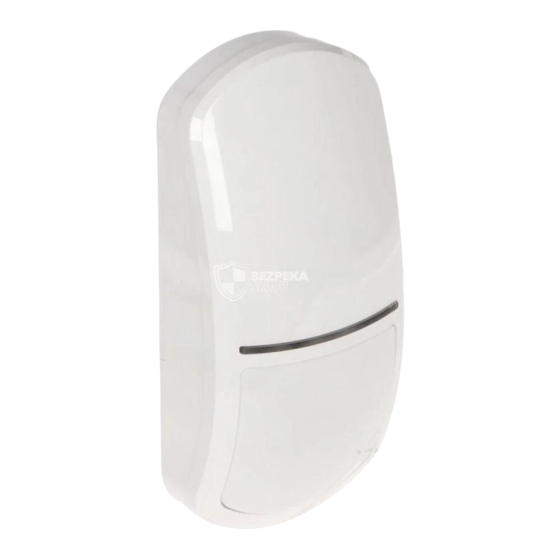
APD-200 SATEL The APD-200 detector is used to detect motion in a protected area. It is designed for operation within the ABAX 2 / ABAX two-way wireless system. This manual applies to the detector with firmware version 1.00 (or newer), which is supported by: ... - Page 5 SATEL APD-200 Temperature measurement accuracy ................±1°C Standby current consumption ................... 70 µA Maximum current consumption ..................12 mA Detectable speed ...................... 0.3...3 m/s Warm-up period ........................35 s Recommended installation height ................2 m...2.4 m Coverage area ....................15 m x 24 m, 90°...
-
Page 6: Installation
APD-200 SATEL Test mode The test mode makes the detector testing easier, because the LED indicators are enabled. How to start and end the test mode is described in the ABAX 2 / ABAX controller manual / the INTEGRA 128-WRL control panel manual. - Page 7 SATEL APD-200 Do not expose the battery to very low pressure due to the risk of battery explosion or leakage of flammable liquid or gas. Be particularly careful during installation and replacement of the battery. The manufacturer is not liable for the consequences of incorrect installation of the battery.
- Page 8 APD-200 SATEL 3. Install the battery and add the detector to the wireless system (see the ABAX 2 / ABAX controller manual or the INTEGRA 128-WRL control panel installer manual). The sticker with serial number which shall be entered when registering the detector in the system can be found on the electronics module.
- Page 9 SATEL APD-200 10. Secure the enclosure base to the wall (Fig. 4) or the bracket fastened with screws to the wall or ceiling (Fig. 5). The wall plugs (anchors) delivered with the device are intended for concrete, brick, etc. For other types of surface (drywall, styrofoam), use the appropriately selected wall plugs.
- Page 10 APD-200 SATEL 11. Fasten the electronics module in the enclosure. 12. If the detector is to protect the creep zone, the knob located on the inner side of the enclosure cover is to be set in position shown in Fig. 6-A. If the detector is NOT to protect the creep zone, set the knob to the position shown in Fig.
- Page 11 SATEL APD-200 15. Start the test mode (see the ABAX 2 / ABAX controller manual / the INTEGRA 128-WRL control panel manual).
- Page 12 You can change the detector enclosure cover to install another lens instead. The SATEL product range includes covers with the curtain (CT) lens as well as with the long-range (LR) lens.
Need help?
Do you have a question about the ABAX 2 APD-200 and is the answer not in the manual?
Questions and answers