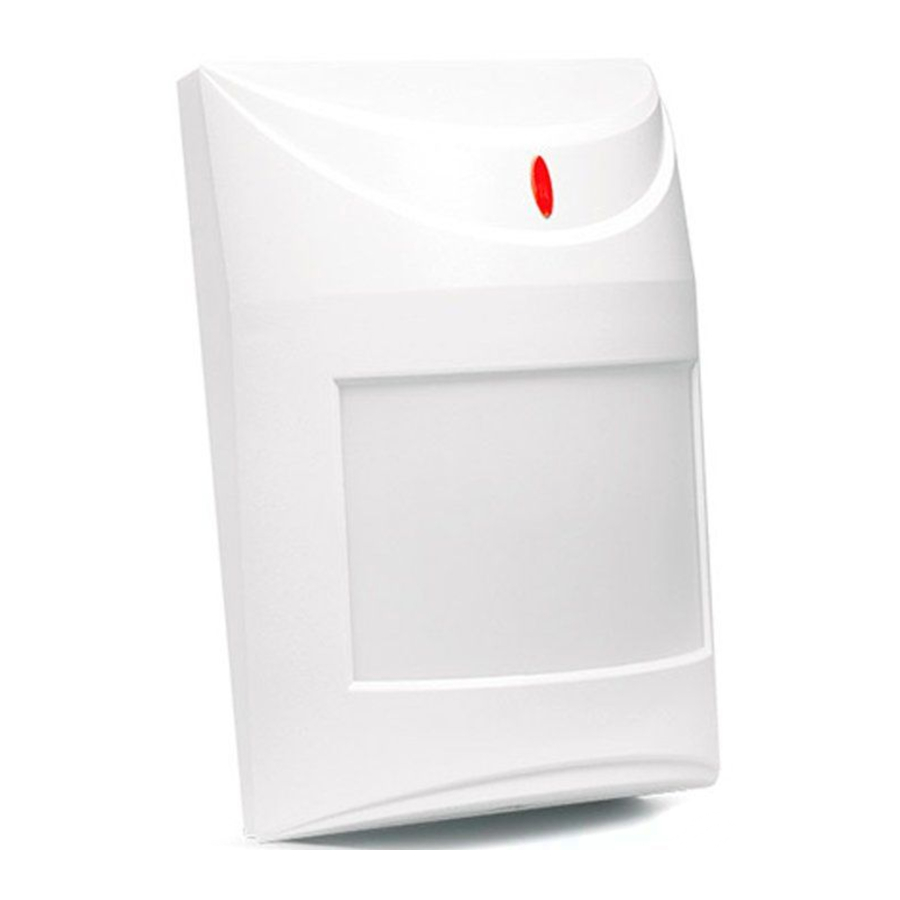
Satel AQUA Pet - infrared detector with pet immunity Manual
- Installation (2 pages)
Advertisement
The AQUA Pet detector allows detection of motion in the protected area. This manual applies to the detector with electronics version 2.4 (or newer) and firmware version 2.00 (or newer).
FEATURES
- Dual element pyrosensor.
- Digital motion detection algorithm.
- Pet immunity up to 15 kg.
- Digital temperature compensation.
- Selectable detection sensitivity.
- Built-in EOL resistors (Double EOL).
- LED alarm indicator.
- Pre-alarm feature.
- Supply voltage control.
- Tamper protection against cover removal.
DESCRIPTION
After motion is sensed by the detector in the coverage area, the alarm relay contacts will open for 2 seconds.
Supply voltage control
In the event of the voltage drop below 9 V (± 5%) for more than 2 seconds, the detector will signal a trouble. The trouble is indicated by the activation of alarm relay and the steady red light of LED indicator. The trouble signaling will continue as long as the trouble persists.
Electronics board

- terminals:
NC – alarm output (NC relay).
TMP – tamper output (NC).
COM – common ground.
12V – power input. -
red color LED to indicate:
- prealarm – short flash (approx. 120 ms);
- alarm – ON for 2 seconds;
- warm-up – blinking slowly;
- low supply voltage – ON.
- configuration pins for detector outputs:
- the built-in resistors are to be used – place the jumpers as shown in Fig. 2 (connect the outputs as shown in Fig. 7),
- the built-in resistors are not to be used – place the jumpers as shown in Fig. 3 (connect the outputs as shown in Fig. 8).
- dual element pyrosensor. Do not touch the pyroelectric sensor, so as not to soil it.

- tamper switch (NC).
- scale for positioning the electronics board.
- fixing screw hole.

- detector configuration pins:
PIR SENS. – selecting the PIR sensor sensitivity – see: Fig. 4 (A – low sensitivity, B and C – medium sensitivity, D – high sensitivity).
LED ON/OFF – enable/disable the LED indicator (jumper installed – LED enabled; jumper removed – LED disabled).
INSTALLATION
 Disconnect power before making any electrical connections.
- Remove the front cover (Fig. 5).
- Remove the electronics board.
- Make the openings for screws and cable in the enclosure base.
- Pass the cable through the prepared opening.
- Secure the enclosure base to the wall (Fig. 6).
- Fasten the electronics board. The middle line of the scale for positioning the electronics board should be aligned with the mark in the enclosure base (the detector installed at a height of 2.4 m above the floor).
- Connect the wires to the corresponding terminals.
- Using the jumpers, set the detector working parameters.
- Replace the cover.
START-UP AND WALK TEST
Note: When testing the detector, the LED should be enabled.
- Power-up the detector. The LED will start blinking, which indicates the detector warm-up.
- When the LED stops blinking, check that moving within the coverage area (Fig. 9 shows the maximum coverage area – at the maximum sensitivity) will activate the alarm relay and make the LED light up.

- If necessary, change the detector sensitivity (pins PIR SENS.).

In the event of the voltage drop below 9 V (± 5%) for more than 2 seconds, LED enabled; jumper removed – LED disabled). the detector will signal a trouble. The trouble is indicated by the activation of alarm relay and the steady red light of LED indicator. The trouble signaling will continue as long as the trouble persists.
SPECIFICATIONS
| Supply voltage | 12 V DC ±15% |
| Standby current consumption | 7.5 mA |
| Maximum current consumption | 8.5 mA |
| EOL resistors | 2 x 1.1 kΩ |
| Relay contacts rating (resistive load) | 40 mA / 16 V DC |
| Alarm signaling period | 2 s |
| Warm-up period | 45 s |
| Detectable speed | 0.3...3 m/s |
| Standards complied with | EN50130-5, EN50131-1, EN50131-2-2, EN50130-4 |
| Security grade according to EN50131-2-2 | Grade 2 |
| Environmental class according to EN50130-5 | II |
| Operating temperature range | -30...+55°C |
| Maximum humidity | 93±3% |
| Recommended installation height | 2.4 m |
| Dimensions | 63 x 96 x 49 mm |
| Weight | 75 g |
Documents / ResourcesDownload manual
Here you can download full pdf version of manual, it may contain additional safety instructions, warranty information, FCC rules, etc.
Download Satel AQUA Pet - infrared detector with pet immunity Manual
Advertisement


Need help?
Do you have a question about the AQUA Pet and is the answer not in the manual?
Questions and answers