Table of Contents
Advertisement
Quick Links
Preface
Notice for All Users
•
Consult the operation manual (this document) for proper use of your computer.
•
The product and the accessories are subject to change without prior notice.
•
SHARP assumes no responsibility for results arising from use of pre-installed and
third party software. Consult the software vendor for resolution of problems.
(Read the service condition of the software before use.)
•
SHARP assumes no responsibility for problems caused by incorrect handling,
repairs, defects, battery replacement or any other cause.
Operation Manual
i
Advertisement
Table of Contents

Related Manuals for Sharp Actius PC-MC22


Summary of Contents for Sharp Actius PC-MC22
- Page 1 The product and the accessories are subject to change without prior notice. • SHARP assumes no responsibility for results arising from use of pre-installed and third party software. Consult the software vendor for resolution of problems. (Read the service condition of the software before use.) •...
-
Page 2: Preface
A shielded I/F cable is required to insure compliance with FCC regulation for Class B computing equipment. ® * As an ENERGY STAR Partner, SHARP has determined that this product meets ® the ENERGY STAR guidelines for energy efficiency. Declaration of Conformity SHARP PERSONAL COMPUTER, PC-M4000 Series This device complies with part 15 of the FCC rules. -
Page 3: About The Modem
Operation Manual About the Modem This equipment complies with Part 68 of the FCC rules and the requirements adopted by the ACTA. On the bottom of this equipment is a label that contains, among other information, a product identifier in the format US:AAAEQ##TXXXX. If requested, this number must be provided to the telephone company. - Page 4 To program this information, refer to the manual of the communication software. Copyright It is the intent of Sharp that this product be used in full compliance with the copyright laws of the United States and that prior permission be obtained from copyright owners whenever necessary.
-
Page 5: Notice For Users In Canada
Notice for Users in Canada This class B digital apparatus complies with Canadian ICES-003. About the Wireless LAN Operation is subject to the following conditions: (1) this device may not cause harmful interference, and (2) this device must accept any interference received, including interference that may cause undesired operation. - Page 6 Preface TO PREVENT ELECTRICAL SHOCK, DISCONNECT THE AC CORD AND REMOVE THE BATTERY BEFORE SERVICING. CAUTION: FOR A COMPLETE ELECTRICAL DISCONNECTION, PULL OUT THE MAINS PLUG AND THE BATTERY. VORSICHT: UM DIE STROMZUFUHR VOLLSTÄNDIG ZU UNTERBRECHEN, DEN NETZSTECKER HERAUSZIEHEN UND DIE BATTERIE ÈNTFERNEN. ATTENTION: POUR UN ARRET TOTAL DU SYSTEME, DECONNECTEZ LA PRISE DE COURANT SECTEUR ET LA BATTERIE.
-
Page 7: Safety Precautions
Safety Precautions General • Follow all cautions and instructions marked on your computer. • Except as described elsewhere in this manual, refer all servicing to qualified personnel. Immediately shut off your computer and seek servicing under the following conditions. • The power cord or plug is damaged or frayed. - Page 8 Preface Usage • Never push any objects into the cabinet openings. They may touch the dangerous voltage points or short parts that could result in fire or electrical shock. • Do not press or place heavy objects on your computer. Strong pressure can damage the cabinet or make your computer fail.
- Page 9 Battery Pack Precautions CAUTION DANGER OF EXPLOSION IF BATTERY IS INCORRECTLY REPLACED. REPLACE ONLY WITH THE SAME OR EQUIVALENT TYPE RECOMMENDED BY THE MANUFACTURER. DISCARD USED BATTERIES ACCORDING TO THE INSTRUCTIONS. Handling • Do not put the battery pack in a fire. It could explode and cause injury. •...
- Page 10 Preface AC Power Precautions • Plug the AC power cord directly in a wall jack. Plugging too many leads into a single socket may result in fire. • Never plug in or remove the AC power cord or AC adapter with wet hands for prevention of electric shock.
- Page 11 • Do not use the telephones to report a gas leak in the vicinity of the leak. • Never use telephone jacks in wet locations unless they are specifically designed for wet locations. • Never touch uninsulated telephone wires or terminals while they are connected to a network interface.
- Page 12 Preface PC Disposal or Transfer Warning This product utilizes tin-lead solder, and a fluorescent lamp containing a small amount of mercury. Disposal of this product may be regulated due to environmental considerations. For disposal or recycling information, please contact your local authorities or the Electronics Industries Alliance: www.eiae.org.
- Page 13 Other Precautions • Periodic back-up copies of your important data should be made to protect your data in the event of hard disk failure or loss of the data on the hard disks. Use other storage devices for the backup. •...
-
Page 14: Notice Of Computer Security
Preface Notice of Computer Security The Windows operating system on this computer provides the Security Center, which manages the security features of your computer. It provides the status of the following security functions and enables you to change their settings: Firewall, Automatic Updates, and Virus Protection. -
Page 15: Notice Of Security With Wireless Devices
Security measures are important for all users to understand for the safe use of wireless LAN. SHARP encourages all users to configure the security settings with their own judgment and responsibility. -
Page 16: About This Manual
Information in this manual is subject to change without notice and does not represent a commitment on the part of SHARP Corporation and its sales subsidiaries. SHARP Corporation and its sales subsidiaries shall not be liable for technical or editorial errors or omissions contained herein; nor for incidental or consequential damages resulting from the furnishing, performance, or use of this material. -
Page 17: Recording Important Information
Recording Important Information For future reference, please record the following information in the spaces provided below. Model Number: Serial Number: Date of purchase: Dealer’s Name: Place of purchase: Password: The serial number is printed on a sticker located on the bottom of the computer. Operation Manual xvii... -
Page 18: Manual Conventions
Preface Manual Conventions This manual uses a set of style conventions described below. Notes and Cautions are italicized with icons: A note icon informs you of a special technique or information that may help you perform a task or better understand a process. A caution icon alerts you to something that may cause a problem or damage to hardware, software or data. -
Page 19: Table Of Contents
Table of Contents Table of Contents Preface Notice for All Users ...i Notice for Users in the USA ...ii Notice for Users in Canada ...v Safety Precautions...vii Notice of Computer Security ...xiv Notice of Security with Wireless Devices...xv About This Manual ...xvi Recording Important Information ...xvii Manual Conventions ...xviii Table of Contents...xix... - Page 20 Peripherals Peripheral Device Ports ...3-1 USB Devices ...3-3 Optional External Floppy Disk Drive Unit ...3-4 Printers ...3-7 External Monitors...3-8 Audio System ...3-11 PC Cards...3-14 Communication Functions Local Area Network (LAN)...4-1 Wireless LAN...4-7 Built-in Modem ...4-19 Network Setup Utility...4-23 Setup Utility Running the Setup Utility ...5-1 Main Menu ...5-3 Advanced Menu...5-4...
-
Page 21: Table Of Contents
Table of Contents Troubleshooting Common Problems... T-1 Trouble when Starting... T-2 Trouble with the Keyboard or Touchpad ... T-3 Trouble with the Display... T-4 Trouble with Floppy Disks... T-5 Trouble with the Optical Drive ... T-6 Trouble with the Hard Disk ... T-8 Trouble with Communications... -
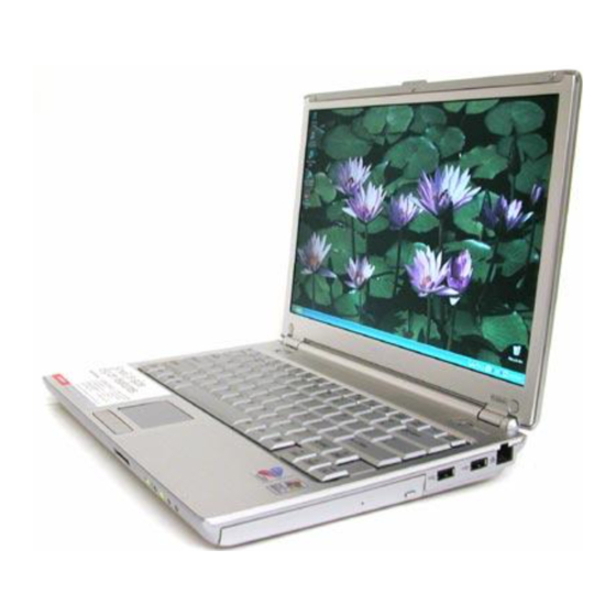
Page 22: Overview Of Computer
Overview of Computer Overview of Computer Each number after an arrow indicates the page referring to the part. Actual appearance of your computer may be slightly different depending on the model. Speakers Power Button → 1-3 Keyboard → 1-8 Touchpad →... - Page 23 Right Optical Drive → 1-9 Left AC Adapter Jack → 1-2 External Display Port → 3-8 Ventilation Openings→ vii Headphone/Audio Output Jack→ 3-11,12 LAN Jack → 4-2 USB Ports → 3-3,4,7 Security Slot→ A-5 PC Card Slot→ 3-14 Microphone Jack →...
- Page 24 Overview of Computer Rear Bottom Battery Pack→ 2-1 xxiv Modem Jack → 4-20 Ventilation Openings→ vii...
-
Page 25: Basic Operations
Basic Operations This chapter describes the basic operations of the computer. Properties Dialog Box on Windows In this manual, you will often see the expression “XXX Properties dialog box.” A dialog box is a window containing text boxes, check boxes, buttons, etc, with which you can send commands to Windows or other application programs. - Page 26 Basic Operations Plug the AC power cord into the AC adapter. Plug the AC adapter cable into the AC adapter jack on the computer. Plug the AC power cord into a wall outlet. AC Power Cord To Wall Outlet Steady the base cabinet of the computer with one hand and hold the jutted part with your thumb or finger of the other hand, and then raise the cover.
-
Page 27: Turning Off Your Computer
Press the power button to turn on the computer. Power Button Power Indicator When you turn on the computer, the power indicator ( the computer goes through a self test to detect any problems, and the Windows setup process starts. Do not touch or operate the keyboard and touchpad until Windows completely activates unless you are prompted to do so. -
Page 28: Choosing Power Source
Basic Operations • Do not turn off, reset or move the computer while the hard disk indicator, the optical drive indicator or the indicator on an optional external floppy disk drive unit is lit. Doing so may damage or even wipe out the data. -
Page 29: Using The Ac Adapter
Using the AC Adapter When connected to a wall outlet, the AC adapter provides power for operation and charges the battery. The AC input voltage can range from 100 to 240 volts so that you can use the computer with the appropriate plug adapter. The AC power cord included with the computer is appropriate for the voltage used in the area in which you purchased the computer. -
Page 30: Using The Touchpad
Basic Operations Using the Touchpad The computer is equipped with an integrated touchpad pointing device. Using the touchpad, you can move the pointer, select an item from a menu, and perform other tasks in the same way you would with a mouse. •... -
Page 31: Changing The Configuration
Click, Double-click, and Right-click To click or double-click, you can use the left button just like that of a mouse. Instead of clicking the left button, you can also just tap gently anywhere on the rectangular pad. For right-clicking, you must use the right button. If the interval between clicks is too long, the double-clicking will not work. -
Page 32: Using The Keyboard
Basic Operations Using the Keyboard The computer, equipped with the Windows Enhanced Keyboard, provides all the functionality of a full-sized desktop keyboard. Special Keys Windows Key Application Key System Function Keys The keyboard contains the function keys labeled F1 through F12 for special actions. Use them in conjunction with the Fn key. -
Page 33: Using The Optical Drive
(See the Power Saving section on page 2-7 for more information.) The APM button provides the same functions. If you press the APM button, the settings of the currently selected APM button mode will be applied. (For more information, refer to the Using the Advanced Power Management Button section on page 2-9.) Using the Optical Drive The computer is equipped with an optical drive allowing you to read from DVD and... - Page 34 The computer supports non-cartridge disks or Type2/Type4 removable cartridge disks. Before inserting a removable disk, remove the cartridge from the disk. • The Sharp Systems website at http://www.sharpsystems.com may provide a list of recommended media. • To play back the created disk, be sure to use a compatible computer or device.
- Page 35 Gently pull out the tray. Tray Do not touch the lens in the tray. If the lens becomes dirty, the drive may malfunction. Place your disk with label face up onto the tray and slightly press the center of the disk until it locks into place. Gently push the tray back into the computer.
-
Page 36: Removing Disks
Basic Operations Removing Disks Make sure the optical drive indicator is not lit and press the eject button. The optical drive tray will pop out. Make sure the optical drive indicator is not lit before pressing the eject button. Gently pull out the tray. Holding its edge, remove the disk from the tray. - Page 37 section on page 2-7.) • Close all unnecessary and automatic start-up applications. • Disable the screen saver. (Refer to the Wallpaper and Screen Saver section on page 1-20.) • Some disks restrict the writing or rewriting speed to ensure recording quality.
- Page 38 Basic Operations Changing the yRegion Code A DVD video has a region code which prevents playback of the disk in certain regions. The region code is labeled on the top of the disk. When shipped from the factory, your optical drive is set to a region code applicable to your area. Your optical drive region code can be changed.
- Page 39 The region code currently selected is marked in the left box. The region code of your DVD video is marked in the right box. If you want to change the drive code and play the DVD video, click OK. On some DVD videos, plural region codes are selectable in the right box of the Confirm Region dialog box.
-
Page 40: Using The Sd Card Slot
Basic Operations Using the SD Card Slot The computer is equipped with an SD card slot. You can insert/eject an SD memory card without turning off the computer. Before inserting an SD memory card into the slot, refer to its manual. •... - Page 41 Hold an SD memory card with the SD logo face up and the notched part toward the right and then insert it into the SD card slot. SD Card Slot SD Logo Face UP Notched Part Make sure to insert the card with the SD logo face up and the notched part toward the right.
-
Page 42: Controlling The Volume
Basic Operations Push the card into the computer and release it. The card will pop out slightly. SD Memory Card Gently pull out the card. Controlling the Volume You can adjust the output volume of the computer with the following volume controls that interact with each other. -
Page 43: Adjusting The Display
On Windows Click start - Control Panel. Click Sounds, Speech, and Audio Devices; then, Sounds and Audio Devices. If Classic view is selected, double-click the Sounds and Audio Devices icon. In the Sounds and Audio Devices Properties dialog box, slide the lever to control the output volume. - Page 44 Basic Operations Available Resolutions and Colors Resolution : 800 x 600, 1024 x 768, 1280 x 768, 1280 x 800 Number of Colors : 64K, 16M When displaying on your external display only, you can set any of the available resolutions for the external monitor.
-
Page 45: Sharing Your Computer
Sharing Your Computer If you are sharing the computer with your colleagues or family members, set a user account for each person. Every user can choose their favorite desktop setting, web site lists, or make their own My Documents folder etc., and save them to their user accounts. - Page 46 Basic Operations Select a new account to start Windows again. If you cannot see the Switch User in the Log Off Windows dialog box, click the Change the way users log on or off string in the User Accounts dialog box, and check Use Fast User Switching and click Apply Options. Setting the Password to User Account You can set a password to each user account to avoid unauthorized use of the computer.
- Page 47 Changing the Password Follow the steps 1-2 in the Setting Password section on the previous page. Select the account you want to change, if you log on to the computer as a member of the Computer administrators group. If you log on the computer with a limited account, go to the next step.
- Page 48 Basic Operations 1-24...
-
Page 49: Battery And Power Management
Battery and Power Management This chapter explains how to manage the computer’s power effectively and how to use the battery pack. In this section, you often see the expression “Power Options Properties dialog box.” To open the dialog box: Click start – Control Panel. Click Performance and Maintenance –... -
Page 50: Charging The Battery Pack
Battery and Power Management Charging the Battery Pack Connect the AC adapter to the computer and leave it until the battery is fully charged. To Wall Outlet When the battery indicator ( light turns green, the battery has been fully charged. •... -
Page 51: Low Battery Indication
• The remaining operating time depends on the amount of the power the computer is consuming. If you are using the audio system, PC card slot, SD card slot, hard disk drive, or peripheral devices with the computer, it will consume more battery power. •... -
Page 52: Conditioning The Battery Pack
Battery and Power Management In the Power Options Properties dialog box, select the Alarms tab. Set the battery level at which the alarms are activated. The recommended values of the Critical battery alarm are 5% or more and the Low battery alarm more than the value of the Critical battery alarm. -
Page 53: Changing The Battery Pack
Changing the Battery Pack Repeated use of the battery pack gradually decreases its capacity and its deterioration rate depends on the operating environment. If the battery life becomes extremely short even after conditioning the battery pack, you should buy a new battery pack. Consult your local dealer for a new battery pack. - Page 54 Battery and Power Management Align the projecting parts of the new battery pack to the notched parts of the computer. Be sure to completely match the projecting parts of the battery pack with the notched parts of the computer. Otherwise, the battery pack may drop out of the socket, and damage itself or cause injury.
-
Page 55: Power Saving
Confim that the spring release battery lever is in the locked position ( ) and then slide the battery lever back to the locked position ( ). Spring Release Battery Lever Power Saving The computer is equipped with Advanced Power Management software that is activated by the APM button. - Page 56 Battery and Power Management About the APM Button Modes • Max Power mode: Provides maximum system and subsystem performance. • Mobile mode: Provides controlled CPU performance and screen brightness. • Max Mobile mode: Provides more controlled CPU performance and most components are in low power mode.
- Page 57 resuming from a standby or hibernation mode. • Save your data before the computer enters a standby mode. If the power supply to the computer is stopped, the RAM contents will be lost. Select your user account if Windows requires when the computer resumes from the standby or hibernation mode.
- Page 58 Battery and Power Management • Controlled CPU performance levels (that are other than 100%) may cause some applications such as DVD playback to perform improperly. Change the CPU performance level back to 100%. • When you press the APM button, the current setting levels of the selected mode is applied.
- Page 59 The setting levels of each mode can be separately determined from the provided lists. To change the values, follow theses steps. Click start – All Programs – SHARP Advanced Power Management Utility – Advanced Power Management Button Settings. • The APM button settings window will appear.
- Page 60 Battery and Power Management Available APM Button Setting Levels CPU performance Four options are provided: 100%, 75%, 50%, and 25%. Brightness Thirteen options are provided: 100%, 92%, 85%, 76%, 69%, 62%, 54%, 46%, 38%, 31%, 23%, 15%, and 8%. Wireless LAN Do nothing Optical drive Do nothing...
- Page 61 Wireless LAN is set to OFF will stop the current reading/writing process or communication. • To reset to the default setting values of the APM button, click start – All Programs – SHARP Advanced Power Management Utility – Reset to default. Disabling System Standby/Hibernate...
- Page 62 Battery and Power Management Entering a Standby/Hibernation Mode Immediately You can allow the computer to enter a system standby or system hibernation mode in each of the following cases: • You select Stand By or Hibernate (which will replace Stand By if you press Shift key) in the Turn off computer dialog box.
- Page 63 If Ask me what to do is selected in the step 2 of You press the power button or You press Fn+F12 ( appear when you press the power button or the Fn+F12 ( combination. You can select System standby or System hibernate at that timing.
- Page 64 Battery and Power Management Reconnecting the Optical Drive To power on the optical drive and resume the connection, use one of the following instructions. It will take some time for the optical drive to be recognized by the computer after you complete one of the following: •...
-
Page 65: Peripheral Device Ports
Peripherals This chapter describes how to use peripheral devices with the computer. You can connect an optional floppy disk drive unit, a printer, an external monitor, a PC card, or other devices to the computer. To ensure the proper use, be sure to read the instructions for each peripheral device before connecting it to the computer. - Page 66 Peripherals Connection Ports for Peripherals Headphone /Audio Output Jack Microphone Jack External Display Port Port Design Port name USB Port External Display Port Headphone / Audio Output Jack Microphone Jack USB Ports Port Design...
-
Page 67: Usb Devices
USB Devices The computer has an interface called Universal Serial Bus (USB). Its two USB ports support USB1.1 and USB2.0. With a USB connection, you can connect/disconnect peripherals without turning off the computer. Generally, when you connect a device to the computer, the necessary driver will be installed automatically. -
Page 68: Optional External Floppy Disk Drive Unit
Optional External Floppy Disk Drive Unit You can use high-density (2HD) 1.44MB or double-density (2DD) 720KB floppy disks with the optional SHARP external floppy disk drive unit (CE-FD05). • 1.44MB (2HD) disks are appropriate for the drive unit. • There are some restrictions in using 720KB (2DD) disks. Refer to the Trouble with Floppy Disks section on page T-5. - Page 69 Handling the Floppy Disk • Do not open the shutter and touch the disk inside; otherwise, you will not be able to read or write data to the disk. • Do not place floppy disks near magnets or heat source, in direct sunlight or in a dusty place, etc.
- Page 70 Peripherals Ejecting the Floppy Disk Before ejecting the floppy disk, make sure the indicator of the floppy disk drive unit is not lit. Press the eject button firmly so that the disk pops out slightly. Eject and store the disk properly. Removing Optional External Floppy Disk Drive Unit To remove the unit, follow these instructions.
-
Page 71: Printers
Printers You can use a USB printer by connecting it to one of the USB ports on the computer. Before using a printer, read the printer manual and install the printer driver to the computer. Connecting the Printer When connecting the cable to one of the USB ports, be sure to keep the USB mark ( ) side up. -
Page 72: External Monitors
Peripherals External Monitors You can connect an external monitor to the computer to display images on it. • Some external monitors, which are not compatible with the computer, may not display correctly. • In this section, you often see the expression “Display Properties dialog box.”... - Page 73 Switching the Display You can switch the output display by the Fn+F5 ( performance on Windows. • When displaying on both the LCD monitor and an external monitor simultaneously, the external monitor must be capable of a 1280 x 800 resolution.
- Page 74 Peripherals Switching the Display on Windows Click the Display Properties icon ( If you cannot find the icon, click Point to Graphics Options and Output To. Select your favorite output display. Refer to the following to select the appropriate output display. LCD display only: select “Notebook.”...
-
Page 75: Audio System
Click OK. Click OK in the Confirm the Desktop Changes dialog box. Disconnecting the External Monitor Turn off the computer and the external monitor. Remove the display cable from the computer. Audio System You can output sound to speakers, audio equipment, or a headphone and also input it through a microphone. - Page 76 Peripherals Connecting Audio Equipment You can connect analog audio equipment to the audio output jack on the computer. Headphone/Audio Output Jack Stereo Mini Plug You can adjust the output volume on Windows by clicking the speaker symbol on the taskbar or use the Fn+F3 ( Connecting the Headphone Use a headphone with an impedance of 8 Ω...
- Page 77 Connecting the Microphone You can input sound using an external microphone connected to the microphone jack. Use an electric condenser microphone with an impedance of 1.5k Ω through 2.4k Ω and an allowable voltage of 2.5 V. Microphone Jack To input sound, Click start –...
-
Page 78: Pc Cards
Peripherals PC Cards The computer is equipped with a PC card (supporting PC Card Standard, CardBus compliant) slot, which can accommodate a Type II card. You can insert/eject the card without turning off the computer. Before inserting a PC card into the slot, refer to its manual. - Page 79 Insert a PC card into the slot with the label face up until it locks into place. Label Face Up If the dialog box asking you What do you want Windows to do? appears, select the task you want. Ejecting the PC Card •...
- Page 80 Peripherals Push the PC card eject button so that it will pop out from the side of the computer. PC Card Eject Button Push the PC card eject button until the inserted PC card pops out; then, remove it. Push the PC card eject button all the way inside the cabinet for safekeeping. 3-16...
-
Page 81: Communication Functions
Communication Functions This chapter explains how to use the LAN, wireless LAN, and built-in modem functions. • When you use communication software: • Connect the computer to the AC power source. • Do not allow the computer enter a system standby or system hibernation mode. - Page 82 Communication Functions Connecting Your Computer to the LAN Turn off the computer. Connect a LAN cable to the LAN jack and the network hub. LAN Jack Do not insert a modem cable into the LAN jack. It may damage the modem cable and the LAN jack.
- Page 83 Configuring the LAN Click start - Control Panel. Click Network and Internet Connections; then, Network Connections. If the Classic view is selected, double-click the Network Connections icon. Right-click Local Area Connection. From the pop-up menu, click Properties. In the Local Area Connection Properties dialog box, set the network setting according to the instruction of your network administrator.
- Page 84 Communication Functions Configuring Network Settings of the Computer • Before configuring the network settings, be sure to connect the two computers with a cross LAN cable and turn them on. • You need to perform the following process on the both computers. Click start –...
- Page 85 The Computer name should be unique. Type a name that is different from that of the other computer. 10. Type a Workgroup name and click Next. The Workgroup name should be same as that of the other computer. 11. Select Turn on file and printer sharing and then, click Next. 12.
- Page 86 Communication Functions Sharing Files and Folders This section provides how to share a folder on the network. With these steps you can also share a drive. Right-click on a folder to be shared and click Sharing and Security…. The XXX Properties dialog box will open.
-
Page 87: Wireless Lan
Copying Shared Files Click start – Control Panel. Click Network and Internet Connections; then, Network Connections. If the Classic view is selected, double-click the Network Connections icon. Click My Network Places in the Other Places field located on the left. Click View workgroup computers in the Network Tasks field. - Page 88 Communication Functions Wireless LAN Modes There are two kinds of wireless LAN modes: Infrastructure mode and Ad Hoc mode. Access Point (Infrastructure) Mode Infrastructure mode refers to a wireless network in which wireless devices communicate with each other through an access point (AP). Wireless devices can communicate with each other or can communicate with a wired network through AP.
- Page 89 See the Notice of Security with Wireless Devices section on page xv. Authentication The following may help you to protect your important data from illegal access. • SSID (Service Set Identifier) “SSID” is a common network name. An SSID acts as a password that is shared with all connecting wireless devices, resulting in preventing access by any device that does not have the SSID.
- Page 90 Communication Functions Encryption The computer provides the following encryption mechanisms including: TKIP, AES, and WEP. The three techniques allow you to encrypt data to be transmitted, which will make illegal interception more difficult. • To use the WEP functions, your communication partner must support the functions.
- Page 91 Activating the Wireless LAN Antenna To communicate using the wireless LAN, the integrated antenna must be activated. You can enable/disable the antenna by pressing the Fn+F1 ( When the antenna indicator ( indicator light is off, it is disabled. Wireless LAN Antenna Indicator Disable the antenna on airplanes and in specific places where radio- susceptible equipment is nearby such as medical and electrical...
- Page 92 Communication Functions Configuring the Wireless LAN Setting The following steps lead you to configure the wireless LAN setting by automatically obtaining the IP address, DNS server, etc. from an access point. By default, no configuration is needed. Skip these steps and go to the Connecting to Network section on the next page.
- Page 93 Connecting to a Network This section describes how to connect to a WEP enabled access point or WPA- PSK/TKIP capable access point. (WPA-PSK/TKIP refers to WPA with pre-shared key (PSK) with Temporal Key Integrity Protocol (TKIP) encryption.) For access points with user authentication, consult your network administrator.
- Page 94 Communication Functions • When the computer successfully connects to the selected access point, the Connected signage will appear in the connected network name field and the Wireless Network Connection icon ( will change to ( • Entering an incorrect network key or selecting an inappropriate key index will show the Limited or no connectivity signage in the network name field and the icon on the taskbar will change to ( the correct network key and/or change the key index referring to the...
- Page 95 Communicating with Other Computers This section describes how to communicate between wireless computers with built-in wireless LAN or a wireless LAN card installed. To enable wireless communication between the computers; • Assign IP address and subnet mask for each computer. •...
- Page 96 Communication Functions Confirm the computer and other computers are assigned the same Network name. 12. Confirm Open is selected in the Network Authentication pull-down menu and WEP in the Data encryption pull-down menu. 13. Clear the box of The key is provided for me automatically. 14.
- Page 97 Changing the Security Mode This section describes how to change the security mode to WEP or WPA-PSK with TKIP or AES. When using the user authentication security technology, consult your network administrator for the mode changes. Right-click the Wireless Network Connection icon ( taskbar.
- Page 98 Communication Functions If necessary, change the key index in the key index fields. • The key index options of the computer are 1 through 4. • Some access points and computers have the options 0 through 3. Refer to the table below for matching. Access Point 1 /Computer 1 (ex.
-
Page 99: Built-In Modem
Built-in Modem You can use the built-in modem for data transfer and fax communication. • The built-in modem on the computer is designed only for regular analog telephone lines. The modem may be damaged when connected to a digital ISDN terminal or a digital PBX. •... -
Page 100: Configuring The Modem
Communication Functions Connect a modem cable to the modem jack and the telephone line. To Telephone Line Be sure not to insert a modem cable into the LAN jack on the rear side of the computer. It may damage the LAN jack and the modem cable. Connect the modem to the telephone line directly. -
Page 101: Removing The Modem Cable
After the configuration, click or double-click the Phone and Modem Options (icon) to open the Phone and Modem Options dialog box and double-click the location name in the Locations field of the Dialing Rules tab for the information you set above. Clicking Edit…... - Page 102 Communication Functions Press and hold the connector tab of the modem cable and then, pull out the cable. Connector Tab 4-22...
-
Page 103: Network Setup Utility
Network Setup Utility With the Network Setup Utility, you can define specific network settings based on your network environments such as work, home, etc. You can also allow for the computer automatically to switch to the appropriate network. • Not every setting item can be stored. •... - Page 104 Communication Functions In the Register an icon and network name dialog box, select the SHARP icon or Windows icon, then, click the Select icon button. Select an icon and click OK. Type a network name, then, click OK. The selected icon appears on the main screen of the Network Setup Utility window.
-
Page 105: Setup Utility
Setup Utility This chapter describes how to run the Setup Utility to change settings on the computer. Running the Setup Utility With the Setup Utility, you can customize the system configuration information, such as time and date, or passwords. The information you have specified is saved in a special area called CMOS RAM, which the system reads every time you turn on the computer. - Page 106 Setup Utility Entering and Exiting the Setup Utility Turn on the computer. When Press F2 for System Utilities appears, press F2. Change to the desired settings. (Refer to the next section.) Select Exit menu; then, press Enter. Select one of the exit methods, and press Enter. Confirm the message and press Enter again.
-
Page 107: Main Menu
Internal NumLock defines whether the numlock keys of the built-in keyboard are always enabled or disabled. Quiet Boot defines whether SHARP logo appears on the screen while booting. CPU Information shows the information of the CPU. System Memory shows the volume of the conventional memory. -
Page 108: Advanced Menu
Setup Utility Advanced Menu Resolution Expansion defines whether the screen is expanded when it is in a low resolution. (The setting is not used on Windows.) Plug&Play O/S normally has to be set to default as “Yes.” Max ACPI C-State determines the amount of power management while the system is idling. -
Page 109: Setting The Password
Passwords Setting a password will protect the computer against unauthorized access. Once a password is set, the system requires the password when entering to the Setup Utility. If the Password on boot is enabled, the system will require the created password when the computer is turned on. -
Page 110: Changing The Password
Setup Utility Select Exit menu and confirm Exit Saving Changes is highlighted; then press Enter. Confirm Yes is highlighted and press Enter. The system restarts. • To enable the supervisor password or the user password when booting up the computer, enable the Password On Boot. •... -
Page 111: Boot Menu
Boot Menu Boot Sequence specifies where the system boots from. Press Enter to open the sub menu. The system boots from the drive at the top of the list. If the system cannot find the drive, it will boot from the second one; then, third one; then forth one. Use arrow keys to select the drive you want to move and then, use the space bar or minus key to move it up or down. - Page 112 Setup Utility...
-
Page 113: Appendixes
Appendixes The appendixes contain additional information on the use and care of the computer. Memory Module You can upgrade the memory amount of the computer by installing an expansion memory module. See the specification on the separate specification sheet for the default and maximum memory size. - Page 114 Appendixes Loosen the screw and remove the cover. Cover Turn over the sheet. Align the notched part of a memory module to the projecting part of the memory socket and then, put the module into the socket until it is seated. Projecting Part Screw Sheet...
- Page 115 Gently press the module to place it into the socket, matching the notched parts of the module with the projecting parts of the socket. Projecting Parts Match the tabs of the cover with the notched parts of the computer, and then, put down the cover so that it is placed in the original position.
-
Page 116: Removing The Memory Module
Appendixes Finding the Memory Size Turn on the computer. When the message Press F2 for System Utilities appears, press F2 to open the Setup Utility. Find the memory size shown in the Extended Memory field in the Main menu. • The available memory size will appear, minus the total amount of shared video memory size and other factors. -
Page 117: Maintenance And Care
Maintenance and Care This section provides you with information on how to maintain your computer in excellent working condition. Using a Security Cable You can connect a security cable to the security slot on the computer to prevent theft. Security Slot Security Cable Cleaning the Computer Cabinet... - Page 118 Appendixes Screen The surface of the screen may become smeared and accumulate dust during use. Avoid touching the screen with your fingers when using the system. Gently wipe the surface of the screen with a soft cloth that has been dipped in a mild detergent solution and squeezed dry.
-
Page 119: Virus Protection
Virus Protection Computer viruses are referred to as a kind of malignant program intentionally engineered. When the computer is infected, several damages would be generated; data in the hard disk may be destructed; the computer may be provided external operation by unauthorized users;... - Page 120 Appendixes automatically detect the important programs to be updated and install them if any. Click start – Control Panel – Security Center. In the Security Center window, click the Turn on Automatic Updates button. Close the window. Updating Windows You can update Windows by clicking the Windows Update icon on the taskbar or accessing to the Microsoft site.
- Page 121 Follow the on-screen instructions to complete the Norton Antivirus wizard and the LiveUpdate. Running LiveUpdate Automatically The Automatic LiveUpdate function automatically updates the definition file. Be sure to complete the Norton AntiVirus wizard before going on these steps. Click start – All Programs – Norton AntiVirus – Norton AntiVirus 2005. Click Automatic LiveUpdate in the Subscription Service field.
-
Page 122: Data Execution Prevention
Appendixes Data Execution Prevention The computer is mounted with the CPU supporting Data Execution Prevention (DEP) technology (or a memory protection feature) built into the Windows operating system. With the DEP technology, the operating system marks some memory regions as non- executable and prevents execution of malicious program code there, which will result in protecting the computer from virus infection. - Page 123 Open the Security Center and confirm all of the Firewall, Automatic Updates and Virus Protection are ON. • Be sure to enable all of these three functions. • For details on the Security Center, refer to the Notice of Computer Security on page xiv.
-
Page 124: Data Backup And Restore
Appendixes Data Backup and Restore Your important data such as e-mails or files is stored on the hard disk of the computer. Backing up the data in another place is one of the ways that can protect your data against any disaster, data corruption or data erase, for example. Backing Up Data and Settings Backing Up Data You can back up your data on the D drive, external hard disk, or CD-R/RW disks. -
Page 125: Re-Installation Instructions
Re-installation Instructions Refer to this section to re-install the system of the computer. • The reinstallation process will overwrite all information in the C and D drives of the hard disk and restore the hard disk drive to its factory configuration. - Page 126 Appendixes 2. GRANT OF LICENSE. The Software is being licensed to you, which means you have the right to use the Software only in accordance with this License Agreement. The Software contains pre-installed software for disaster recovery purposes. The Software is only authorized for distribution together with a specific computer.
-
Page 127: Recovery Options
8. NO WAIVER. Any failure by either party to this agreement to enforce a specific part of the agreement in a specific situation is not a waiver of rights under the agreement. The party may still enforce the rest of the agreement in that situation and may still enforce some or all of the agreement in other situations. -
Page 128: Backing Up Data
Appendixes Backing Up Data Before you format the hard disk, back up your data. For details on how to back up your data, refer to Data Backup and Restore section on page A-12. Selecting Way to Recover Your System The computer has partitioned the hard disk into two drives (C: and D:) when it was shipped from the factory. - Page 129 Formatting Drives and Re-installing Windows The formatting and re-installing process will restore the hard disk drive to its factory configuration. To ensure the computer’s safety, enable the virus protection/cleaner software and update the virus definition file to the latest one. Also, the Windows Update should be run for virus prevention.
- Page 130 Appendixes Select the volume of C drive and press Enter. 10. Read the message and select Continue; then, press Enter. The formatting and re- installation will start. Although the pointer may be shown on the screen, never touch the keyboard or the mouse during recovery except when the message prompts you to.
- Page 131 Intended Purpose: The SOFTWARE PRODUCT is installed on and shipped with a computer manufactured by Sharp. You may use the SOFTWARE PRODUCT only for making a Bootable CD from the recovery image file that is pre-installed on the hard disk.
- Page 132 Limitation of Liability: In no event shall ECI or Sharp be liable for any special, incidental, indirect, or consequential damages, or for damages for loss of business profits, business interruption, loss of business information, or other pecuniary loss, even if ECI or Sharp has been advised of the possibility of such damages.
- Page 133 The icon ( ) will change to ( Creating Recovery CDs Connect the AC adapter to the computer. Be sure to connect the AC adapter. If the battery is completely discharged, the burning CD process will be stopped. Insert a blank CD-R into the optical drive. If a dialog box or window appears, close it.
- Page 134 Appendixes • Store the burned disks in a secure place. • Keep your disks away from direct sunlight, heat and excessive moisture. Close the optical drive. 10. Restart the computer. Enabling Auto Protect of Norton AntiVirus If the Norton Antivirus icon on the taskbar is disabled, appearing as ( steps.
- Page 135 Insert the Recovery CD disk 1 into the optical drive. In the Exit menu, select Load Setup Defaults; then, press Enter twice. In the Boot menu, confirm the Boot Sequence is highlighted and then, press Enter. In the Boot Sequence, select the Optical Disk Drive and press the space bar to place the Optical Disk Drive in the top of the list;...
- Page 136 Appendixes A-24...
-
Page 137: Troubleshooting
If you still have a problem after trying all the suggested remedies in this chapter, contact your dealer or, for users in U.S, call: 1-800-BE-SHARP (237-4277). The problems that you might encounter can be divided into two basic categories: hardware and software. -
Page 138: Trouble When Starting
Troubleshooting Trouble when Starting Why doesn't the power indicator or the battery indicator turn on? • Make sure the AC adapter is correctly connected to the AC adapter jack of your computer. • Make sure the AC power cable is correctly connected to a live wall outlet. To find it is live or not, connect another electric equipment to the wall outlet. -
Page 139: Trouble With The Keyboard Or Touchpad
12. Make an appropriate setting on the Setup Utility, if necessary. If you want to keep the default settings, no setting performance is needed. • If the operation above fails to work, contact your dealer or call: 1-800-BE-SHARP (237-4277) for users in U.S. Trouble with the Keyboard or Touchpad Why doesn't the keyboard or the touchpad respond to your operation? •... -
Page 140: Trouble With The Display
Troubleshooting Why doesn't the touchpad function? • The surface of the touchpad or your palm may be moist or dirty and grease. Wipe the touchpad with a soft, dry cloth. • The touchpad may be disabled because of the connected USB mouse. Remove the mouse or enable the touchpad by following these instructions. -
Page 141: Trouble With Floppy Disks
Why does the external monitor display nothing or distorted images? • Confirm the monitor is turned on. • Confirm the monitor is connected correctly. • Make sure the external monitor is selected as the output display by pressing Fn+F5 ( ). •... -
Page 142: Trouble With The Optical Drive
Troubleshooting • The floppy disk may not be formatted or could be corrupted. Format the disk or use another disk. • If you cannot write to a floppy disk, the disk may be write-protected. Eject the disk and ensure that the write-protect tab covers the detection hole. •... - Page 143 Why can’t I write/delete the data onto/from a disk? • Confirm the disk is available in writing or deleting data. • If you wish to use the Windows CD writing software, you may need to enable it. (Refer to Windows Help and Support.) Why doesn’t the DVD video play smoothly? •...
-
Page 144: Trouble With The Hard Disk
Troubleshooting • If you press the APM button and select the mode where the Optical drive is OFF, the optical drive powers off. To power it on, press the optical drive eject button or Fn+F2 keys. Trouble with the Hard Disk Why can't I read or write data to/from the hard disk? •... - Page 145 • Close the applications currently opened. • Try to connect another ISP (Internet Service Provider), or try to connect in some other time. Why can't I access the LAN? • Confirm the cable is properly connected to the LAN jack and the network hub. •...
- Page 146 Troubleshooting Select the desired network in the Available wireless networks list; then, connect to the network. (Refer to the Confirming the Status of Wireless Connection section on page 4-14.) • Repair the connection with the following steps. Right-click the Wireless Network Connection icon. Click Repair.
-
Page 147: Trouble With Peripherals
• Confirm the WEP keys are correctly set to your computer if the WEP security of the communicated computers is enabled. How can I detect the MAC address? • Follow the instructions below: Click start – All Programs – Accessories – Command Prompt. Type ipconfig/all;... -
Page 148: Trouble With Security Settings
Troubleshooting • Disable System standby and System hibernates. If this does not work, set Turn off hard disks to Never. Trouble with Security Settings Why do I have the message “Your computer might be at risk” each time I boot my computer? •... - Page 149 Why do I get the message This site might require the following ActiveX control in the information bar? • The Microsoft Internet Explorer prevents active contents from appearing. The following steps allow them to appear. Before performing the steps, ensure the safety of the contents.
- Page 150 Troubleshooting Click the Hardware tab; then, Device Manager. Double-click the device you cannot use and confirm Use this device (enable) appears in the Device usage field. Why can't I produce sound? • Click or double-click the speaker symbol on the taskbar and check the Windows volume.
- Page 151 Why can’t I find the system drivers and software applications? • You may accidentally remove them. Refer to the following to retrieve them. • The drivers are stored on the last recovery disk if you have created the recovery CDs. •...
- Page 152 Troubleshooting T-16...
-
Page 153: Index
Index AC adapter connecting, 1-1 using, 1-5 Account creating, 1-21 switching, 1-21 APM button about, 2-8 using, 2-9 Audio controlling output volume, 1-18 Backing up data, A-12 Battery pack changing, 2-5 charging, 2-2 checking level, 2-2 conditioning, 2-4 indicator, 1-4, 2-2,3 low battery indication, 2-3 Cleaning computer, A-5... - Page 154 Index File sharing copying, 4-7 sharing, 4-6 Floppy disk ejecting, 3-6 handling, 3-5 inserting, 3-5 troubleshooting, T-5 Floppy disk drive (external) connecting, 3-4 removing, 3-6 Hard disk drive troubleshooting, T-8 Indicators battery, 1-4, 2-2,3 optical drive, 1-10 power, 1-3,4 status, xxii wireless LAN antenna, 4-11 Keyboard application key, 1-8...
- Page 155 Power choosing AC or battery, 1-4 indicator, 1-3,4 Power saving APM button, 2-9 system hibernate, 2-8 system standby, 2-8 Printers, 3-7 Re-installation about, A-13 CD recovery, A-18, 22 creating recovery CDs, A-21 hard disk recovery, A-17 preparing, A-15 selecting way, A-16 Restoring data and settings, A-12 Screen Saver, 1-20 SD card...
- Page 156 Index confirming the status, 4-14 connecting to a network, 4-13 security measures, 4-8 security modes, 4-17 security notice, xv troubleshooting, T-9 wireless LAN modes, 4-8 Workgroup name, 4-5 Index-4...