Table of Contents
Advertisement
Quick Links
Advertisement
Table of Contents

Related Manuals for EK-Quantum Vector RX 6700XT Backplate


Summary of Contents for EK-Quantum Vector RX 6700XT Backplate
- Page 1 EK-Quantum Vector RX 6700XT Backplate BACKPLATE USER GUIDE...
- Page 2 This product is intended for installation by expert users only. Please consult with a qualified technician. Improper installation may result in damage to your equipment. EK assumes no liability whatsoever, expressed or implied, for the use of this product or its installation. The following instructions are subject to change without notice.
-
Page 3: Table Of Contents
TABLE OF CONTENTS BOX CONTENTS BACKPLATE DIMENSIONS REQUIRED TOOLS INSTALLING THE BACKPLATE PREPARING THE GRAPHICS CARD CUTTING AND PLACING THERMAL PADS ATTACHING THE BACKPLATE TESTING THE LOOP WARRANTY SUPPORT AND SERVICE SOCIAL MEDIA - 3 -... -
Page 4: Box Contents
EAN:103301 M2.5 x 8 AX1 Screw - Black (8 pcs) M2.5 x 8 AX1 Screw - Nickel (8 pcs) EK-Quantum Vector RX 6700XT Backplate Thermal PAD G 1.0mm - (120x24mm) (2 pc) Thermal PAD G 1.5mm - (120x24mm) (2 pcs) -
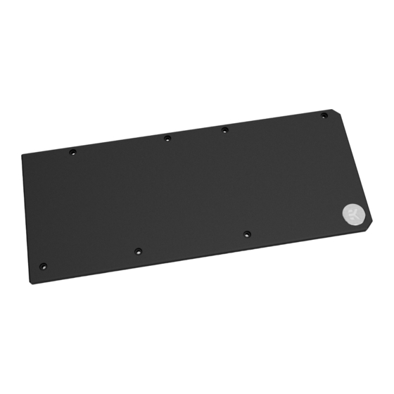
Page 5: Backplate Dimensions
BACKPLATE DIMENSIONS 249.6 mm REQUIRED TOOLS Phillips Head Screwdriver Scissors - 5 -... -
Page 6: Installing The Backplate
INSTALLING THE BACKPLATE STEP 1 PREPARING THE GRAPHICS CARD First, complete the installation of your EK-Quantum Vector RX 6700XT water block according to its installation manual. In case the water block is already installed, remove the seven (7) AX1 screws and their PVC washers, as shown in the image. -
Page 7: Attaching The Backplate
STEP 3 Once cut to size thermal pads should be applied to the backplate as shown in the image. G1.0 G1.5 G1.0 G1.0 G1.5 Thermal Pad G 1.0 mm G1.0 STEP 3 Thermal Pad G 1.5 mm G1.5 STEP 4 7x M2.5 x 8 AX1 Screw ATTACHING THE BACKPLATE Place the backplate on the PCB and make sure all holes are aligned. -
Page 8: Testing The Loop
TESTING THE LOOP To ensure the installation of EK components was successful, we recommend you perform a 24-hour leak test. When your loop is complete and filled with coolant, connect the pump to a PSU outside your system. Do not connect power to any of the other components. -
Page 9: Support And Service
SUPPORT AND SERVICE In case you need assistance or wish to order spare parts or a new mounting mechanism, please contact: https://www.ekwb.com/customer-support/ For spare parts orders, refer to the page with “BOX CONTENTS” where you can find the EAN number of each part you might need. Include the EAN number with quantity in your request.
Need help?
Do you have a question about the Vector RX 6700XT Backplate and is the answer not in the manual?
Questions and answers