Table of Contents
Advertisement
Quick Links
Advertisement
Table of Contents

Related Manuals for EK-Quantum Vector Master RX 6800/6900 D-RGB


Summary of Contents for EK-Quantum Vector Master RX 6800/6900 D-RGB
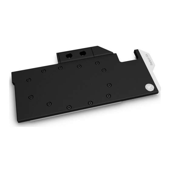
- Page 1 EK-Quantum Vector Master RX 6800/6900 D-RGB GPU WATER BLOCK USER GUIDE...
- Page 2 Before you start using this product, please follow these basic guidelines: Carefully read the manual before beginning with the installation process. Remove your graphics card from the computer for the safest mounting process to prevent any possible damage to your GPU or its circuit board (PCB).
-
Page 3: Table Of Contents
TABLE OF CONTENTS BOX CONTENTS WATER BLOCK DIMENSIONS TECHNICAL SPECIFICATIONS AND WATER BLOCK PARTS PREPARING YOUR GRAPHICS CARD REMOVING THE STOCK COOLER CLEANING THE PCB CUTTING AND PLACING THERMAL PADS APPLYING THERMAL COMPOUND INSTALLING THE WATER BLOCK PLACING THE BLOCK ON THE GRAPHICS CARD ATTACHING THE BLOCK TO THE GRAPHICS CARD INSERTING THE GRAPHICS CARD INTO THE CHASSIS FITTINGS AND TUBING... -
Page 4: Box Contents
Universal Mounting Mechanism – You may not need every screw from this package. EAN: 3831109872215 M2.5x4 AX1 Screw (16 pcs) M2.5x6 AX1 Screw (13 pcs) EK-Quantum Vector Master RX 6800/6900 D-RGB M2.5x8 AX1 Screw (2 pcs) PVC Washer M2.5 (16 pcs) EK-Plug G1/4 (2 pcs) -
Page 5: Water Block Dimensions
WATER BLOCK DIMENSIONS 304 mm 228 mm 199 mm 16.4 mm 14.6 mm - 5 -... -
Page 6: Technical Specifications And Water Block Parts
TECHNICAL SPECIFICATIONS AND WATER BLOCK PARTS Technical Specification: - Dimensions (L x H x W): 304 x 135 x 16.4 mm - D-RGB cable length: 500 mm - D-RGB LED count: 7 - D-RGB connector standard 3-pin (+5V, Data, Blocked, Ground) Position EAN Description Quantity... -
Page 7: Preparing Your Graphics Card
Place your graphics card on the flat surface and carefully remove the stock cooler. Do not forget to unplug all the LED and fan connectors. Pay attention to the following steps when installing EK-Quantum Vector Master RX 6800/6900 water block onto your graphics card. -
Page 8: Cutting And Placing Thermal Pads
CUTTING AND PLACING THERMAL PADS STEP 1 Your GPU water block comes with thermal pads that have to be cut into smaller pieces to cover all the VRM components, such as COILs, Thermal Pad F – 1.0 mm (120 x 16 mm) MOSFETs, and drivers. -
Page 9: Applying Thermal Compound
APPLYING THERMAL COMPOUND STEP 1 Apply the enclosed EK-TIM Ectotherm thermal grease (thermal compound) on the GPU heat spreader – IHS – as shown in the image. The layer of the thermal compound must be thin and even over the entire surface of the IHS. The excessive or uneven application of thermal grease may lead to poor performance! For this Step, you will need:... -
Page 10: Attaching The Block To The Graphics Card
STEP 2 M2.5 x 4 AX1 SCREW ATTACHING THE BLOCK TO THE GRAPHICS CARD Use fifteen (15) M2.5 x 4 AX1 Screws and fifteen (15) M2.5 PVC M2.5 PVC WASHER Washers. Tighten the screws evenly using the Phillips head screwdriver. EK recommends you start tightening the screws around the GPU core first and then continuing outward to prevent damaging the GPU. -
Page 11: Fittings And Tubing
FITTINGS AND TUBING STEP 1 Screw-in two (2) G1/4 threaded male fittings. Attach the liquid cooling tubes and connect the water block to the cooling loop. Do not forget to plug the remaining two openings with enclosed EK-Plug G1/4 or its equivalent. EK- PLUG EK recommends using EK fittings with all EK water blocks. -
Page 12: Replacing The Led Strip (Optional)
REPLACING THE LED STRIP (Optional) STEP 1 In case of replacing the D-RGB LED strip, two (2) M2.5 x 6 AX1 Screws must be removed using Phillips Head Screwdriver (as shown M2.5 x 6 AX1 in the picture). STEP 1 TESTING THE LOOP To ensure the installation of EK components was successful, we recommend you perform a 24-hour leak test. -
Page 13: Checking The Contact In Case Of High Temperatures
CHECKING THE CONTACT IN CASE OF HIGH TEMPERATURES If necessary, temporarily remove the water block to check for uniform surface contact between the block and components. Pay special attention to the VRM section of the graphics card. Check whether the water block makes contact with the intended integrated circuit. Then repeat Steps from the previous section to re-attach the block. -
Page 14: Support And Service
SUPPORT AND SERVICE In case you need assistance or wish to order spare parts or a new mounting mechanism, please contact: https://www.ekwb.com/customer-support/ For spare parts orders, refer to the page with “TECHNICAL SPECIFICATIONS AND WATER BLOCK PARTS” where you can find the EAN number of each part you might need.
Need help?
Do you have a question about the Vector Master RX 6800/6900 D-RGB and is the answer not in the manual?
Questions and answers