Table of Contents
Advertisement
Quick Links
Advertisement
Table of Contents

Related Manuals for EK-Quantum Vector RX 6800/6900 D-RGB - AMD Radeon Edition


Summary of Contents for EK-Quantum Vector RX 6800/6900 D-RGB - AMD Radeon Edition
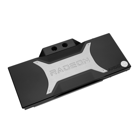
- Page 1 EK-Quantum Vector RX 6800/6900 - AMD Radeon Edition GPU WATER BLOCK USER GUIDE...
- Page 2 Before you start using this product, please follow these basic guidelines: Carefully read the manual before beginning with the installation process. Remove your graphics card from the computer for the safest mounting process to prevent any possible damage to your GPU or its circuit board (PCB).
-
Page 3: Table Of Contents
TABLE OF CONTENTS BOX CONTENTS WATER BLOCK DIMENSIONS TECHNICAL SPECIFICATIONS AND WATER BLOCK PARTS PREPARING THE GRAPHICS CARD REMOVING THE STOCK BACKPLATE REMOVING THE STOCK COOLER CHANGING THE STOCK 2-SLOT I/O BRACKET FOR THE SINGLE-SLOT I/O BRACKET CLEANING THE PCB CUTTING AND PLACING THERMAL PADS APPLYING THERMAL COMPOUND INSTALLING THE WATER BLOCK... -
Page 4: Box Contents
BOX CONTENTS Universal Mounting Mechanism – You may not need every screw from this package. EK-Quantum Vector RX 6800/6900 D-RGB - AMD Radeon Edition M2.5x4 AX1 Screw (30 pcs) PVC Washer M2.5 (28 pcs) M2.5 Nut (1 pc) Allen Key 2 mm (1 pc) Allen Key 2.5 mm (1 pc) -
Page 5: Water Block Dimensions
WATER BLOCK DIMENSIONS 16.50 mm 21.35 mm 119.10 mm 147.10 mm 266.20 mm - 5 -... -
Page 6: Technical Specifications And Water Block Parts
TECHNICAL SPECIFICATIONS AND WATER BLOCK PARTS Technical Specification: - Dimensions (LxHxW): 266 x 133 x 21.5 mm - D-RGB (Addressable RGB) Cable - Length: 500 mm M3 x 6 DIN7991 SCREW M4 x 25 DIN7984 SCREW - D-RGB LED Count: 14 ALU (LED) COVER - D-RGB Connector: Standard 3-Pin (+5V, Data, Blocked, Ground) FC TERMINAL... -
Page 7: Preparing The Graphics Card
PREPARING THE GRAPHICS CARD You will need the following tool: BACKPLATE Phillips Head Screwdriver STEP 1 REMOVING THE STOCK BACKPLATE Use the Phillips head screwdriver to unscrew the twelve (12) marked screws. Evenly untighten four (4) retention bracket screws for easier RETENTION disassembly. -
Page 8: Changing The Stock 2-Slot I/O Bracket For The Single-Slot I/O Bracket
OPTIONAL STEP CHANGING THE STOCK 2-SLOT I/O BRACKET FOR THE SINGLE-SLOT I/O BRACKET In case you prefer it that way, you can change the stock Two-Slot I/O 2-SLOT I/O BRACKET SINGLE SLOT BRACKET Bracket for the Single-Slot Bracket enclosed in this package. For this Step, you will need: M2.5 x 4 AX1 M2.5 Nut... -
Page 9: Cleaning The Pcb
STEP 3 CLEANING THE PCB Wipe off the remains of the original thermal compound using a nonabrasive cloth or Q-tip, as shown in the sample image, until the components and circuit board are completely clean. EK recommends the use of denatured alcohol for removing TIM leftovers. After that, remove all remaining stock thermal pads from the PCB. -
Page 10: Applying Thermal Compound
STEP 2 Thermal Pad F 1.0mm Once cut to size, thermal pads should be placed on the PCB, as illustrated below. EK made sure to provide you with more than an adequate quantity of thermal pads to complete this Step. STEP 2 APPLYING THERMAL COMPOUND STEP 1... -
Page 11: Installing The Water Block
INSTALLING THE WATER BLOCK STEP 1 PLACING THE BLOCK ON THE GRAPHICS CARD This procedure is the same for all full-cover water blocks. Carefully position the water block with preinstalled standoffs on the graphics card. During this process, make sure you have aligned mounting holes of the PCB with holes of the water block (same applies to other tops). -
Page 12: Installing The Backplate
The screws must be present on the places marked below. INSTALLING THE BACKPLATE BACKPLATE DIMENSIONS 266.20 mm - 12 -... -
Page 13: Required Tools
REQUIRED TOOLS Phillips Head Screwdriver Scissors CUTTING AND PLACING THERMAL PADS STEP 1 Your backplate comes with thermal pads that have to be cut into Thermal PAD F 1.5mm (120 x 16 mm) smaller pieces to cover all the VRM components. EK made sure to provide you with more than an adequate quantity of thermal pads to complete this Step. -
Page 14: Attaching The Backplate
STEP 2 Once cut to size, thermal pads should be placed on the backplate, Thermal Pad F 1.5mm as shown on the diagram. Thermal Pad F 2.0 mm STEP 2 ATTACHING THE BACKPLATE Place the backplate on the PCB and make sure all holes are aligned. M2.5 x 8 AX1 Position an M2.5X8 AX1 screw in each of the six (6) mounting holes (as shown in the image) and tighten them evenly with a Phillips... -
Page 15: Checking The Contact In Case Of High Temperatures
CHECKING THE CONTACT IN CASE OF HIGH TEMPERATURES If necessary, temporarily remove the water block to check for uniform surface contact between the block and components. Pay special attention to the VRM section of the graphics card. Check whether the water block makes contact with the intended integrated circuit. Then repeat Steps from the previous section to re-attach the block. -
Page 16: Installation Of Fittings And Tubing
INSTALLATION OF FITTINGS AND TUBING STEP 1 Screw in two (2) G1/4 threaded male fittings. Attach the liquid cooling tubes and connect the water block(s) to the cooling loop. Do not forget to plug the remaining two openings with enclosed EK-Plug G1/4 or its equivalent. EK recommends using EK fittings with all EK water blocks. -
Page 17: Testing The Loop
TESTING THE LOOP To ensure the installation of EK components was successful, we recommend you perform a 24-hour leak test. When your loop is complete and filled with coolant, connect the pump to a PSU outside your system. Do not connect power to any of the other components. -
Page 18: Support And Service
SUPPORT AND SERVICE In case you need assistance, please contact: http://support.ekwb.com/ EKWB d.o.o. Pod lipami 18 1218 Komenda Slovenia - EU SOCIAL MEDIA EKWaterBlocks @EKWaterBlocks ekwaterblocks EKWBofficial ekwaterblocks...
Need help?
Do you have a question about the Vector RX 6800/6900 D-RGB - AMD Radeon Edition and is the answer not in the manual?
Questions and answers