
Related Manuals for Baker Bugbox Ax


Summary of Contents for Baker Bugbox Ax
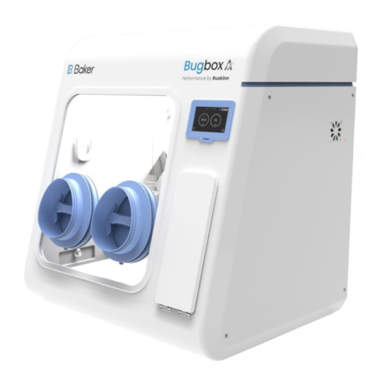
- Page 1 Bugbox Ax Anaerobic Workstation UM-053 Affix Serial Number Sticker Here Bugbox Ax User Manual UM-053 R1.0...
-
Page 2: Product Summary
Product Summary The Baker anaerobic workstations are designed specifically to help microbiologists cope with rising workloads and provide the best primary isolation rates. Features and Benefits Compact size - Your personal workstation • Quick and easy direct access with the gloveless, cuffed Ezee Sleeve system. -
Page 3: Table Of Contents
Precautions ......................8 Symbols........................9 Weight and dimensions ..................10 Transport and storage ....................11 Location and handling of the Bugbox Ax workstation ........11 Environmental Operating Conditions ..............11 Service Requirements ....................12 Electrical Supply Requirements ..............12 Gas Supply Requirements ................13 Workstation overview .................... - Page 4 Offsets ......................25 Data Log ...................... 26 Anaerobic Monitoring (Optional Extra) ............27 O2 Calibration ....................... 29 Micro SD Card .................... 30 Environmental gas composition control ..............31 Environmental control overview ..............31 Using the anoxic indicator strips ..............31 Using the workstation .....................
- Page 5 A heater system maintains the temperature within the workstation between ambient +5°C to 45°C, which is set by the user. Many unique features of the Bugbox Ax workstation are covered in detail in this manual. It is recommended that the user be fully conversant with the instruction and procedures, and that the operator familiarises themselves with all aspects and functions of the system before it is commissions to maintain optimum performance.
-
Page 6: Safety Instructions
All servicing and repairs must be carried out by a qualified customer service engineer. Only • genuine spare parts must be used. In case of damage to the Bugbox Ax disconnect the workstation from the mains outlet and • contact your local distributor. -
Page 7: Regulatory Compliance
Regulatory compliance CE Marking - for sales in the EU & NI This product has been tested and complies with EU Directives 2014/35/EU (Low Voltage), 2014/30/EU (Electromagnetic Compatibility), and 2011/65/EU (RoHS as amended by EU 2015/863) UKCA Marking – for Sales in GB This product also complies with the following Statutory Instruments: SI 2016 No. -
Page 8: North American Region
(EM) radiation and its susceptibility to electromagnetic radiation from other devices. It should be noted that the Bugbox Ax may be affected by high levels of stray EM radiation from other electronic devices (even those which comply with relevant CISPR emission standards) that are being used in close proximity to it. -
Page 9: Symbols
Symbols Before using the Bugbox Ax, please ensure that you are familiar with the symbols. Symbol Meaning Refer to user manual. Alternating current Functional Earth Connection Protective Earth Connection This product complies with the essential EEA requirements for Electrical Safety and Electromagnetic compatibility as set out in the EMC directive 2004/108/EC and the Low Voltage Directive 2006/95/EC Caution, do not remove covers. -
Page 10: Weight And Dimensions
Weight and dimensions The Bugbox Ax workstation weighs approximately 45kg. Figure 1 lists the dimensions of the Bugbox Ax workstation; Figure 1: Bugbox Ax workstation dimensions External width 790 mm External height 872 mm External depth 679 mm Workstation chamber internal width... -
Page 11: Transport And Storage
Transport and storage When not in use, the Bugbox Ax Workstation must only be stored within a temperature of between 0°C and 30°C Storage outside of this range may damage the workstation. Location and handling of the Bugbox Ax workstation The Bugbox Ax should only be installed or relocated by a qualified engineer. -
Page 12: Service Requirements
The mains supply voltage fluctuations must not exceed +/- 10% of the nominal mains voltage. The input voltage and frequency for Bugbox Ax workstations are: Voltage Range... -
Page 13: Gas Supply Requirements
5 bar gauge. A supply pressure greater than this will damage internal components of the Bugbox Ax and will invalidate the warranty. Only the above stated gases are to be used with the workstation. Failure to comply with this may cause the product to become hazardous. -
Page 14: Workstation Overview
The workstation chamber is the main working area of the workstation. Access to the workstation chamber is provided by the glove ports and the interlock. The interlock consists of the interlock chamber, with an inner and an outer door. The Bugbox Ax workstation is controlled via the control panel. -
Page 15: Rear View
Rear view Figure 4 shows the rear view of the Bugbox Ax workstation; Figure 4: Bugbox Ax workstation rear view Page 15 of 55... -
Page 16: Left Side View - Standard Humidifier
Left side view – Standard humidifier Figure 5 shows the left side view of the Bugbox Ax workstation with the standard humidifier; Figure 5: Bugbox Ax workstation left side view Condenser fan Intake – Do not obstruct Condensate tank drain pipe. -
Page 17: Right Side View
Right side view Shows the right side view of the Bugbox Ax workstation; Figure 6: Bugbox Ax workstation right side view Interlock Fan Intake – Do not obstruct Page 17 of 55... -
Page 18: Control System Layout
Control system layout Please familiarise yourself with the control system layout of your Bugbox Ax workstation. Control panel Figure 7 shows the control panel of the Bugbox Ax workstation; Figure 7: Bugbox Ax workstation control panel Temperature Set Point Temperature Reading Low Alarm Icon 4. -
Page 19: Temperature Control
Temperature control The Bugbox Ax workstation can control the workstation chamber temperature between ambient plus 5 C and 45 The temperature in the main chamber can be set using the temperature controller settings on the touchscreen. Setting the temperature; Press the temperature controller dialog on the touchscreen. -
Page 20: Interlock Purge
Interlock Purge The Bugbox Ax workstation has a 9.8 litre interlock that is used for transferring materials and samples into and out of the workstation main chamber. The interlock can be purged of oxygen by pressing the interlock purge button. This pre-conditions the interlock atmosphere to not affect the internal workstation atmosphere. -
Page 21: Humidity Control
Humidity control The Bugbox Ax workstations control the humidity of the workstation chamber from ambient to 85% relative humidity. The humidity level can be increased and decreased by pressing the ‘Min’ & ‘Max’ buttons shown on figure 7. Note: Any equipment installed in the workstation chamber must be suitable for the humidity level inside the workstation chamber. -
Page 22: Settings Menu
Settings Menu The setting menu can be accessed by pressing the ‘Time & Date’ section on the home screen. Figure 9: Settings Menu Commissioning Menu Internal Light On/Off – Press to switch on or off internal light Internal Socket On/Off (Option) - Press to switch the power to the internal socket on or off 4. -
Page 23: Commissioning Menu
Commissioning Menu Figure 10: Commissioning Menu Commission and Gas Control Start / Stop Button – Press to start the 20 minute commission cycle. Once complete the workstation will enter gas control mode and will inject Hydrogen when low pressure is detected. Forced Demand –... -
Page 24: Time & Date Settings
Time & Date Settings Figure 11: Time & Date Menu Increase button – Press to increase the value of the time/date Decrease button – Press to decrease the value of the time/date Page 24 of 55... -
Page 25: Offsets
Offsets Figure 12: Offsets Menu Temperature Sensor Offset – The temperature reading on the main menu can be offset to match a preferred external sensor if required. Press the value and enter the desired offset value. Humidity Sensor Offset – The humidity reading on the main menu can be offset to match a preferred external sensor if required. -
Page 26: Data Log
Data Log Figure 13: Datalog Screen The data log screen is accessed from the Home screen by pressing the Data Log button. The screen displays Date, Time, Temperature and Humidity readings logged every minute. A Micro SD card must be installed for logging to take place. The on screen log displays the values from the last 10 minutes recorded at 1 minute increments. -
Page 27: Anaerobic Monitoring (Optional Extra)
Anaerobic Monitoring (Optional Extra) The Anaerobic Monitoring option displays the current level of Oxygen present within the workstation. The O2 display can be seen in the top left of the screen. The O2 level text changes colour based on the alarm set points that have been set. O2 alarm 2 is indicated by a red text. O2 alarm 1 is indicated by an amber text. - Page 28 To access the alarm set points, press the O2 value. The alarm set points can be changed by pressing the values shown below. Page 28 of 55...
-
Page 29: O2 Calibration
O2 Calibration The O2 sensor fitted with the Anaerobic conditions monitor should be calibrated at least once a month and on installation. To access the calibration menu, press the settings, O2 calibration icon and then press start. When the O2 calibration has passed the time and date will be stored next to last pass result. -
Page 30: Micro Sd Card
Micro SD Card Figure 14: Micro SD Card Slot Micro SD Card Slot – To enable data logging insert the Micro SD card that was supplied with the workstation. To remove the Micro SD card push gently on the it’s edge to release. Note –... -
Page 31: Environmental Gas Composition Control
Using the anoxic indicator strips Anaerobic indicator strips are provided with the Bugbox Ax to verify that the conditions inside the workstation chamber are anaerobic. Additional anaerobic indicator strips can be ordered from your local supplier. See section 9.4.2 for more details. The anaerobic indicator strips should be... -
Page 32: Using The Workstation
Using the workstation Using the interlock The Bugbox Ax workstation has a specially designed interlock for transferring Petri dishes into and out of the workstation chamber. Interlock overview The interlock consists of 2 main components; Interlock outer door • Interlock inner door •... -
Page 33: Transferring Material Into The Workstation Chamber Via The Interlock
Transferring material into the workstation chamber via the interlock To transfer material into the workstation chamber via the interlock; Place the Petri dishes in a large Petri dish holder. • • Open the interlock outer door (see section 8.1.2 for more details). •... -
Page 34: Hand Access To The Main Chamber
Hand access to the main chamber Direct hand access to the workstation chamber is provided via the Ezeeyin glove ports and Ezee-Sleeve The Ezee-Sleeve consists of a gloveless gas tight sleeve and a cuff. • The Ezee-Sleeve attaches to the glove port via two O-rings. Note: The workstation should not be used without the Ezee-Sleeve or EzeeCuff attached. -
Page 35: Vacuum Operation
Vacuum Operation To ensure that no external atmosphere contaminates the workstation, a single vacuum operation is required before Glove Port access. To minimise the time, it is recommended to eliminate as much external atmosphere from the Ezee-Sleeve as possible prior to arm entry. This can be achieved by compressing the Ezee-Sleeve before inserting the hand and arm as shown in Figure Figure 16: Compressed Ezee-Sleeve for Entry •... - Page 36 While the arm is grasping the handle, generate a vacuum by operating the foot pedal for the corresponding glove port. Figure 18: Foot pedals for right and left glove ports The vacuum operation should be continued until the maximum amount of external atmosphere has been removed from the Ezee-Sleeve and the Ezee-Sleeve exerts some pressure on the arm/hand.
-
Page 37: Workstation Entry
Workstation Entry Once the vacuum has been achieved, the Glove Port Handle can now be rotated in either direction to unlock the Glove Port Cap. As there is a strong vacuum within the Ezee-Sleeve, removal of the Cap can require a reasonable amount of force. - Page 38 Figure 22: Glove port cap storage location inside workstation Repeat the procedure for the other hand (if both hands are entering the workstation chamber). Page 38 of 55...
-
Page 39: Workstation Exit
Workstation Exit Remove Cap from storage brackets, and ensure the handle is oriented in a vertical position on the Cap. The Handle is designed with “indexing” detent features to help locate the Handle relative to the Cap. Drawing the handle into the Glove Port, replace the cap, using the location posts and graphic to orient the Cap correctly on the Glove Port. -
Page 40: Rear Shelf
Rear shelf The Bugbox Ax workstation has a rear shelf for additional storage within the workstation chamber. The weight limit for the shelf is 5.5kg. The weight on the shelf must be evenly distributed. Optional extras Your Bugbox Ax workstation may be fitted with optional extra parts to provide added functionality. -
Page 41: Single Plate Entry System (Spes)
Single Plate Entry System (SPES) A SPES is provided for quick and easy direct access to the workstation chamber, for loading materials. The SPES is also known as the mailbox. To open the SPES turn the knob half a turn anti clockwise until the knob stops and lower the plate Load plate through the opening. -
Page 42: Internal Power Socket
Internal power socket An internal power socket is provided within the workstation chamber. The socket is located on the left hand side, underneath the rear shelf. The maximum permissible power rating of equipment connected to the internal socket is shown in Figure 25. -
Page 43: Gas Sample Port
Figure 27: Universal Cable Gland Gas sample port The gas sample port can be used to collect a gas sample from the workstation chamber. To use the gas sample port; Remove the outer cap. • Push a needle connected to a syringe through the internal sponge of the gas sample port. •... - Page 44 When the vacuum is no longer required, remove the internal vacuum hose from the • vacuum port by pressing the top of the metal part of the internal section of the vacuum port and pulling the vacuum hose. The hose should release from the vacuum port, sealing the vacuum port.
-
Page 45: Cleaning And Maintenance
Cleaning and maintenance Cleaning the workstation To ensure that the Bugbox Ax workstation remains at optimum working conditions, it must be cleaned on a regular basis. A basic clean is required after each use. Deep cleaning is required at regular intervals, dependent upon the nature of the materials used in the workstation. As a guide, a deep clean should be performed at between 3-6 month intervals. -
Page 46: Cleaning Procedure - Deep Clean
Cleaning procedure – deep clean To deep clean the workstation; Preparing the workstation Remove all cells/ samples to an alternative storage facility. • • Switch the workstation off at the mains and remove the plug from the mains. Remove the Ezee Sleeves •... -
Page 47: Maintaining The Workstation - End User Maintenance
Many basic tasks can be performed by the end user. Replacing the detox and catalyst sachets A detox and a catalyst sachet are supplied with the Bugbox Ax workstation. The detox sachet adsorbs volatile organic compounds, improving the air quality within the workstation chamber. -
Page 48: Replacing The Mains Plug Fuse - Uk Users Only
Close the glove ports using the glove port covers. • Reinstall the Ezee Sleeves. • Reconnect the Bugbox Ax to the mains power supply and switch the Bugbox Ax on. • • Allow the Bugbox Ax to reach an anaerobic environment in the workstation chamber by leaving the Bugbox Ax for a period of approximately 1 hour. -
Page 49: Replacing The Mains Fuses
Replacing the mains fuses To replace the mains fuses; • Switch off the Bugbox Ax. Remove the plug from the mains socket. • • Remove the mains fuse drawer by using a small flat bladed screwdriver. Depress and rotate anti clockwise to release. Error! Reference source not found. -
Page 50: Service Requirements
Service requirements To maintain the best performance from your Bugbox Ax workstation, it must be serviced at regular intervals. Figure 32 lists the servicing requirements, intervals and persons capable of performing the service; Figure 32: Bugbox Ax servicing requirements Action... -
Page 51: Spare Parts And Cleaning Agents
Spare parts and cleaning agents Figure 33 lists the spare parts and cleaning agents available for your Bugbox Ax workstation. To order spare parts, please contact your local distributor for the latest pricing and availability. All items are sold individually except where stated. -
Page 52: Workstation Malfunction
Workstation malfunction In the event of a workstation malfunction, please check section 9.6 for a list of common problems and solutions. If you cannot find a solution to your problem, please contact your local distributor, quoting the serial number of your workstation. Common problems and solutions Workstation general problems Please consult the list shown below as a reference in the event of a malfunction of your workstation. -
Page 53: Gas Consumption/ Environmental Control Problems
Gas consumption/ environmental control problems Bugbox Ax is fitted with a gas demand indicator (item 7 in Figure 7). The indicator illuminates when gas is injected into the workstation chamber. When the workstation is at rest, the gas demand indicator should illuminate once every 20 minutes. At rest is defined as the workstation chamber is in an anaerobic condition with no access to the interlock chamber, i.e. -
Page 54: Warranty Information
Bugbox Ax otherwise than in the normal course of a business. THIS WARRANTY DOES NOT APPLY IN THE FOLLOWING CIRCUMSTANCES: (A) IF THE Ruskinn Technology Limited Bugbox Ax HAS BEEN REPAIRED BY PERSONS NOT AUTHORIZED BY Ruskinn Technology Limited; OR (B) THE Ruskinn Technology Limited Bugbox Ax and associated accessories/peripherals HAVE BEEN ALTERED, MODIFIED, OR MISUSED;... -
Page 55: Contact Details
Ruskinn Technology Limited is a registered company in United Kingdom, company number 05692599 Ruskinn Technology Limited is VAT registered in United Kingdom, VAT number 870194126 Ruskinn Technology Limited is a wholly owned subsidiary of the Baker Company Page 55 of 55...
Need help?
Do you have a question about the Bugbox Ax and is the answer not in the manual?
Questions and answers