Table of Contents
Advertisement
P. O. Drawer E / 161 Gatehouse Road / Sanford, Maine 04073 / USA
800-992-2537 / 207-324-8773 / Fax: 207-324-3869 / bakerco@bakerco.com /
bakerco.com
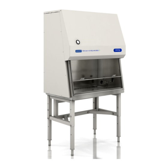
SERVICE MANUAL
Class II, Type A2
Biological Safety Cabinet
MODELS:
SG404 / SG504 / SG604
SG404-INT / SG504-INT / SG604-INT
SG404-JPN / SG504-JPN / SG604-JPN
SG404-AUS / SG604-AUS
M-models are UL listed but not NSF listed
This manual includes information for proper service of this cabinet.
We recommend that it be kept near the cabinet for ready reference.
389D001 Rev G
Advertisement
Table of Contents


Need help?
Do you have a question about the SterilGARD SG404 and is the answer not in the manual?
Questions and answers