Advertisement
Revision
A
B
C
398D003 Rev B
INSTALLATION MANUAL
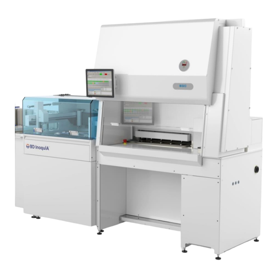
Biological Containment Cabinet
BD InoqulA
Date
06/26/14
Initial release
07/28/14
Revised and updated instructions
08/18/14
Revised and updated instructions page 4
P. O. Drawer E / 161 Gatehouse Road / Sanford, Maine 04073 / USA
800-992-2537 / 207-324-8773 / Fax: 207-324-3869 / bakerco@bakerco.com
MODEL
BDINQ400
Description
i
Advertisement

Related Manuals for Baker BD InoqulA


Summary of Contents for Baker BD InoqulA
- Page 1 P. O. Drawer E / 161 Gatehouse Road / Sanford, Maine 04073 / USA 800-992-2537 / 207-324-8773 / Fax: 207-324-3869 / bakerco@bakerco.com INSTALLATION MANUAL Biological Containment Cabinet BD InoqulA MODEL BDINQ400 Revision Date Description 06/26/14 Initial release 07/28/14 Revised and updated instructions...
-
Page 2: Table Of Contents
P. O. Drawer E / 161 Gatehouse Road / Sanford, Maine 04073 / USA 800-992-2537 / 207-324-8773 / Fax: 207-324-3869 / bakerco@bakerco.com TABLE OF CONTENTS I – TOOL & HARDWARE LIST BDINQ400 CABINET INSTALLATION ..........1 II – PREPARING THE SA MODULE & CABINET FOR INSTALLATION .........2 III –... -
Page 3: I - Tool & Hardware List Bdinq400 Cabinet Installation
I – TOOL & HARDWARE LIST BDINQ400 CABINET INSTALLATION Tools Required Hardware - fasteners • ”, ”, ” bits Required) • SAE Hex Drive Bits ( #8-32 SS Hex Cap Nut #10553 • ” Drive • Cordless Drill- #8-32 SS Locking Hex Cap Nut #10559 •... -
Page 4: Preparing The Sa Module & Cabinet For Installation
II – PREPARING THE SA MODULE & CABINET FOR INSTALLATION Step 1: Remove the right side duct cover and lower SA module panels to gain access to the mounting holes for the BDINQ400 cabinet on the SA chassis underneath the table top. Remove front grille. - Page 5 Step 3: Using templates 398F402 and 398F403 provided and shipped with the cabinet, apply gasket to the table top around the perimeter of the templates as indicated by dashed red lines for sealing between the bottom of the cabinet and the table top. Align with holes in table top Template orientation...
- Page 6 Step 5: Using a 5/32" Allen wrench tool, remove the outer right side panel of the cabinet and then remove the inner access panel by removing the 1/4” hex head screws. Outer side panel Inner access panel Step 6: Unscrew shipping screws attached to the viewscreen weight box and raise viewscreen. Step 6: Attach front support bracket to the left and right view screen guide mounting holes prior to lifting ”[1425 mm] Support bracket...
-
Page 7: Lifting And Placement Of The Bdinq400
Ensure that all four lifting hoist rings are properly attached to the top of the cabinet. Hoist rings [Baker p/n 43674] Step 2: The cabinet’s net weight is 390 lbs [177 kg] with the center of gravity located to the right of center. -
Page 8: Manual Lifting Of The Bdinq400
IV – MANUAL LIFTING OF THE BDINQ400 REDUCING THE LIFTING WEIGHT OF THE CABINET Step 1: Supporting the supply diffuser with one hand, remove the securing hardware with an 11/32 ratchet wrench or nut driver. Using two hands lower the front edge of the diffuser down. Then while holding the edge firmly, carefully pull it forward off its rear mounting studs and remove it from the cabinet work area. - Page 9 Step 4: Open the fascia panel by firmly grabbing the lower edge of the fascia and carefully pivot it to the full open position. While supporting the fascia open with one hand use the other hand to pivot two fascia support arms on either side of the fascia away from the cabinet. Lower the fascia panel onto the supports.
- Page 10 Step 7: Close the viewscreen and remove the left and right viewscreen guide brackets. 1/4-20 screws Step 8: Loosen the four 5/16” hex nuts, (2 each side) that secure the electrical board. Do not completely remove these. Cut the wire ties securing cabinet wiring to the left and right of the cabinet front seal panel Step 9: Temporarily secure the electrical board to the wire tie cut-outs located using ty-raps Wire tie cut-out...
- Page 11 Step 10: Remove view screen cable screw on each side of the viewscreen, slightly lift up the viewscreen and move sideways to clear cable bracket Step 11: Lower control board and hang the top of the board off the lower screws. This position will allow full access to the front seal panel hardware.
- Page 12 Step 13: Use a 5/32" Allen wrench tool to remove all ten front seal panel bolts and seal washers from the front seal panel. Step 14: Pull the front seal panel off from the cabinet. This may require prying up on a corner of the panel to release hold.
- Page 13 ATTACHING THE LIFTING AIDS TO THE CABINET Step 1: Attach the lifting aid brackets to each side of the cabinet by inserting the existing side panel screws 1/4-20 hex head panel screws 1/4-20 hexhead panel screws Step 2: Attach the lifting bars to the brackets using 1/4-20 hex head screws Step 3: For ergonomic reason lift the cabinet onto a lift table that can be raised to the InoqulA table top height.
-
Page 14: Attachment Of The Bdinq400
V – ATTACHMENT OF THE BDINQ400 Step 1: Insert (2) M6 x 30 mounting screws on left side of the cabinet from underneath the SA chassis table top. Mounting locations Table top Step 2: Insert three (3) M6 x 30 mounting screws in the slots located in right side plenum. Mounting locations Step 3: Attach all M6 mounting hardware for cabinet rear wall to shifter module. - Page 15 Step 5: Remove the towel guard and remove power cord plug and M12 male signal connector. Feed all cables from bottom of cabinet through the bottom plenum into the designated cable glands. Afterwards re-attach M12 male signal connector and power cord plug. Connect touch screen cables to appropriate locations on the rear of the InoqulA PC.
Need help?
Do you have a question about the BD InoqulA and is the answer not in the manual?
Questions and answers